CN201708330U - Electric connector - Google Patents
Electric connector Download PDFInfo
- Publication number
- CN201708330U CN201708330U CN2010201719495U CN201020171949U CN201708330U CN 201708330 U CN201708330 U CN 201708330U CN 2010201719495 U CN2010201719495 U CN 2010201719495U CN 201020171949 U CN201020171949 U CN 201020171949U CN 201708330 U CN201708330 U CN 201708330U
- Authority
- CN
- China
- Prior art keywords
- receiving space
- electric connector
- contact site
- afterbody
- groove
- Prior art date
- Legal status (The legal status is an assumption and is not a legal conclusion. Google has not performed a legal analysis and makes no representation as to the accuracy of the status listed.)
- Expired - Fee Related
Links
Images


Classifications
-
- H—ELECTRICITY
- H01—ELECTRIC ELEMENTS
- H01R—ELECTRICALLY-CONDUCTIVE CONNECTIONS; STRUCTURAL ASSOCIATIONS OF A PLURALITY OF MUTUALLY-INSULATED ELECTRICAL CONNECTING ELEMENTS; COUPLING DEVICES; CURRENT COLLECTORS
- H01R13/00—Details of coupling devices of the kinds covered by groups H01R12/70 or H01R24/00 - H01R33/00
- H01R13/02—Contact members
- H01R13/22—Contacts for co-operating by abutting
- H01R13/24—Contacts for co-operating by abutting resilient; resiliently-mounted
- H01R13/2407—Contacts for co-operating by abutting resilient; resiliently-mounted characterized by the resilient means
-
- H—ELECTRICITY
- H01—ELECTRIC ELEMENTS
- H01R—ELECTRICALLY-CONDUCTIVE CONNECTIONS; STRUCTURAL ASSOCIATIONS OF A PLURALITY OF MUTUALLY-INSULATED ELECTRICAL CONNECTING ELEMENTS; COUPLING DEVICES; CURRENT COLLECTORS
- H01R12/00—Structural associations of a plurality of mutually-insulated electrical connecting elements, specially adapted for printed circuits, e.g. printed circuit boards [PCB], flat or ribbon cables, or like generally planar structures, e.g. terminal strips, terminal blocks; Coupling devices specially adapted for printed circuits, flat or ribbon cables, or like generally planar structures; Terminals specially adapted for contact with, or insertion into, printed circuits, flat or ribbon cables, or like generally planar structures
- H01R12/70—Coupling devices
- H01R12/71—Coupling devices for rigid printing circuits or like structures
- H01R12/72—Coupling devices for rigid printing circuits or like structures coupling with the edge of the rigid printed circuits or like structures
- H01R12/722—Coupling devices for rigid printing circuits or like structures coupling with the edge of the rigid printed circuits or like structures coupling devices mounted on the edge of the printed circuits
- H01R12/727—Coupling devices presenting arrays of contacts
Landscapes
- Coupling Device And Connection With Printed Circuit (AREA)
Abstract
本实用新型公开了一种电连接器,用以电性连接第一电器元件及第二电器元件,该电连接器包括绝缘本体(110)及组装于绝缘本体的导电端子,绝缘本体包括基部、自基部一侧延伸的舌板及形成在基部另一侧的收容空间,导电端子包括位于舌板的用以连接第一电器元件的接触部(122)及用以连接第二电器元件的尾部(132),尾部至少部分倾斜延伸入收容空间而具有弹性。本电连接器适用转接作用,且该端子适用接触电路板及对接连接器。
The utility model discloses an electrical connector, which is used to electrically connect a first electrical component and a second electrical component. The electrical connector includes an insulating body (110) and a conductive terminal assembled in the insulating body. The insulating body includes a base, a The tongue plate extending from one side of the base and the receiving space formed on the other side of the base, the conductive terminal includes a contact portion (122) on the tongue plate for connecting the first electrical component and a tail portion (122) for connecting the second electrical component ( 132), at least part of the tail extends obliquely into the receiving space and has elasticity. The electrical connector is suitable for transfer function, and the terminal is suitable for contacting circuit boards and docking connectors.
Description
【技术领域】【Technical field】
本实用新型涉及一种电连接器,尤其是一种适用于转接作用的电连接器。The utility model relates to an electric connector, in particular to an electric connector suitable for switching function.
【背景技术】【Background technique】
美国专利公告第6767235号公开了一种固定于电路板的电连接器,其包括绝缘本体及导电端子,导电端子的尾部朝后延伸,且绝缘本体基部两端朝后延伸一对夹持部,电路板一端夹持于该夹持部中,各导电端子尾部抵压于电路板上相应的导电片上,这种夹持电路板的结构,不利于产品结构小型化,且浪费材料。U.S. Patent No. 6767235 discloses an electrical connector fixed on a circuit board, which includes an insulating body and a conductive terminal. The tail of the conductive terminal extends backward, and a pair of clamping parts extend backward from both ends of the base of the insulating body. One end of the circuit board is clamped in the clamping part, and the tails of the conductive terminals are pressed against the corresponding conductive sheets on the circuit board. This structure of clamping the circuit board is not conducive to the miniaturization of the product structure and wastes materials.
【实用新型内容】【Content of utility model】
本实用新型所要解决的技术方案是提供一种电连接器,其有利于减小产品体积。The technical solution to be solved by the utility model is to provide an electric connector, which is beneficial to reduce the volume of the product.
本实用新型的目的是通过以下技术方案实现的:一种电连接器,用以电性连接第一电器元件及第二电器元件,该电连接器包括绝缘本体及组装于绝缘本体的导电端子,绝缘本体包括基部、自基部一侧延伸的舌板及形成在基部另一侧的收容空间,导电端子包括位于舌板的用以连接第一电器元件的接触部及用以连接第二电器元件的尾部,尾部至少部分倾斜延伸入收容空间而具有弹性。The purpose of this utility model is achieved through the following technical solutions: an electrical connector for electrically connecting the first electrical component and the second electrical component, the electrical connector includes an insulating body and a conductive terminal assembled in the insulating body, The insulating body includes a base, a tongue plate extending from one side of the base, and a receiving space formed on the other side of the base. The conductive terminal includes a contact portion on the tongue plate for connecting the first electrical component and a contact portion for connecting the second electrical component. The tail part is at least partly obliquely extended into the accommodation space and has elasticity.
相较于现有技术,本实用新型的跟对接部相对的收容空间可收容第二电器元件,可有效地减小电连接器的体积,节省了材料。Compared with the prior art, the accommodating space opposite to the docking part of the utility model can accommodate the second electrical component, which can effectively reduce the volume of the electrical connector and save materials.
【附图说明】【Description of drawings】
图1是本实用新型第一实施例的电连接器安装于电路板的立体图。FIG. 1 is a perspective view of an electrical connector installed on a circuit board according to a first embodiment of the present invention.
图2是图1电连接器安装于电路板另一视角的立体图。FIG. 2 is a perspective view from another perspective of the electrical connector of FIG. 1 installed on the circuit board.
图3是图1电连接器与电路板的立体分解图。FIG. 3 is an exploded perspective view of the electrical connector and the circuit board in FIG. 1 .
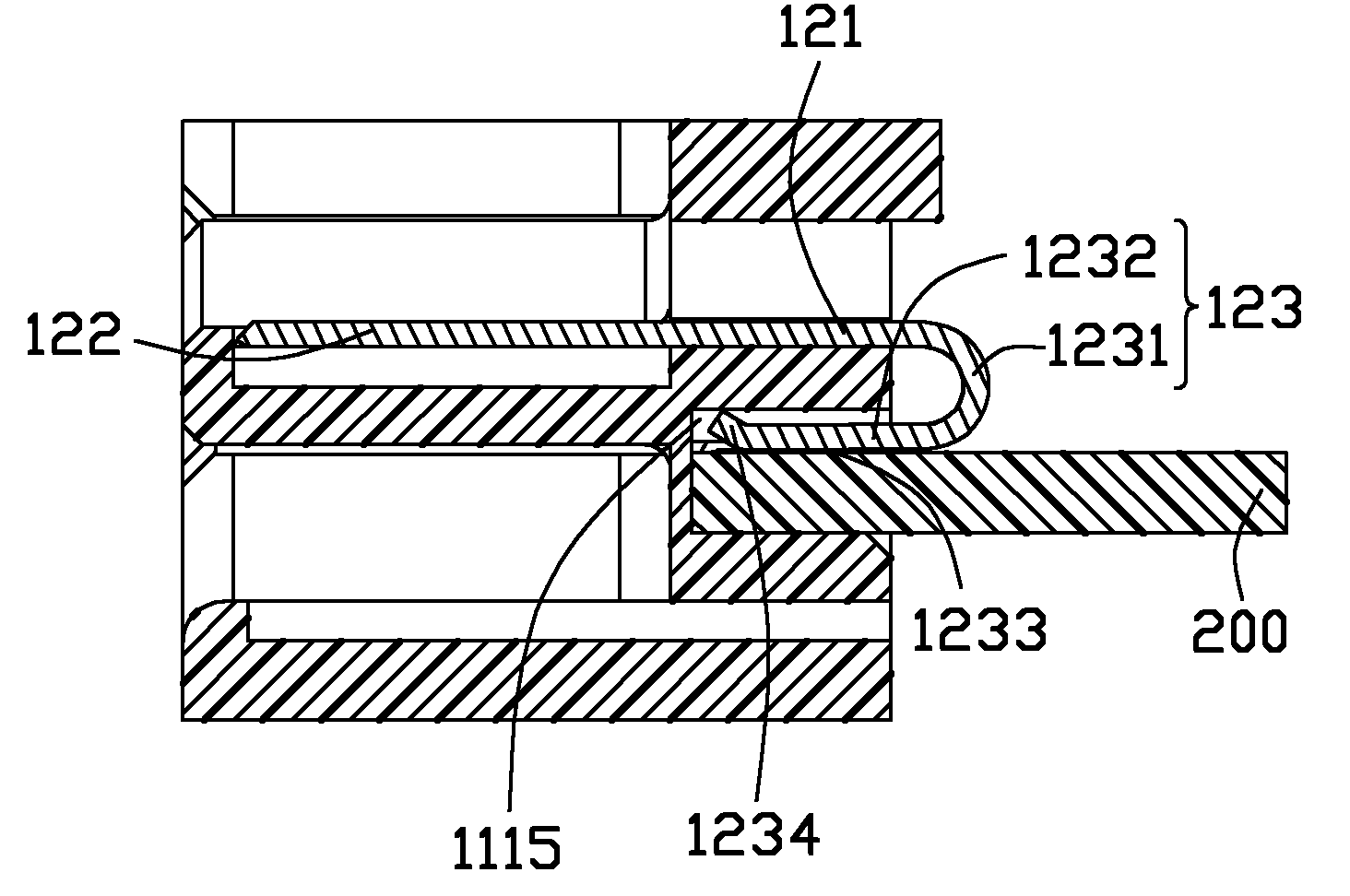
图4是沿图1的A-A线剖视图,以清楚显示端子跟电路板的配合关系。FIG. 4 is a cross-sectional view along line A-A of FIG. 1 to clearly show the matching relationship between the terminal and the circuit board.
图5是本实用新型第二实施例的电连接器的立体图。FIG. 5 is a perspective view of the electrical connector of the second embodiment of the present invention.
图6是图5电连接器另一视角的立体图。FIG. 6 is a perspective view of another viewing angle of the electrical connector of FIG. 5 .
图7是图5电连接器局部的立体分解图。FIG. 7 is an exploded perspective view of a part of the electrical connector in FIG. 5 .
【具体实施方式】【Detailed ways】
图1至图4显示了本实用新型的第一实施例,第一实施例的电连接器100的一端口对接于一对接电连接器(未图示),另一端口则连接一电路板200。图5至图7显示了本实用新型的第二实施例,第二实施例的电连接器300的一端口对接于一对接电连接器(未图示),另一端口则连接另一对接连接器(未图示)。Fig. 1 to Fig. 4 have shown the first embodiment of the utility model, and one port of the
请参阅图1至图3,本实用新型电连接器组件1包括电连接器100及电路板200,电连接器100包括绝缘本体110及组装于绝缘本体110的若干个导电端子120。Referring to FIGS. 1 to 3 , the electrical connector assembly 1 of the present invention includes an
绝缘本体110包括基部111及对接部112,对接部112两侧设有一对的导向部113,且该导向部113自基部111前端面1111向前延伸而形成槽状结构。基部111呈纵长状,且具有相对的前端面1111及后端面1112,对接部112包括一对大小不一、呈L型的舌板1120,这对舌板1120自前端面1111延伸而成且均具有接触面1121,请特别参阅图3,基部111的后端面1112朝向前端面1111方向凹设有一对与舌板1120相对应的收容空间1113,这对收容空间1113之间由一间隔壁1119隔开。The
请结合参阅图3及图4,导电端子120具有固持于基部111的固持部121、自固持部121前端向前延伸形成的呈板状的接触部122及自固持部121后端延伸形成的尾部123,接触部122暴露于各舌板1120的接触面1121以与对接端子(图未示)相接触,导电端子120尾部123包括突出于后端面1112的弯曲部1231及自弯曲部1231末端朝基部111前端面1111方向延伸形成的焊接部1232,该弯曲部1231呈U型或C型,焊接部1232倾斜向下延伸入收容空间1113。收容空间1113包括自其顶面1116向上凹设形成的若干个凹槽1115及位于收容空间上方的端子槽1117,该端子槽跟对接部112的槽道对齐,以供端子的尾部穿过,各导电端子120焊接部1232在电路板插入时,焊接部1232被向上挤压而至少部分收容在凹槽内(图4清楚可见),各焊接部1232的焊接焊接面1233则突出于收容空间的顶面1116,凹槽1115的设置可以起到定位及预留焊接部1232移动的作用。当然,也可以利用弹性抵压实现电路板跟端子的尾部的接触,对应标号1232所指部分则可定义为弹性部。弹性部的末端1234向凹槽方向弯折,在弹性部被挤压时其抵靠在凹槽的内壁面上,有助于增强弹性部的弹性。弯曲部1231突伸出后端面则可部分抵压在电路板上,有助于稳定电路板。3 and 4, the
请参阅图3,电路板200一端包括一对夹持于收容空间1113的夹持部210,各夹持部210上设有与各导电端子120的焊接部1232相对应的导电垫片211。Referring to FIG. 3 , one end of the
请参阅图4,当电路板200的夹持部210插设于绝缘本体110的收容空间1113内时,各导电端子120的焊接部/弹性抵压部1232抵压于电路板200,且各焊接部1232的焊接面1233与夹持部210表面的导电垫片211相接触,从而实现电连接。通过端子固定电路板200,可以有效地减小电连接器100的体积,节省材料。另外,收容空间1113的底面进一步设有凸肋1118(参图3),该凸肋1118与电路板200底面相配合以更好地夹持电路板200。接触部122跟对接连接器接触的面朝上,收容空间内的尾部123跟电路板接触的面朝下,两个接触的面朝向相反的方向。Please refer to FIG. 4, when the
请参阅图5至图7,电连接器300的结构类似于第一实施例的电连接器100,电连接器的绝缘本体3的基部31的一侧设有对接部32,该对接部由两呈倒L型的平列舌板构成,舌板的一侧面平列设有若干端子4,基部31的另一侧设有收容空间33,该收容空间呈倒L型,该收容空间可对接一另一电连接器(比如线缆连接器),该另一电连接器的插头类似于本电连接器的对接部32,从而实现本电连接器的转接作用。该收容空间33的底壁34设有若干凹槽341,该等凹槽上下贯穿及向后贯穿。对接部31的收容端子的收容槽向后贯穿基部31。5 to 7, the structure of the
导电端子4包括固持于基部的固持部41及自固定部两端分别延伸的接触部42及尾部43,接触部42呈板状而埋设于舌板的一侧面,尾部43自收容空间33底壁34的外侧面弯折而倾斜延伸入收容空间33而形成弹性部431。当另一电连接器插入收容空间,弹性部341则被向下挤压而收容在凹槽341内。因本电连接器用以于另一对接电连接器对接,故尾部的连接弹性部的弯曲部432收容在凹槽的开口处,而未突伸出绝缘本体的后端面。The
本实用新型提供了用于转接的电连接器100,300,该电连接器相对对接部设有收容空间1113,33,用以收容另一对接连接器或者电路板。为方便描述,定义跟对接部112,32对接的对接连接器为第一电器元件,跟收容空间配合的另一对接连接器或者电路板为第二电器元件,焊接部(抵压弹性部)1233或弹性部431均用以跟第二电器元件配合,故统称为第二接触部。The utility model provides
Claims (10)
Priority Applications (2)
| Application Number | Priority Date | Filing Date | Title |
|---|---|---|---|
| CN2010201719495U CN201708330U (en) | 2009-10-29 | 2010-04-27 | Electric connector |
| US12/874,376 US8162680B2 (en) | 2009-10-29 | 2010-09-02 | Board-mounted electrical connector |
Applications Claiming Priority (3)
| Application Number | Priority Date | Filing Date | Title |
|---|---|---|---|
| CN200910309007.0 | 2009-10-29 | ||
| CN200910309007 | 2009-10-29 | ||
| CN2010201719495U CN201708330U (en) | 2009-10-29 | 2010-04-27 | Electric connector |
Publications (1)
| Publication Number | Publication Date |
|---|---|
| CN201708330U true CN201708330U (en) | 2011-01-12 |
Family
ID=43445482
Family Applications (1)
| Application Number | Title | Priority Date | Filing Date |
|---|---|---|---|
| CN2010201719495U Expired - Fee Related CN201708330U (en) | 2009-10-29 | 2010-04-27 | Electric connector |
Country Status (2)
| Country | Link |
|---|---|
| US (1) | US8162680B2 (en) |
| CN (1) | CN201708330U (en) |
Cited By (1)
| Publication number | Priority date | Publication date | Assignee | Title |
|---|---|---|---|---|
| CN107768870A (en) * | 2017-10-16 | 2018-03-06 | 番禺得意精密电子工业有限公司 | Electric connector |
Families Citing this family (6)
| Publication number | Priority date | Publication date | Assignee | Title |
|---|---|---|---|---|
| TWM397639U (en) * | 2010-07-05 | 2011-02-01 | Nai-Chien Chang | Multiple-interface Connector |
| TWM436982U (en) * | 2011-10-28 | 2012-09-01 | Aces Electronic Co Ltd | Power connector |
| US8956194B2 (en) * | 2013-05-07 | 2015-02-17 | Cheng Uei Precision Industry Co., Ltd. | Battery connector and electrical terminal thereof |
| US9728876B1 (en) * | 2016-11-04 | 2017-08-08 | Cen Link Co., Ltd. | Electric connector |
| CN110100354A (en) * | 2016-12-22 | 2019-08-06 | 3M创新有限公司 | Connectors using printed circuit boards |
| US11757223B2 (en) * | 2021-04-14 | 2023-09-12 | Dell Products L.P. | Receptacle connector socket with embedded bus bar |
Family Cites Families (5)
| Publication number | Priority date | Publication date | Assignee | Title |
|---|---|---|---|---|
| DE60208885T2 (en) * | 2002-01-30 | 2006-08-31 | Fujitsu Component Ltd. | INTERCONNECTS |
| US6767235B2 (en) * | 2002-07-26 | 2004-07-27 | Hon Hai Precision Ind. Co., Ltd. | Electrical connector having retention system for mounting onto a printed circuit board |
| US6699049B1 (en) * | 2003-03-26 | 2004-03-02 | Hon Hai Precision Ind. Co., Ltd. | Electrical connector with enhanced housing structure |
| JP4212955B2 (en) * | 2003-05-27 | 2009-01-21 | 富士通コンポーネント株式会社 | Plug connector for balanced transmission |
| US20070015385A1 (en) * | 2005-07-15 | 2007-01-18 | Johnson Yang | Connector with double row terminals |
-
2010
- 2010-04-27 CN CN2010201719495U patent/CN201708330U/en not_active Expired - Fee Related
- 2010-09-02 US US12/874,376 patent/US8162680B2/en not_active Expired - Fee Related
Cited By (2)
| Publication number | Priority date | Publication date | Assignee | Title |
|---|---|---|---|---|
| CN107768870A (en) * | 2017-10-16 | 2018-03-06 | 番禺得意精密电子工业有限公司 | Electric connector |
| CN107768870B (en) * | 2017-10-16 | 2020-06-09 | 番禺得意精密电子工业有限公司 | Electrical connector |
Also Published As
| Publication number | Publication date |
|---|---|
| US20110104909A1 (en) | 2011-05-05 |
| US8162680B2 (en) | 2012-04-24 |
Similar Documents
| Publication | Publication Date | Title |
|---|---|---|
| CN201204309Y (en) | electrical connector | |
| CN201355730Y (en) | electrical connector | |
| CN201142390Y (en) | electrical connector | |
| CN201708330U (en) | Electric connector | |
| CN202196951U (en) | Plate terminal connector | |
| CN204696369U (en) | Electric connector | |
| CN201515054U (en) | Board terminal electric connector | |
| CN201336452Y (en) | Electric connector | |
| CN201112786Y (en) | Electrical connectors and their components | |
| CN201075507Y (en) | Electric Connector | |
| CN200941505Y (en) | electrical connector | |
| US8123541B2 (en) | Electrical connector with expanded cover | |
| CN201207474Y (en) | battery connector | |
| CN201160138Y (en) | Electrical Connector Assembly | |
| CN209929539U (en) | Stable supporting type female terminal and male-female plug-in electric connector applied by same | |
| CN201594605U (en) | battery connector | |
| CN201194271Y (en) | Socket connector, plug connector and socket and plug connector combination | |
| CN201285841Y (en) | Electric connector | |
| CN201829671U (en) | Electric connector | |
| CN2800568Y (en) | Electric connector module | |
| CN201112692Y (en) | electrical connector | |
| CN203481542U (en) | Electric connector | |
| CN216698927U (en) | Terminal pin, conductive terminal and electric connector | |
| CN201667429U (en) | Electric connector | |
| CN201667422U (en) | Electric connector |
Legal Events
| Date | Code | Title | Description |
|---|---|---|---|
| C14 | Grant of patent or utility model | ||
| GR01 | Patent grant | ||
| CF01 | Termination of patent right due to non-payment of annual fee | ||
| CF01 | Termination of patent right due to non-payment of annual fee |
Granted publication date: 20110112 Termination date: 20190427 |