CN201119537Y - Portable drinking water bottle cap - Google Patents
Portable drinking water bottle cap Download PDFInfo
- Publication number
- CN201119537Y CN201119537Y CNU2007200573530U CN200720057353U CN201119537Y CN 201119537 Y CN201119537 Y CN 201119537Y CN U2007200573530 U CNU2007200573530 U CN U2007200573530U CN 200720057353 U CN200720057353 U CN 200720057353U CN 201119537 Y CN201119537 Y CN 201119537Y
- Authority
- CN
- China
- Prior art keywords
- water
- established
- cover plate
- bottle cap
- suction pipe
- Prior art date
- Legal status (The legal status is an assumption and is not a legal conclusion. Google has not performed a legal analysis and makes no representation as to the accuracy of the status listed.)
- Expired - Fee Related
Links
- 235000020188 drinking water Nutrition 0.000 title claims abstract description 15
- 239000003651 drinking water Substances 0.000 title claims abstract description 15
- XLYOFNOQVPJJNP-UHFFFAOYSA-N water Substances O XLYOFNOQVPJJNP-UHFFFAOYSA-N 0.000 claims abstract description 79
- 238000001746 injection moulding Methods 0.000 claims abstract description 3
- 230000001105 regulatory effect Effects 0.000 claims description 2
- 239000003292 glue Substances 0.000 claims 2
- 238000012946 outsourcing Methods 0.000 claims 1
- 239000007787 solid Substances 0.000 claims 1
- 230000035622 drinking Effects 0.000 abstract description 3
- 230000000149 penetrating effect Effects 0.000 abstract 1
- 239000010902 straw Substances 0.000 description 15
- 230000001012 protector Effects 0.000 description 5
- 239000011324 bead Substances 0.000 description 3
- 238000002347 injection Methods 0.000 description 2
- 239000007924 injection Substances 0.000 description 2
- 239000000243 solution Substances 0.000 description 2
- 238000010521 absorption reaction Methods 0.000 description 1
- 230000009286 beneficial effect Effects 0.000 description 1
- 235000013361 beverage Nutrition 0.000 description 1
- 230000000694 effects Effects 0.000 description 1
- 238000003780 insertion Methods 0.000 description 1
- 230000037431 insertion Effects 0.000 description 1
- 238000000034 method Methods 0.000 description 1
Images


Landscapes
- Closures For Containers (AREA)
Abstract
Description
技术领域 technical field
本实用新型涉及一种饮水用具,尤其是饮用水瓶盖体及吸管。The utility model relates to a drinking water utensil, in particular to a drinking water bottle cap and a straw.
背景技术 Background technique
目前,人们在户外活动中,常用各种瓶体来盛装饮用水或饮料。饮用时,通常是用嘴对准瓶口直接饮用。但是,在某些运动过程中,采用上述方式饮水会感到不方便,甚至不能采用上述方式饮水。为解决上述问题,可采用一条较长的吸水管插入瓶中,通过吸水管来吸食瓶内的水。插入吸水管后,若瓶盖上没有进气空隙,吸水时,瓶内会产生负压,水较难吸出,因此,现有的该类瓶盖上都设有进气空隙。该类瓶盖在非吸食状态下,若瓶体晃动或翻倒,瓶内的水会经其进气空隙渗出。At present, people use various bottles to hold drinking water or beverages in outdoor activities. When drinking, usually aim at the mouth of the bottle and drink directly with your mouth. However, during some exercise, it is inconvenient to drink water in the above-mentioned way, or even impossible to drink in the above-mentioned way. For addressing the above problem, a longer water suction pipe can be adopted to insert in the bottle, and the water in the bottle is sucked by the water suction pipe. After inserting the water suction pipe, if there is no air intake space on the bottle cap, negative pressure will be generated in the bottle when water is absorbed, and the water is difficult to suck out. Therefore, the existing bottle caps of this type are all provided with air intake spaces. When this type of bottle cap is in a non-absorbing state, if the bottle body shakes or falls over, the water in the bottle will seep out through the air intake space.
中国专利公告CN 2748398Y公开了一种饮用水瓶盖体及水管的构造,该构造设有一瓶盖和一吸水管。出水孔设在瓶盖顶端,制成管体与瓶盖顶端固接,管体内壁设有软胶层,其内径略小于吸水管外径,吸水管从出水孔管体处插入瓶内,其外壁受压与前述软胶层贴合,利用软胶层的弹性使其贴合紧密,防止水从出水孔处渗出且便于插接出水管。在瓶盖顶端固接一止水阀,由阀体内的进气腔和置于腔室内的球形止水珠构成。进气腔顶部中心处开一小孔作为气阀进气孔,底部非中心处向瓶内开有盖体进气孔,当止水珠处于进气腔底部时,外界的空气可顺利进入瓶内,防止吸水时产生负压,便于吸水。瓶体晃动或翻倒时,止水珠抵于腔室顶部,可完全封堵住气阀进气孔,防止瓶内的水经该孔渗出。吸水管一端配接有止水开关和吸嘴,吸食方便且不易渗漏。瓶盖与瓶口的结合部分,可根据瓶口的结构形状,制成内螺式或外螺式结构。在瓶盖上,还设有便于旋拧的防滑纹或旋钮。此外,可另配塞体,吸水管抽出时可用其堵塞出水孔。该方案较好地解决了运动过程中的饮水问题,但其出水孔处利用软胶层的弹性来固定吸水管不够牢固,不能承受运动过程中的拉拔;此外,该构造没有挂孔,不便于携带。Chinese patent announcement CN 2748398Y discloses a kind of structure of drinking water bottle cap body and water pipe, and this structure is provided with a bottle cap and a water suction pipe. The water outlet hole is set on the top of the bottle cap, and the pipe body is fixedly connected with the top of the bottle cap. The inner wall of the pipe is provided with a soft rubber layer, and its inner diameter is slightly smaller than the outer diameter of the water suction pipe. The water suction pipe is inserted into the bottle from the body of the water outlet hole. The outer wall is pressed and bonded to the aforementioned soft rubber layer, and the elasticity of the soft rubber layer is used to make it fit tightly, preventing water from seeping out from the water outlet hole and facilitating the insertion of the water outlet pipe. A water stop valve is fixedly connected to the top of the bottle cap, which is composed of an air inlet cavity in the valve body and a spherical water stop bead placed in the cavity. A small hole is opened in the center of the top of the air intake chamber as an air valve air intake hole, and a cover air intake hole is opened in the bottom of the bottle at the non-center. When the water-stop bead is at the bottom of the air intake chamber, the outside air can enter the bottle smoothly. Inside, prevent negative pressure when absorbing water, and facilitate water absorption. When the bottle is shaken or overturned, the water-stopping beads are against the top of the chamber, which can completely block the air valve air intake hole, preventing the water in the bottle from seeping out through the hole. One end of the suction pipe is equipped with a water stop switch and a suction nozzle, which is convenient for suction and not easy to leak. The joint part of the bottle cap and the bottle mouth can be made into an internal screw type or an external screw type structure according to the structural shape of the bottle mouth. On the bottle cap, there are also anti-slip lines or knobs for easy twisting. In addition, it can be equipped with a plug body, which can be used to block the water outlet hole when the suction pipe is drawn out. This solution better solves the problem of drinking water during exercise, but the elasticity of the soft rubber layer at the water outlet to fix the water suction pipe is not strong enough to withstand the pulling during exercise; Easy to carry.
实用新型内容Utility model content
本实用新型的目的是对现有饮用水瓶盖体作更进一步的改进,提供一种连接强度高且便于携带的饮用水瓶盖体。The purpose of the utility model is to further improve the existing drinking water bottle cap and provide a drinking water bottle cap with high connection strength and portability.
本实用新型的目的是通过采用下述技术方案来实现的:便携式饮用水瓶盖体,包括一瓶盖和一水管组,瓶盖由一盖体、一单向进气阀片和一螺接套组成,盖体下部设一环形螺合部,其外壁设数圈外螺纹,盖体中部为一圆形盖板,盖板下方设一环形软垫圈,盖板一侧设数个进气孔,进气孔中央设一扣孔;单向进气阀片贴附于进气孔下方,其中央凸设一扣榫扣固于扣孔内;盖板另一侧设一出水座,其内腔下部设一吸管插孔贯穿于盖板下方、吸管插孔上方连通一出水孔;出水座外侧下部设两片护耳,于其中一片护耳上穿设一挂钩孔,两护耳外包一层软胶层,该软胶层与盖板下方的软垫圈一同包射(二次注射)成型;出水座中部设一螺接环,其外壁设数圈外螺纹,出水座上部设一锥形肋与螺接环固接;螺接套内壁设数圈内螺纹与螺接环螺固,其上部设一抵压肋;水管组由一吸水管、一软导管和一吸嘴组成,吸水管由两段硬吸管和一段软吸管组成,其中一段硬吸管插入吸管插孔内,另一段下端设一斜面入水口抵于瓶底,软吸管套固于两硬吸管外壁,达到调节长度和增加柔韧性之目的;软导管套固于锥形肋外,螺接套与螺接环螺接时,将软导管抵压于锥形肋与抵压环之间,确保较高的连接强度。The purpose of this utility model is achieved by adopting the following technical solutions: the portable drinking water bottle cap body includes a bottle cap and a water pipe group, and the bottle cap is composed of a cap body, a one-way air intake valve plate and a screw connection The lower part of the cover is provided with an annular screw joint, the outer wall is provided with several turns of external threads, the middle part of the cover is a circular cover, the lower part of the cover is provided with a ring-shaped soft gasket, and one side of the cover is provided with several air inlets. , There is a button hole in the center of the air inlet hole; the one-way inlet valve is attached to the bottom of the air inlet hole, and a tenon button is protruded in the center of the button hole; a water outlet seat is arranged on the other side of the cover plate, and the inner There is a suction pipe socket in the lower part of the cavity, which runs through the bottom of the cover plate, and connects to a water outlet hole above the suction pipe socket; two pieces of ear protectors are arranged on the lower part of the outer side of the water outlet seat, and a hook hole is pierced on one of the ear protectors, and the two ear protectors are covered with a layer of soft rubber. , the soft rubber layer and the soft gasket under the cover are molded together (secondary injection); a screw joint ring is provided in the middle of the water outlet seat, and several turns of external threads are provided on the outer wall, and a tapered rib is provided on the upper part of the water outlet seat to connect with the screw joint. The inner wall of the screw joint sleeve is provided with several circles of internal threads and the screw joint ring is screwed, and a pressure rib is provided on the upper part; the water pipe group is composed of a water suction pipe, a soft pipe and a suction nozzle, and the water suction pipe consists of two sections of hard A straw and a section of soft straw, one section of the hard straw is inserted into the straw socket, and the lower end of the other section is provided with a sloped water inlet against the bottom of the bottle, and the soft straw is fixed on the outer wall of the two hard straws to achieve the purpose of adjusting the length and increasing flexibility; The flexible conduit is fixed on the outside of the tapered rib. When the threaded sleeve is screwed to the threaded ring, the flexible conduit is pressed between the tapered rib and the pressure ring to ensure high connection strength.
本实用新型的有益效果是:由以上结构可知,水瓶盖体的连接强度较高且便于携带,饮用吸嘴连接于软导管出水端,通过吸嘴吸吮瓶体内的水时,因进气孔能及时补充空气,防止瓶内产生负压,故能确保水流顺畅,使饮水十分方便。The beneficial effects of the utility model are: as can be seen from the above structure, the connection strength of the water bottle cover is relatively high and is easy to carry, the drinking nozzle is connected to the water outlet end of the flexible conduit, and when the water in the bottle is sucked through the nozzle, the water bottle will be opened due to the air inlet hole. It can replenish air in time to prevent negative pressure in the bottle, so it can ensure smooth water flow and make drinking water very convenient.
附图说明 Description of drawings
下面结合附图和具体实施例对本实用新型作进一步说明:Below in conjunction with accompanying drawing and specific embodiment the utility model is further described:
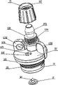
图1是本实用新型瓶盖部分立体视图。Fig. 1 is a partial perspective view of the bottle cap of the present utility model.
图2是本实用新型盖体及水管组组合状态立体视图。Fig. 2 is a perspective view of the combined state of the cover body and the water pipe group of the utility model.
图3是本实用新型使用状态主视图。Fig. 3 is a front view of the utility model in use.
图4是图3的A-A剖视图。Fig. 4 is a cross-sectional view along line A-A of Fig. 3 .
图5是本实用新型另一实施例瓶盖部分立体视图。Fig. 5 is a perspective view of another embodiment of the bottle cap of the present invention.
图6是本实用新型另一实施例瓶盖俯视图。Fig. 6 is a top view of another embodiment of the bottle cap of the present invention.
图7是图6的B-B剖视图。Fig. 7 is a B-B sectional view of Fig. 6 .
具体实施方式 Detailed ways
图1至图7中标号所示为:The labels in Figures 1 to 7 are shown as:
瓶盖1包括:内螺式盖体10,螺合部101,内螺纹1011,盖板102,止水肋1021,出水座103,提把1031;The
盖体11包括:螺合部111,外螺纹1111;盖板112,软垫圈1121,进气孔1122,扣孔1123;出水座113,吸管插孔1131,出水孔1132,护耳1133,挂钩孔11331,软胶层11332,螺接1134,外螺纹11341,锥形肋1135;The cover body 11 includes:
单向进气阀片12,扣榫121;One-way
螺接套13,内螺纹131,抵压肋132。The threaded
水管组2包括:吸水管21,硬吸管A211,斜面入水口2111;软吸管212;硬吸管B213;软导管22,吸嘴23。The
瓶体3,瓶口31,内螺纹311。
挂钩4。Hook 4.
如图1所示:本实用新型瓶盖1由一盖体11、一单向进气阀片12和一螺接套13组成,盖体11下部设一环形螺合部111,其外壁设数圈外螺纹1111,盖体11中部为一圆形盖板112,盖板112下方设一环形软垫圈1121,盖板112一侧设数个进气孔1122,进气孔1122中央设一扣孔1123;盖板112另一侧设一出水座113,出水座113外侧下部设两片护耳1133,于其中一片护耳1133上穿设一挂钩孔11331,两护耳1133外包一层软胶层11332,该软胶层11332与盖板112下方的软垫圈1121一同包射(二次注塑)成型;出水座113中部设一螺接1134,其外壁设数圈外螺纹11341,出水座113上部设一锥形肋1135与螺接环1134固接;单向进气阀片12中央凸设一扣榫121;螺接套13内壁设数圈内螺纹131、上部设一抵压肋132。As shown in Figure 1: the utility
如图2所示:本实用新型的水管组2由吸水管21、软导管22和吸嘴23组成;瓶体3的瓶口31内壁设数圈内螺纹311;吸水管21插入瓶体3内;吸嘴23连接于软导管22出水端,通过吸嘴23吸吮瓶体3内的水。As shown in Figure 2: the
如图3所示:本实用新型两片护耳1133分别设于出水座113两侧,便于旋拧盖体11;挂钩4穿入挂钩孔11331内,便于携带瓶体3。As shown in Figure 3: the utility model two pieces of
如图4所示:本实用新型的出水座113内腔下部设一吸管插孔1131贯穿于盖板112下方、吸管插孔1131上方连通一出水孔1132;吸水管21由硬吸管A 211硬吸管B 213和一段软吸管212组成,硬吸管B 213插入吸管插孔1131内,硬吸管A 211下端设一斜面入水口2111抵于瓶体3底部,软吸管212套固于硬吸管A 211和硬吸管B 213外壁,达到到调节吸管21之总长度和增加柔韧性之目的。螺合部111旋入瓶口31内,外螺纹1111和内螺纹311螺合,软垫圈1121抵压于瓶口31处可密封住瓶口31。软导管22之一端套固于锥形肋1135外,螺接套13与螺接环1134螺接时,将软导管22抵压于锥形肋1135与抵压肋132之间,确保较高的连接强度;单向进气阀片12贴附于进气孔1122下方,扣榫121扣固于扣孔1123内;吸水时,因进气孔1122能及时补充空气,防止瓶体3内产生负压,故能确保水流顺畅。As shown in Figure 4: the lower part of the
本实用新型还可通过另一方式实施:如图5所示,盖体设为一内螺式盖体10,内螺式盖体10下部设一环形螺合部101,中部为一圆形盖板102,出水座103外侧下部凸设一提把1031,提把1031另一端与盖板102固接。如图6和图7所示,螺合部101内壁设数圈内螺纹1011,盖板102下方设一环形止水肋1021。本实施例瓶盖部分的其它组件和水管组与前一实施例相同,不再详述,本实施例所述的内螺式盖体10可适配于瓶口具有外螺纹的瓶体。The utility model can also be implemented in another way: as shown in Figure 5, the cover body is set as an internal screw type cover body 10, the bottom part of the internal screw type cover body 10 is provided with an annular screw
Claims (4)
Priority Applications (1)
| Application Number | Priority Date | Filing Date | Title |
|---|---|---|---|
| CNU2007200573530U CN201119537Y (en) | 2007-09-24 | 2007-09-24 | Portable drinking water bottle cap |
Applications Claiming Priority (1)
| Application Number | Priority Date | Filing Date | Title |
|---|---|---|---|
| CNU2007200573530U CN201119537Y (en) | 2007-09-24 | 2007-09-24 | Portable drinking water bottle cap |
Publications (1)
| Publication Number | Publication Date |
|---|---|
| CN201119537Y true CN201119537Y (en) | 2008-09-24 |
Family
ID=40006752
Family Applications (1)
| Application Number | Title | Priority Date | Filing Date |
|---|---|---|---|
| CNU2007200573530U Expired - Fee Related CN201119537Y (en) | 2007-09-24 | 2007-09-24 | Portable drinking water bottle cap |
Country Status (1)
| Country | Link |
|---|---|
| CN (1) | CN201119537Y (en) |
Cited By (1)
| Publication number | Priority date | Publication date | Assignee | Title |
|---|---|---|---|---|
| CN105533996A (en) * | 2016-01-29 | 2016-05-04 | 彭攀巅 | Novel automatic gas return soft-body cup |
-
2007
- 2007-09-24 CN CNU2007200573530U patent/CN201119537Y/en not_active Expired - Fee Related
Cited By (2)
| Publication number | Priority date | Publication date | Assignee | Title |
|---|---|---|---|---|
| CN105533996A (en) * | 2016-01-29 | 2016-05-04 | 彭攀巅 | Novel automatic gas return soft-body cup |
| CN105533996B (en) * | 2016-01-29 | 2017-11-24 | 彭攀巅 | New type auto return-air soft cup |
Similar Documents
| Publication | Publication Date | Title |
|---|---|---|
| CN1110282C (en) | Drinking cup assembly and flow control element for use in a leakproof cup assembly | |
| CN210446525U (en) | Water leakage-proof sealing cup cover | |
| US20100308133A1 (en) | Rinsing Liquid Supplying Device | |
| CN201119537Y (en) | Portable drinking water bottle cap | |
| CN211862064U (en) | A sports water bottle with leak-proof function | |
| CN203461287U (en) | Air-permeable cup cover | |
| CN205813913U (en) | Drinking bottle straw closure structure | |
| TW200833567A (en) | Dispensing device of liquid chemical and dispensing method | |
| KR101565236B1 (en) | Beverage Container With Straw | |
| CN2748398Y (en) | Drinking water bottle cap and straw | |
| CN206252669U (en) | Novel seal drink bottle | |
| CN206119559U (en) | Flip straw kettle | |
| CN211243113U (en) | Portable body cleaner | |
| CN101878991B (en) | Inflatable drinking device | |
| CN207258326U (en) | A water-stop type water bag suction nozzle | |
| CN201055086Y (en) | Portable drinking water bag | |
| CN214711886U (en) | a cup lid | |
| CN204642564U (en) | Seat Curved Straw Lid | |
| CN215157257U (en) | Leakage-proof structure of spray-push insertion bottle | |
| CN217524518U (en) | Children diving cup | |
| CN204916558U (en) | A water-absorbing non-leaking bottle mouth assembly | |
| CN223365317U (en) | Cup cover and cup | |
| CN221635499U (en) | Portable assembly type suction nozzle | |
| CN206499290U (en) | Band rubber suction nozzle water glass | |
| CN223913864U (en) | A straw cup with a reflux structure |
Legal Events
| Date | Code | Title | Description |
|---|---|---|---|
| C14 | Grant of patent or utility model | ||
| GR01 | Patent grant | ||
| CF01 | Termination of patent right due to non-payment of annual fee |
Granted publication date: 20080924 Termination date: 20140924 |
|
| EXPY | Termination of patent right or utility model |