CN201113031Y - electrical connector - Google Patents
electrical connector Download PDFInfo
- Publication number
- CN201113031Y CN201113031Y CNU2007200436321U CN200720043632U CN201113031Y CN 201113031 Y CN201113031 Y CN 201113031Y CN U2007200436321 U CNU2007200436321 U CN U2007200436321U CN 200720043632 U CN200720043632 U CN 200720043632U CN 201113031 Y CN201113031 Y CN 201113031Y
- Authority
- CN
- China
- Prior art keywords
- fixture
- insulation shell
- location division
- aforementioned
- electric connector
- Prior art date
- Legal status (The legal status is an assumption and is not a legal conclusion. Google has not performed a legal analysis and makes no representation as to the accuracy of the status listed.)
- Expired - Lifetime
Links
Images


Classifications
-
- H—ELECTRICITY
- H01—ELECTRIC ELEMENTS
- H01R—ELECTRICALLY-CONDUCTIVE CONNECTIONS; STRUCTURAL ASSOCIATIONS OF A PLURALITY OF MUTUALLY-INSULATED ELECTRICAL CONNECTING ELEMENTS; COUPLING DEVICES; CURRENT COLLECTORS
- H01R12/00—Structural associations of a plurality of mutually-insulated electrical connecting elements, specially adapted for printed circuits, e.g. printed circuit boards [PCB], flat or ribbon cables, or like generally planar structures, e.g. terminal strips, terminal blocks; Coupling devices specially adapted for printed circuits, flat or ribbon cables, or like generally planar structures; Terminals specially adapted for contact with, or insertion into, printed circuits, flat or ribbon cables, or like generally planar structures
- H01R12/70—Coupling devices
- H01R12/7005—Guiding, mounting, polarizing or locking means; Extractors
- H01R12/7011—Locking or fixing a connector to a PCB
- H01R12/7064—Press fitting
-
- H—ELECTRICITY
- H01—ELECTRIC ELEMENTS
- H01R—ELECTRICALLY-CONDUCTIVE CONNECTIONS; STRUCTURAL ASSOCIATIONS OF A PLURALITY OF MUTUALLY-INSULATED ELECTRICAL CONNECTING ELEMENTS; COUPLING DEVICES; CURRENT COLLECTORS
- H01R13/00—Details of coupling devices of the kinds covered by groups H01R12/70 or H01R24/00 - H01R33/00
- H01R13/40—Securing contact members in or to a base or case; Insulating of contact members
- H01R13/405—Securing in non-demountable manner, e.g. moulding, riveting
- H01R13/41—Securing in non-demountable manner, e.g. moulding, riveting by frictional grip in grommet, panel or base
Landscapes
- Details Of Connecting Devices For Male And Female Coupling (AREA)
- Coupling Device And Connection With Printed Circuit (AREA)
Abstract
一种电连接器,包括绝缘壳体、固定于绝缘壳体的若干导电端子及两个固定件,第一固定件的基部、第一定位部及第二定位部共同组成钩状结构,该钩状结构钩在绝缘壳体隔壁上,有很好的定位效果,尤其第一固定件的基部能提供强大的作用力挡止绝缘壳体向第二面指向第一面的法向运动;而且,第一固定件的固定部不是从定位部的中部延伸出来,而是直接连接在基部一端延伸出的第二定位部上,故该位置偏向固定件的一侧,有利于将固定部偏于电连接器一侧布置。

An electrical connector, including an insulating housing, a number of conductive terminals fixed on the insulating housing, and two fixing parts, the base of the first fixing part, the first positioning part and the second positioning part together form a hook structure, the hook The shape structure is hooked on the partition wall of the insulating shell, which has a good positioning effect, especially the base of the first fixing part can provide a strong force to stop the normal movement of the insulating shell from the second surface to the first surface; and, The fixing part of the first fixing part does not extend from the middle part of the positioning part, but is directly connected to the second positioning part extending from one end of the base part, so the position is biased to one side of the fixing part, which is conducive to biasing the fixing part to the electric Connector side layout.
Description
【技术领域】 【Technical field】
本实用新型是关于一种电连接器,尤其涉及电连接器在电路板上固定的技术。The utility model relates to an electric connector, in particular to a technique for fixing the electric connector on a circuit board.
【背景技术】 【Background technique】
电连接器在电子领域应用非常广泛,在电子设备中的元件与元件、组件与组件、系统与系统之间都有运用,进行电气连接和信号传递,是构成一个完整系统所必须的基础元件。Electrical connectors are widely used in the electronic field. They are used between components and components, components and components, and systems and systems in electronic equipment. Electrical connections and signal transmission are the basic components necessary to form a complete system.
电连接器通常安装在电路板上,并可与另一个对接电连接器对接,以达成对接电连接器与电路板上的电子元件电性连通。请参照2004年5月21日公告的中国台湾新型专利公告第588867号,其中第七图揭示了一种电连接器,该电连接器具有长形的绝缘壳体,绝缘壳体长度延伸方向的相对两端对称装设有固定件14,该固定件14下端比较细从上向下穿透绝缘壳体并突出在底面外形成固定部142,可以焊接固定在电路板3上的穿孔32中,上端有个部位比较大形成定位部141,可以卡定在绝缘壳体上,这样固定件可加强电连接器在电路板3上的固定效果。The electrical connector is usually installed on the circuit board, and can be docked with another mating electrical connector, so as to achieve electrical communication between the mating electrical connector and the electronic components on the circuit board. Please refer to the Chinese Taiwan New Patent Announcement No. 588867 announced on May 21, 2004, in which the seventh figure discloses an electrical connector, which has an elongated insulating shell, and the length of the insulating shell in the direction of extension
但是,一方面,由于电连接器本身的结构并非绝对对称,比如,中国台湾新型专利公告第588867号第七图中电连接器的插接部12一端设有向一侧凸出的防呆凸块122,这样在与对接的电连接器插接时,存在受力不均衡情况,一侧受大,另一侧受力小,固定件对称设置不利于应对不均衡的受力情况,反而容易被外力破坏;另一方面,电路上会安装许多电子元件,该电子元件需要合理布局,基于电路布局的要求,电路板上有的部位不允许打孔,一旦电连接器的对称部位不允许打孔,固定件的固定部便不能对称地设置电连接器上。However, on the one hand, since the structure of the electrical connector itself is not absolutely symmetrical, for example, one end of the plug-in
因此,需要提供一种能够减少或消除上述缺点的电连接器。Therefore, it is necessary to provide an electrical connector capable of reducing or eliminating the above disadvantages.
【实用新型内容】【Content of utility model】
因此,本实用新型要解决的技术问题是固定件的固定部便于偏向电连接器一侧设置。Therefore, the technical problem to be solved by the utility model is that the fixing portion of the fixing member is conveniently arranged on one side of the electrical connector.
本实用新型电连接器,包括绝缘壳体、固定于绝缘壳体的若干导电端子及两个固定件,该绝缘壳体具有相对的第一端部与第二端部,并于第一端部与第二端部之间设有相对的第一面及第二面,第一面中部向远离第二面方向突出延伸有插接板,插接板具有接合面及与该接合面相对的背面,导电端子包括接触部及安装部,这些接触部并列于插接板的接合面,安装部从绝缘壳体第二面向远离第一面的方向延伸出,该两个固定件中的第一固定件定位于绝缘壳体的第一端部,第二固定件定位于第二端部,每一个固定件具有定位于绝缘壳体的定位部及从绝缘壳体第二面向远离第一面的方向延伸出的固定部,其中,第一固定件的定位部包括一个靠近第一面横向延伸的基部,基部包括相对的第一端及第二端,自基部第一端向靠近第二面方向延伸出第一定位部,自基部第二端向靠近第二面方向延伸出第二定位部,前述固定部则自该第二定位部相对基部的另一端延伸出,前述第一固定件的第一定位部与第二定位部之间形成间隙,而绝缘壳体对应该间隙的位置设有隔壁。The electrical connector of the utility model comprises an insulating shell, a plurality of conductive terminals fixed on the insulating shell and two fixing parts, the insulating shell has a first end and a second end opposite to each other, and the first end A first surface and a second surface opposite to the second end are provided. A plug board protrudes from the middle of the first face away from the second face. The plug board has a joint surface and a back surface opposite to the joint surface. , the conductive terminal includes a contact portion and a mounting portion, and these contact portions are arranged in parallel on the joint surface of the plug board, the mounting portion extends from the second surface of the insulating housing in a direction away from the first surface, and the first fixing part of the two fixing parts The fixing part is positioned at the first end of the insulating housing, and the second fixing part is positioned at the second end. Each fixing part has a positioning part positioned at the insulating housing and a direction away from the first surface from the second surface of the insulating housing. The extended fixing portion, wherein the positioning portion of the first fixing member includes a base extending laterally close to the first surface, the base includes opposite first ends and second ends, and extends from the first end of the base toward the direction close to the second surface Out of the first positioning part, a second positioning part extends from the second end of the base to the direction close to the second surface, and the aforementioned fixing part extends from the other end of the second positioning part opposite to the base, and the first positioning part of the aforementioned first fixing part A gap is formed between the positioning part and the second positioning part, and a partition wall is provided at a position corresponding to the gap in the insulating housing.
与现有技术相比,本实用新型电连接器的第一固定件的基部、第一定位部及第二定位部共同组成钩状结构,该钩状结构钩在绝缘壳体隔壁上,有很好的定位效果,尤其第一固定件的基部能提供强大的作用力挡止绝缘壳体向第二面指向第一面的法向运动;而且,第一固定件的固定部不是从定位部的中部延伸出来,而是直接连接在基部一端延伸出的第二定位部上,故该位置偏向固定件的一侧,方便因应电连接器受力不均衡的情况或者因应电路板的布局要求,将固定部偏向电连接器一侧布置。Compared with the prior art, the base of the first fixing part, the first positioning part and the second positioning part of the electrical connector of the utility model jointly form a hook-shaped structure, and the hook-shaped structure is hooked on the partition wall of the insulating housing, which has a large Good positioning effect, especially the base of the first fixing part can provide a strong force to stop the normal movement of the insulating shell from the second surface to the first surface; moreover, the fixing part of the first fixing part is not from the positioning part The middle part extends out, but is directly connected to the second positioning part extended from one end of the base, so the position is biased to one side of the fixing part, which is convenient for responding to the unbalanced force of the electrical connector or the layout requirements of the circuit board. The fixing part is arranged toward one side of the electrical connector.
【附图说明】 【Description of drawings】
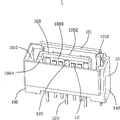
图1为本实用新型电连接器立体图;Figure 1 is a perspective view of the utility model electrical connector;
图2为图1电连接器另一角度的立体图;Fig. 2 is a perspective view of another angle of the electrical connector of Fig. 1;
图3为图1电连接器前视图;Fig. 3 is a front view of the electrical connector of Fig. 1;
图4为图1电连接器俯视图;Fig. 4 is a top view of the electrical connector in Fig. 1;
图5为图1电连接器仰视图;Fig. 5 is a bottom view of the electrical connector of Fig. 1;
图6为沿图4中A-A线的剖视图;Fig. 6 is a sectional view along line A-A in Fig. 4;
图7为沿图4中B-B线的剖视图。Fig. 7 is a sectional view along line B-B in Fig. 4 .
【具体实施方式】 【Detailed ways】
请参照图1到图7所示,一种电连接器1,包括长形绝缘壳体10、固定于绝缘壳体10的若干导电端子12及两个固定件14、16。Referring to FIGS. 1 to 7 , an
该绝缘壳体10长度延伸方向之两端各具有相对的第一端部100与第二端部102,平行长度延伸方向具有相对的第一面104及第二面106,第一面104中部向远离第二面106方向突出延伸有长形插接板108,插接板108具有平行长度延伸方向的接合面1080及与该接合面1080相对的背面1082。沿插接板1082靠近绝缘壳体10第一端部100的边缘有一个凸块1084,该凸块1084从接合面1080向远离背面1082方向突出,可以帮助识别电连接器1的方向,与对接的电连接器(未图示)的相应结构配合达成防误插作用。插接板108背面1082设有扣持槽1086,可卡止对接的电连接器(未图示)的相应扣持钩,共同作用保持两对接电连接器的对接状态,该扣持槽1086从插接板108背面1082中部向绝缘壳体10第一面104延伸,并贯穿到第二面106,在利用模具(未图示)用塑性材料制造绝缘壳体10时,有利于简化模具(未图示)结构。The two ends of the length extension direction of the
绝缘壳体10第一面104周边还设有向远离第二面106方向延伸的围墙101,可以协助导引对接的电连接器(未图示)插接,同时保护插接板108及插接板108上的导电端子12不受损坏,并防止导电端子12被其他导电体(未图示)碰触而造成电路短路。靠近绝缘壳体10第一端100的围墙101内侧设有第一凹槽1010,靠近绝缘壳体10第二端102的围墙101内侧设有第二凹槽1012,第一凹槽1010宽度大于第二凹槽1012,也可以帮助识别电连接器1的方向,与对接的电连接器(未图示)的相应结构配合达成防误插作用。The surrounding
导电端子12包括接触部120及安装部122,这些接触部120并列于插接板108的接合面1080,用于与对接的电连接器(未图示)的导电端子电性接触,安装部122从绝缘壳体10第二面106向远离第一面104的方向延伸出,用于在电路板(未图示)上焊接安装。The
两个固定件14、16中的第一固定件14定位于绝缘壳体的第一端部100,第二固定件16定位于第二端部102,而且第一固定件14位于第一凹槽1010内,第二固定件16位于第二凹槽1012内。每一个固定件14、16具有定位于绝缘壳体10的定位部140、160及从绝缘壳体10第二面106向远离第一面104的方向延伸出的固定部142、162,固定部142、162用于在电路板(未图示)上固定,定位部140、160用于在绝缘壳体10上定位,并在安装以后限制绝缘壳体10不在外力作用下移动。固定件14、16是平面状金属板材冲压制成,定位部140、160冲压有突出金属板材平面的凸点144、164。Among the two
请特别参照图6所示,第一固定件14的定位部140包括一个大致平行且靠近第一面104横向延伸的基部146,基部146包括相对的第一端1460及第二端1462,自基部146第一端1460向靠近第二面106方向延伸出第一定位部1400,自基部146第二端1462向靠近第二面106方向延伸出第二定位部1402。凸点144设置在基部146与第一定位部1400相连的部位附近,有利于将固定件14稳定地定位在绝缘壳体10上。固定部142则自该第二定位部1402相对基部146的另一端延伸出,前述第一固定件14的第一定位部1400与第二定位部1402之间形成间隙,而绝缘壳体10对应该间隙的位置设有隔壁109。由于第一固定件14的基部146、第一定位部1400及第二定位部1402共同组成钩状结构,该钩状结构钩在绝缘壳体10的隔壁109上,有很好的定位效果,尤其第一固定件14的基部146能提供强大的作用力挡止绝缘壳体10向第二面106指向第一面104的法向运动;而且,第一固定件14的固定部142不是从定位部140的中部延伸出来,而是直接连接在基部146一端延伸出的第二定位部1402上,故该位置偏向固定件14的一侧,方便因应电连接器受力不均衡的情况或者因应电路板的布局要求,将固定部142偏向电连接器1的一侧布置。Please refer to FIG. 6 in particular. The positioning portion 140 of the
请特别参照图7所示,第二固定件16的定位部160比固定部162大,可以卡止定位在绝缘壳体10上,凸点164设置在定位部160中部附近,有利于将固定件16稳定定位在绝缘壳体10上。固定部162连接到定位部160靠近绝缘壳体10第二面106的边缘,且固定部162的中轴线与定位部160的中轴线重合,这样在外力作用下第二固定件16受力会比较均衡。Please refer to FIG. 7 in particular. The positioning part 160 of the
第一固定件14与第二固定件16的固定部142、162在一个中间部位均稍弯折而拱起,形成扭结部1420、1620,在安装电连接器1时,该扭结部1420、1620可以卡止在电路板(未图示)上的相应小孔中,使电连接器1在焊接前能定位在电路板(未图示)上,方便安装操作。请特别参照图1及图3所示,第一固定件14的扭结部1420拱起的方向与第二固定件16的扭结部1620拱起的方向是相反的,这样,扭结部1420在电路板(未图示)上的相应小孔中的卡止效果会比较好。请特别参照图1、图4及图5所示,绝缘壳体10上对应该扭结部1420、1620拱起的部位挖空设置通槽107,该通槽107从绝缘壳体10第一面104贯通至第二面106,且在扭结部1420、1620拱起方向的深度大于扭结部1420、1620拱起的高度,扭结部1420、1620正好可以通过该通槽107,这样在安装固定件14、16时,可以沿第一面104指向第二面106的法向方向将固定件14、16顺利装入绝缘壳体10。The fixing
请特别参照图1及图5所示,至少有部分前述导电端子12的安装部122相对于接触部120有偏离,而使部分安装部122之间的距离大于相应导电端子12的接触部120之间的距离,安装部122之间的距离较大有利于电路板(未图示)之布局,而且有利于减小导电端子12之间的电信号干扰。Please refer to FIG. 1 and FIG. 5 in particular, at least some of the mounting
Claims (10)
Priority Applications (2)
| Application Number | Priority Date | Filing Date | Title |
|---|---|---|---|
| CNU2007200436321U CN201113031Y (en) | 2007-10-12 | 2007-10-12 | electrical connector |
| US12/287,903 US7682190B2 (en) | 2007-10-12 | 2008-10-14 | Electrical connector having board lock |
Applications Claiming Priority (1)
| Application Number | Priority Date | Filing Date | Title |
|---|---|---|---|
| CNU2007200436321U CN201113031Y (en) | 2007-10-12 | 2007-10-12 | electrical connector |
Publications (1)
| Publication Number | Publication Date |
|---|---|
| CN201113031Y true CN201113031Y (en) | 2008-09-10 |
Family
ID=39964774
Family Applications (1)
| Application Number | Title | Priority Date | Filing Date |
|---|---|---|---|
| CNU2007200436321U Expired - Lifetime CN201113031Y (en) | 2007-10-12 | 2007-10-12 | electrical connector |
Country Status (2)
| Country | Link |
|---|---|
| US (1) | US7682190B2 (en) |
| CN (1) | CN201113031Y (en) |
Cited By (2)
| Publication number | Priority date | Publication date | Assignee | Title |
|---|---|---|---|---|
| CN103365348A (en) * | 2012-04-06 | 2013-10-23 | 鸿富锦精密工业(深圳)有限公司 | Main board provided with electronic hard disk |
| CN104283027A (en) * | 2013-07-08 | 2015-01-14 | 达矿科技股份有限公司 | Connector with a locking member |
Families Citing this family (3)
| Publication number | Priority date | Publication date | Assignee | Title |
|---|---|---|---|---|
| CN201829767U (en) * | 2010-04-26 | 2011-05-11 | 富士康(昆山)电脑接插件有限公司 | Plug connector and socket connector in butt joint with same |
| JP7482021B2 (en) * | 2020-12-25 | 2024-05-13 | 日本航空電子工業株式会社 | Electrical component |
| US11923629B2 (en) * | 2021-12-13 | 2024-03-05 | Mellanox Technologies Ltd. | Device connectable to a printed circuit board with high precision |
Family Cites Families (15)
| Publication number | Priority date | Publication date | Assignee | Title |
|---|---|---|---|---|
| US5409399A (en) * | 1993-12-08 | 1995-04-25 | Molex Incorporated | Electrical connection assembly for mounting on a printed circuit board |
| US5755595A (en) * | 1996-06-27 | 1998-05-26 | Whitaker Corporation | Shielded electrical connector |
| JP3330559B2 (en) * | 1999-03-15 | 2002-09-30 | 日本圧着端子製造株式会社 | Printed wiring board connector |
| JP2002023026A (en) * | 2000-07-07 | 2002-01-23 | Yazaki Corp | Optical connector |
| US6406320B1 (en) * | 2001-04-17 | 2002-06-18 | Hon Hai Precision Ind. Co., Ltd. | Electrical connector with latch |
| TW588867U (en) | 2001-07-25 | 2004-05-21 | Molex Taiwan Ltd | Serial ATA electrical connector |
| TW509393U (en) * | 2001-10-18 | 2002-11-01 | Molex Inc | Electrical connector |
| JP4120198B2 (en) * | 2001-10-24 | 2008-07-16 | モレックス インコーポレーテッド | Board connector |
| US20030181096A1 (en) * | 2002-03-21 | 2003-09-25 | Kuon Yi Industrial Corp. | Structure of connector outer shell |
| JP2004039742A (en) * | 2002-07-01 | 2004-02-05 | Tokai Rika Co Ltd | Temporary fixing parts |
| US6589074B1 (en) * | 2002-07-31 | 2003-07-08 | Hon Hai Precision Ind. Co., Ltd. | Two ports integral electrical connector |
| TW549634U (en) * | 2002-11-15 | 2003-08-21 | Hon Hai Prec Ind Co Ltd | Electrical connector |
| US6960089B2 (en) * | 2003-08-01 | 2005-11-01 | Hon Hai Precision Ind. Co., Ltd | Serial ATA connector with right angle contact |
| JP4007970B2 (en) * | 2004-03-30 | 2007-11-14 | 日本航空電子工業株式会社 | Connector fixing member and connector using the same |
| CN200972951Y (en) * | 2006-10-16 | 2007-11-07 | 富士康(昆山)电脑接插件有限公司 | Electric connector |
-
2007
- 2007-10-12 CN CNU2007200436321U patent/CN201113031Y/en not_active Expired - Lifetime
-
2008
- 2008-10-14 US US12/287,903 patent/US7682190B2/en not_active Expired - Fee Related
Cited By (2)
| Publication number | Priority date | Publication date | Assignee | Title |
|---|---|---|---|---|
| CN103365348A (en) * | 2012-04-06 | 2013-10-23 | 鸿富锦精密工业(深圳)有限公司 | Main board provided with electronic hard disk |
| CN104283027A (en) * | 2013-07-08 | 2015-01-14 | 达矿科技股份有限公司 | Connector with a locking member |
Also Published As
| Publication number | Publication date |
|---|---|
| US20090098751A1 (en) | 2009-04-16 |
| US7682190B2 (en) | 2010-03-23 |
Similar Documents
| Publication | Publication Date | Title |
|---|---|---|
| US20200161811A1 (en) | Connector having metal shell with anti-displacement structure | |
| CN100576647C (en) | Electrical connector assembly | |
| CN2917029Y (en) | electrical connector | |
| CN102263334B (en) | Electrical connector | |
| CN203326274U (en) | Electric connector | |
| CN100585953C (en) | Board-to-Board Connector | |
| CN103066418A (en) | Switch-equipped coaxial connector | |
| CN201207538Y (en) | speaker connector | |
| CN104979684A (en) | Socket connector | |
| CN201113031Y (en) | electrical connector | |
| CN116345200A (en) | Connector and connector assembly including the same | |
| CN102623825A (en) | Audio connector | |
| CN103972730B (en) | Electric connector | |
| CN201112870Y (en) | battery connector | |
| CN209298392U (en) | Flexible soft board electrical connector assembly | |
| CN207098149U (en) | Board-to-board electric connector assembly and socket connector and plug connector thereof | |
| CN201352617Y (en) | Board-to-Board Connector | |
| CN201562777U (en) | Electric connector with locking mechanism | |
| US9431736B2 (en) | Card edge connector and card edge connector assembly | |
| CN201498808U (en) | Electrical connector | |
| CN2689500Y (en) | Assembly of electric connector | |
| CN201440504U (en) | Electric connector | |
| CN201142395Y (en) | Conductive terminals and electrical connectors | |
| CN207459276U (en) | Electric connector and electronic equipment | |
| CN214478052U (en) | Electric connector |
Legal Events
| Date | Code | Title | Description |
|---|---|---|---|
| C14 | Grant of patent or utility model | ||
| GR01 | Patent grant | ||
| CX01 | Expiry of patent term | ||
| CX01 | Expiry of patent term |
Granted publication date: 20080910 |