CN201093331Y - Light distribution energy-saving lampshade - Google Patents
Light distribution energy-saving lampshade Download PDFInfo
- Publication number
- CN201093331Y CN201093331Y CNU200720178620XU CN200720178620U CN201093331Y CN 201093331 Y CN201093331 Y CN 201093331Y CN U200720178620X U CNU200720178620X U CN U200720178620XU CN 200720178620 U CN200720178620 U CN 200720178620U CN 201093331 Y CN201093331 Y CN 201093331Y
- Authority
- CN
- China
- Prior art keywords
- light
- lampshade
- angle
- mentioned
- transmitting plate
- Prior art date
- Legal status (The legal status is an assumption and is not a legal conclusion. Google has not performed a legal analysis and makes no representation as to the accuracy of the status listed.)
- Expired - Fee Related
Links
- 238000009826 distribution Methods 0.000 title claims abstract description 24
- 230000000694 effects Effects 0.000 claims abstract description 12
- 230000003287 optical effect Effects 0.000 claims description 4
- 238000009827 uniform distribution Methods 0.000 claims description 4
- 230000000149 penetrating effect Effects 0.000 claims 1
- 230000004313 glare Effects 0.000 abstract description 8
- NIXOWILDQLNWCW-UHFFFAOYSA-N acrylic acid group Chemical group C(C=C)(=O)O NIXOWILDQLNWCW-UHFFFAOYSA-N 0.000 description 3
- 238000010586 diagram Methods 0.000 description 3
- 238000005286 illumination Methods 0.000 description 2
- 238000000034 method Methods 0.000 description 2
- 241001465382 Physalis alkekengi Species 0.000 description 1
- 238000000889 atomisation Methods 0.000 description 1
- 230000009286 beneficial effect Effects 0.000 description 1
- 238000009795 derivation Methods 0.000 description 1
- 230000007613 environmental effect Effects 0.000 description 1
Images

Landscapes
- Illuminated Signs And Luminous Advertising (AREA)
Abstract
一种光分布节能灯罩是由一上方灯罩主体结合下方一透光板材,灯罩内部装置一聚光罩与一光分布曲线反光罩,一个以上发光体,发光体正下方设一锥形体反光物;当点亮发光体时,能使灯罩内照射出的光线均匀分布在照射区域,不会产生直射区域特别明亮的高斯分布现象达到节能效果,且避免在任何角度眼睛会直接看到发光体强光而产生眩光现象。
A light distribution energy-saving lampshade is composed of an upper lampshade main body combined with a lower light-transmitting plate, a focusing cover and a light distribution curve reflector cover are arranged inside the lampshade, and one or more light-emitting bodies are arranged with a cone-shaped reflector directly below the light-emitting bodies. When the light-emitting bodies are lit, the light emitted from the lampshade can be evenly distributed in the irradiated area, and the Gaussian distribution phenomenon in which the direct irradiation area is particularly bright will not be generated to achieve energy-saving effects, and glare can be avoided when the eyes directly see the strong light of the light-emitting body at any angle.
Description
技术领域technical field
本新型关于一种灯罩,尤其是光分布节能灯罩。The present invention relates to a lampshade, in particular to a light distribution energy-saving lampshade.
背景技术Background technique
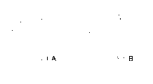
照明灯具一般分为室内与室外用二种,室内用灯具以半罩式为主(请参图1A),主要在光源102上方装设一半罩式不透光罩体101,罩体内侧表面103具反光效果,此类灯具为避免光源对眼睛产生刺眼与眩光情况,通常在光源表面做雾化处理降低前述现象。室外用灯具因考虑环境因素皆以全罩式灯罩(请参图1B)为主,其下方透光灯罩104也是一样做雾化处理避免眼睛直视光源的眩光现象,此二者皆有损失很多亮度及光线仅集中于光源正下方局部区域的缺点。Lighting lamps are generally divided into two types: indoor and outdoor. Indoor lamps are mainly half-covered (please refer to FIG. 1A ). With reflective effect, in order to avoid the glare and glare caused by the light source to the eyes, this kind of lamp is usually atomized on the surface of the light source to reduce the above phenomenon. Due to consideration of environmental factors, outdoor lamps and lanterns are mainly full-cover lampshades (please refer to Figure 1B), and the light-transmitting
发明内容Contents of the invention
本实用新型目的在于,提供一种光分布节能灯罩,为改善习用灯罩照明区域内光源正下方局部区域较亮,离光源较远的区域较暗的照明亮度不均匀问题。The purpose of the utility model is to provide an energy-saving lampshade with light distribution, in order to improve the uneven illumination brightness problem that the local area directly below the light source in the lighting area of the conventional lampshade is brighter and the area farther away from the light source is darker.
根据上述目的,本实用新型一种光分布节能灯罩,包括:According to the above purpose, the utility model provides a light distribution energy-saving lampshade, comprising:
一灯罩主体,灯罩主体内装置至少一个以上连接电源线的灯座;A main body of the lampshade, at least one lamp socket connected to the power cord is installed in the main body of the lampshade;
一个以上通过上述灯座取得电源而发光的发光体,装置于上述灯罩主体内的灯座上;其特征在于:More than one luminous body that obtains power through the above-mentioned lamp holder and emits light is installed on the lamp holder in the main body of the above-mentioned lampshade; it is characterized in that:
一聚光罩,其顶部开设有一供上述发光体穿过的穿孔;A condensing cover, the top of which is provided with a perforation for the above-mentioned luminous body to pass through;
一反光罩,固定设置于灯罩主体内与聚光罩密合连接,其内侧面由数平面连接成一光分布曲线形而构成,该每一平面尺寸、角度由入射光线照射该平面时要将该入射光线反射至某特定区块的反射光线所形成的夹角,依据反射定律「入射角=反射角」及「法线垂直于平面」原理,设定该平面与水平面之相对角度与尺寸;A reflector, which is fixedly arranged in the main body of the lampshade and closely connected with the condenser cover, and its inner surface is composed of several planes connected to form a light distribution curve. The size and angle of each plane should be the The included angle formed by the reflected light reflected from the incident light to a specific block, according to the law of reflection "incident angle = reflection angle" and the principle of "normal line perpendicular to the plane", set the relative angle and size of the plane and the horizontal plane;
一透光板材,设置于上述灯罩主体光线照明端;及A light-transmitting plate is arranged at the light-emitting end of the main body of the above-mentioned lampshade; and
一锥形体反光物设置于上述透光板材内侧,锥顶朝向上述发光体中心;A cone-shaped reflector is arranged on the inner side of the above-mentioned light-transmitting plate, and the top of the cone faces the center of the above-mentioned illuminant;
上述聚光罩将上述发光体之光线聚光于下方之上述锥形体反光物表面,再将光线反射至上述反光罩;上述光分布曲线反光罩,将光线反射到预定照射区块,达到照明区域亮度均匀分布的效果;且上述锥形体反光物使部份光线经二次以上反射再投射到欲照明区块,控制光线照射到某一特定区块。The condensing cover condenses the light of the illuminant on the surface of the above-mentioned conical reflector below, and then reflects the light to the above-mentioned reflector; the above-mentioned light distribution curve reflector reflects the light to the predetermined irradiation area to reach the lighting area The effect of uniform distribution of brightness; and the above-mentioned conical reflector makes part of the light reflected more than twice and then projected to the block to be illuminated, so as to control the light to irradiate a specific block.
其中:透光板材具有数临界角,且至少有一面是数光栅,光栅的间隙、角度、规格、形状依据该透光板材材质之光学临界角原理设计,控制上述发光体直接入射光线之入射角大于该临界角成全反射而不直接穿透该透光板材,其它非由上述发光体直接入射光线之入射角小于该临界角而直接穿透该透光板材。Among them: the light-transmitting plate has a digital critical angle, and at least one side is a digital grating. The gap, angle, specification, and shape of the grating are designed according to the optical critical angle principle of the light-transmitting plate material, and the incident angle of the direct incident light of the above-mentioned luminous body is controlled. If the incident angle is greater than the critical angle, it will be totally reflected and will not directly pass through the light-transmitting plate. Other light rays that are not directly incident by the above-mentioned luminous body will directly pass through the light-transmitting plate if the incident angle is smaller than the critical angle.
其中,透光板材为一圆形环状光栅。Wherein, the light-transmitting plate is a circular ring-shaped grating.
其中,透光板材为一方形条状光栅。Wherein, the light-transmitting plate is a square strip grating.
其中,聚光罩为抛物曲线形。Wherein, the condenser is in the shape of a parabolic curve.
其中,聚光罩为部份椭圆曲线形。Wherein, the condensing cover is partly elliptic curve.
本实用新型有益效果:Beneficial effects of the utility model:
根据本实用新型,特别在灯罩内装置一个抛物曲线或部份椭圆曲线聚光罩,可将光线聚光于下方一锥形体反光物表面,一光分布曲线反光罩,由数平面以特定的角度排列组合而成,可将光反射到预定照射区块,达到照明区域亮度均匀分布的效果,一位于光源正下方的锥形体反光物,使部份光线经二次以上反射再投射到欲照明区块,如此更能精准控制光线照射到某一特定区块。According to the utility model, a parabolic curve or a partial elliptic curve concentrating cover is specially installed in the lampshade, which can condense the light on the surface of a conical reflector below, and a light distribution curve reflector. Arranged and combined, it can reflect light to the predetermined irradiation area to achieve the effect of uniform distribution of brightness in the illuminated area. A conical reflector located directly under the light source makes part of the light reflected twice or more and then projected to the area to be illuminated block, so that the light can be more precisely controlled to hit a specific block.
为改善习用灯罩在出光面以雾化处理透光罩表面避免眼睛眩光而造成亮度损失问题,特以一透光板材为照明面罩体,此透光板材的某一个表面可具有数不同角度排列的光栅,这些光栅可控制光线通过此透光板材时某些特定角度射入的光线入射角恒大于该透明物的临界角,使该光线呈全反射效用,这能避免在任何角度眼睛会直视到光源亮点产生炫光效应,又几乎不使透射出透明物的光线亮度减弱,达到节能效果。In order to improve the problem of brightness loss caused by fogging the surface of the light emitting surface of the conventional lampshade to avoid eye glare, a light-transmitting plate is used as the lighting mask body. A certain surface of the light-transmitting plate can have several different angles. Gratings, these gratings can control the incident angle of light at certain specific angles when the light passes through the transparent plate is always greater than the critical angle of the transparent object, so that the light is fully reflected, which can prevent the eyes from looking directly at any angle The glare effect will be produced at the bright spot of the light source, and the brightness of the light transmitted through the transparent object will hardly be weakened, so as to achieve the effect of energy saving.
附图说明Description of drawings
图1A表示一种习知半罩式灯具的示意图,Fig. 1A shows a schematic diagram of a conventional half-shade lamp,
图1B表示一种习知全罩式灯具的示意图,Fig. 1B shows a schematic diagram of a conventional full cover lamp,
图2表示本发明的第一实施例的剖面图,Fig. 2 shows the sectional view of the first embodiment of the present invention,
图3表示图2的本发明第一实施例光分布曲线反光罩某放大显示段,Fig. 3 shows a certain enlarged display section of the light distribution curve reflector of the first embodiment of the present invention shown in Fig. 2,
图4表示图2中透光板材为一圆形环状光栅板的平面图,Fig. 4 shows the plane view that the light-transmitting plate in Fig. 2 is a circular annular grating plate,
图4A表示图4的侧视图,Figure 4A shows a side view of Figure 4,
图4B表示图4A中B部分的放大视图,Figure 4B shows an enlarged view of part B in Figure 4A,
图5表示图2中透光板材为一方形条状光栅板的平面图,Fig. 5 shows that the light-transmitting plate in Fig. 2 is a plan view of a square strip grating plate,
图5A表示图5的侧视图,Figure 5A shows a side view of Figure 5,
图5B表示图5A中B部分的放大视图,Figure 5B shows an enlarged view of part B in Figure 5A,
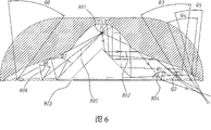
图6表示本发明光线射出的示意图,Fig. 6 shows the schematic diagram of the light emission of the present invention,
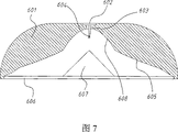
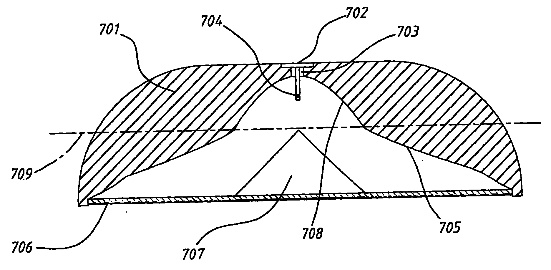
图7表示本发明另一种实施例的剖面视图。Fig. 7 shows a cross-sectional view of another embodiment of the present invention.
具体实施方式Detailed ways
请参考图2,为本发明的第一实施例,其中灯罩主体701的罩体上开设有一穿孔702,其内部装置一灯座703,并将一发光体704装置于该灯座703上取得电源而发光。Please refer to Fig. 2, which is the first embodiment of the present invention, in which a perforation 702 is opened on the cover body of the lampshade main body 701, a lamp holder 703 is installed inside it, and a luminous body 704 is installed on the lamp holder 703 to obtain power And glow.
灯罩主体701内部,在虚线709以上部份,形成一聚光罩708,其可为抛物曲线或部份椭圆曲线,而本图例以抛物曲线显示。聚光罩708顶部也开设有一穿孔,供固定于灯罩主体701内的发光体704穿过。Inside the lampshade main body 701, a spotlight 708 is formed above the dotted line 709, which can be a parabolic curve or a partial elliptic curve, and this illustration shows a parabolic curve. A perforation is also provided on the top of the light collecting cover 708 for the illuminant 704 fixed in the main body 701 of the lamp cover to pass through.
灯罩主体701内部,在虚线709以下部份,形成一光分布曲线反光罩705,其系被固定于灯罩主体内与聚光罩708连接。Inside the lampshade main body 701 , at the part below the dotted line 709 , a light distribution curve reflector 705 is formed, which is fixed in the lampshade main body and connected with the condensing cover 708 .
灯罩主体701下方,以活动装置一透光板材706,该透光板材706装置于灯罩主体光线照明端,并将一锥形体反光物707固定装置于该透光板材706内侧;该锥形体反光物707的锥顶朝向发光体704。而抛物线聚光罩708,可将发光体704照射光线聚光于下方锥形体反光物707使光线折射到反光罩705再折射出照明区域。Below the lampshade main body 701, a light-transmitting
光分布曲线反光罩705是由数平面连接组合而成曲线,这些平面的尺寸及角度都依据入射光线与在该平面欲反射至某特定区块的反射线所形成的夹角,并由光学反射原理计算出此平面与水平线相对角度与尺寸。The light distribution curve reflector 705 is a curve formed by connecting several planes. The size and angle of these planes are based on the angle formed by the incident light and the reflection line to be reflected to a specific block on the plane, and is determined by optical reflection. The principle calculates the relative angle and size of this plane and the horizontal line.
举例说明之,请参考图3,系为光分布曲线反光罩705某放大显示段203,一固定方向入射光线107要经其中一平面105表面反射至一特定欲照明区块114时,入射光线107与反射光线108形成一夹角f117;依据反射原理利用导推法计算出:f11÷2=入射角a115=反射角b116,此可定位法线113正确角度,又法线是垂直于平面105,即可定出平面105相对水平线111的角度e112。For example, please refer to FIG. 3 , which is an enlarged
透光板材706具有数临界角,且至少有一面是数光栅,光栅的间隙、角度、规格、形状依据该透光板材706材质的光学临界角原理设计,控制发光体704直接入射光线的入射角大于该临界角成全反射而不直接穿透该透光板材,其它非由发光体704直接入射光线的入射角小于该临界角而直接穿透该透光板材。The light-transmitting
请参考图4及图4A,在图2中的透光板材706可为一圆形环状光栅板401。参见图4B,圆形环状光栅板401其中一面设置数环状光栅403,另一面也可为光栅或者可为平面402,本图例以平面显示。Please refer to FIG. 4 and FIG. 4A , the
请参考图5及图5A,在图2中的透光板材706也可为一方形条状光栅板501。参见图5B,条状光栅板501其中一面设置数条状光栅503,另一面可为光栅亦可为平面502,本图例以平面显示。Please refer to FIG. 5 and FIG. 5A , the
在图4及图5中所显示的两种不同形状透光板材的光栅间距、角度、形状不尽相同,其正确数据是依据每一道不同角度入射光线照射此光栅时控制其为可穿透或为全反射;当要使光线为可穿透时,设计使其光线入射角小于该透光板材的临界角折射出光栅;反之,要使光线不可穿透时,设计使其光线入射角大于该透光板材的临界角呈全反射。The grating spacing, angle, and shape of the two different shapes of light-transmitting plates shown in Figure 4 and Figure 5 are not the same. The correct data is based on the control of whether the grating is permeable or permeable when the incident light rays at different angles irradiate the grating. It is total reflection; when the light is to be permeable, the design is to make the light incident angle smaller than the critical angle of the light-transmitting plate to refract the grating; otherwise, to make the light impenetrable, the design is to make the light incident angle larger than the The critical angle of the light-transmitting plate is total reflection.
举例说明之,请参见图6,压克力透光板材803的临界角为42.15°的。而从光源801照射出的其中一道光线802经二次反射到透明压克力材质板材803平面时产生折射,到板材803另一面光栅时入射角θ1 804为41.75°,因其小于临界角42.15°,所以再一次折射出板材803进入照明区域;其他光线入射角θ2至θ5分别为37.72°、38.91°、28.34°、22.64°,皆小于临界角42.15°,故皆再一次折射出板材803进入照明区域。For example, please refer to FIG. 6 , the critical angle of the
而从光源801照射出的另一道光线805到达透明压克力材质板材803平面时产生折射,到板材803另一面光栅时入射角θ6 806为42.83°,因其大于临界角42.15°,所以呈全反射状态不会直接穿透板材进入照明区域;其他光线入射角θ7及θ8分别为43.46°及42.72°,皆大于临界角42.15°,所以呈全反射状态不会直接穿透板材进入照明区域。Another
由图6中的解释,可知本发明在灯罩内装置抛物曲线或部份椭圆曲线聚光罩708,可将光线聚光于下方锥形体反光物707表面;而光分布曲线反光罩705,由数平面以特定的角度排列组合而成,可将光反射到预定照射区块,达到照明区域亮度均匀分布的效果;且位于光源正下方的锥形体反光物707使部份光线经二次以上反射再投射到欲照明区块,如此更能精准控制光线照射到某一特定区块。From the explanation in Fig. 6, it can be known that the present invention installs a parabolic curve or a part of the elliptic curve concentrator 708 in the lampshade, which can focus the light on the surface of the conical body reflector 707 below; The plane is arranged and combined at a specific angle, which can reflect the light to the predetermined irradiation area to achieve the effect of uniform distribution of brightness in the illuminated area; and the conical reflector 707 located directly under the light source makes part of the light reflected twice or more and then Projected to the area to be illuminated, so that the light can be more precisely controlled to hit a specific area.
另外,透光板材706为照明面罩体,此透光板材的某一个表面具有数不同角度排列的光栅,这些光栅可控制光线通过此透光板材706时某些特定角度射入的光线入射角恒大于该透明物的临界角,使该光线呈全反射效用,这能避免在任何角度眼睛会直视到光源亮点产生炫光效应,又几乎不使透射出透明物的光线亮度减弱,达到节能效果。In addition, the light-transmitting
如此,本发明确可达到照明区域亮度均匀、亮度损失最少的节能作用,又可避免发光体704亮光产生眩光现象。In this way, the present invention can clearly achieve the energy-saving effect of uniform brightness in the lighting area and the least brightness loss, and can avoid the glare phenomenon caused by the bright light of the illuminant 704 .
请参见图7,为本发明的第二实施例。灯罩主体601的罩体上开设有一穿孔602,其内部置有一灯座603,并将一发光体604置于灯座603上取得电源而发光。一抛物曲线或部份椭圆曲线聚光罩608,本图例以抛物曲线显示,其顶部也开设一穿孔供固定在灯罩主体601内的发光体604穿过。一光分布曲线反光罩605固定于灯罩主体601内与聚光罩608连接。灯罩主体601下方活动装置一透光板材606,并将一锥形体反光物607固定装置于透光板材内侧,且其锥顶朝向发光体604。Please refer to Fig. 7, which is the second embodiment of the present invention. A
抛物曲线或部份椭圆曲线聚光罩608与光分布曲线反光罩605同第一实施例中的设计方式,依此方式做成的灯罩确可达到照明区域亮度均匀、亮度损失最少的节能作用。The parabolic curve or partial
Claims (6)
Priority Applications (1)
| Application Number | Priority Date | Filing Date | Title |
|---|---|---|---|
| CNU200720178620XU CN201093331Y (en) | 2007-09-17 | 2007-09-17 | Light distribution energy-saving lampshade |
Applications Claiming Priority (1)
| Application Number | Priority Date | Filing Date | Title |
|---|---|---|---|
| CNU200720178620XU CN201093331Y (en) | 2007-09-17 | 2007-09-17 | Light distribution energy-saving lampshade |
Publications (1)
| Publication Number | Publication Date |
|---|---|
| CN201093331Y true CN201093331Y (en) | 2008-07-30 |
Family
ID=39901300
Family Applications (1)
| Application Number | Title | Priority Date | Filing Date |
|---|---|---|---|
| CNU200720178620XU Expired - Fee Related CN201093331Y (en) | 2007-09-17 | 2007-09-17 | Light distribution energy-saving lampshade |
Country Status (1)
| Country | Link |
|---|---|
| CN (1) | CN201093331Y (en) |
Cited By (4)
| Publication number | Priority date | Publication date | Assignee | Title |
|---|---|---|---|---|
| CN102102853A (en) * | 2011-02-17 | 2011-06-22 | 毛有强 | Light distribution diffuser and lamp with high luminance uniformity |
| CN102720966A (en) * | 2012-06-05 | 2012-10-10 | 深圳市中孚能电气设备有限公司 | Lamp head |
| CN102947641A (en) * | 2010-04-07 | 2013-02-27 | 西特科照明有限公司 | Lamp having cover panel |
| CN104214659A (en) * | 2014-09-15 | 2014-12-17 | 中山泰腾照明有限公司 | A light-emitting diode lamp |
-
2007
- 2007-09-17 CN CNU200720178620XU patent/CN201093331Y/en not_active Expired - Fee Related
Cited By (6)
| Publication number | Priority date | Publication date | Assignee | Title |
|---|---|---|---|---|
| CN102947641A (en) * | 2010-04-07 | 2013-02-27 | 西特科照明有限公司 | Lamp having cover panel |
| CN102947641B (en) * | 2010-04-07 | 2016-01-06 | 西特科照明有限公司 | Lighting unit with cover |
| CN102102853A (en) * | 2011-02-17 | 2011-06-22 | 毛有强 | Light distribution diffuser and lamp with high luminance uniformity |
| CN102720966A (en) * | 2012-06-05 | 2012-10-10 | 深圳市中孚能电气设备有限公司 | Lamp head |
| CN102720966B (en) * | 2012-06-05 | 2016-06-29 | 深圳市中孚能电气设备有限公司 | A kind of lamp holder |
| CN104214659A (en) * | 2014-09-15 | 2014-12-17 | 中山泰腾照明有限公司 | A light-emitting diode lamp |
Similar Documents
| Publication | Publication Date | Title |
|---|---|---|
| CN101788111B (en) | Quasi-fluorescence LED illumination monomer and application thereof | |
| CN101818872B (en) | Illumination device | |
| CN201568778U (en) | Novel lighting lamp | |
| WO2017054568A1 (en) | Led spotlight | |
| CN201141550Y (en) | Light distribution grating plate | |
| CN105333318A (en) | Wide Angle LED Lighting Unit | |
| CN101545609B (en) | Multi-surface reflector for LED street lamp | |
| CN201093331Y (en) | Light distribution energy-saving lampshade | |
| TWI322868B (en) | ||
| EP2802920A1 (en) | Improved optical systems and led luminaires | |
| CN201126151Y (en) | Anti-glare grating | |
| CN205102069U (en) | Supporting lens composition of ladder reflection of light cup and LED lamps and lanterns thereof | |
| CN201954462U (en) | Light source lens structure | |
| CN204986700U (en) | LED spotlight | |
| CN102798079A (en) | A lamp cup for LED lamp | |
| CN204512999U (en) | A kind of LED blackboard lights | |
| JP3154402U (en) | LED road lighting device and light source module thereof | |
| CN203463991U (en) | LED candle light | |
| CN103234125B (en) | A kind of side entering type LED curved slab modulated structure | |
| CN202118806U (en) | A kind of optical lens for LED | |
| JP3177268U (en) | Street light structure | |
| CN203489166U (en) | A lamp with a polarized lampshade | |
| CN203249174U (en) | Lamp optical module | |
| KR101340679B1 (en) | Reflector with a structure of guide matrix reflecting surface for use of light device of high intensity discharge | |
| CN202040632U (en) | LED plane light source device |
Legal Events
| Date | Code | Title | Description |
|---|---|---|---|
| C14 | Grant of patent or utility model | ||
| GR01 | Patent grant | ||
| ASS | Succession or assignment of patent right |
Owner name: QIDIAN TECHNOLOGY CO., LTD. Free format text: FORMER OWNER: HEXIN DEVELOPMENT CO., LTD. Effective date: 20090918 |
|
| C41 | Transfer of patent application or patent right or utility model | ||
| TR01 | Transfer of patent right |
Effective date of registration: 20090918 Address after: China Taiwan Taoyuan County Pingjhen city in south section of 460 lane two potential Feng No. 25, china: Patentee after: Qidian Technology Co., Ltd. Address before: Postcode of Taiwan County, Taipei, china: Patentee before: Hexin Development Co., Ltd. |
|
| C17 | Cessation of patent right | ||
| CF01 | Termination of patent right due to non-payment of annual fee |
Granted publication date: 20080730 Termination date: 20130917 |