CN200947341Y - Display controller for generating multiple shaded images - Google Patents
Display controller for generating multiple shaded images Download PDFInfo
- Publication number
- CN200947341Y CN200947341Y CN 200320130438 CN200320130438U CN200947341Y CN 200947341 Y CN200947341 Y CN 200947341Y CN 200320130438 CN200320130438 CN 200320130438 CN 200320130438 U CN200320130438 U CN 200320130438U CN 200947341 Y CN200947341 Y CN 200947341Y
- Authority
- CN
- China
- Prior art keywords
- pixel
- waveform patterns
- waveform pattern
- display device
- signal
- Prior art date
- Legal status (The legal status is an assumption and is not a legal conclusion. Google has not performed a legal analysis and makes no representation as to the accuracy of the status listed.)
- Expired - Fee Related
Links
- 230000004044 response Effects 0.000 claims description 9
- 239000004744 fabric Substances 0.000 claims 1
- 230000000007 visual effect Effects 0.000 abstract description 2
- 238000010586 diagram Methods 0.000 description 10
- 230000000694 effects Effects 0.000 description 7
- 238000004422 calculation algorithm Methods 0.000 description 6
- 230000010354 integration Effects 0.000 description 6
- 238000000034 method Methods 0.000 description 6
- 238000009826 distribution Methods 0.000 description 5
- 230000008901 benefit Effects 0.000 description 4
- 230000002123 temporal effect Effects 0.000 description 3
- 238000012986 modification Methods 0.000 description 2
- 230000004048 modification Effects 0.000 description 2
- 230000008447 perception Effects 0.000 description 2
- 238000012545 processing Methods 0.000 description 2
- 206010047571 Visual impairment Diseases 0.000 description 1
- 230000009286 beneficial effect Effects 0.000 description 1
- 238000004364 calculation method Methods 0.000 description 1
- 239000003086 colorant Substances 0.000 description 1
- 238000005094 computer simulation Methods 0.000 description 1
- 238000012937 correction Methods 0.000 description 1
- 238000013461 design Methods 0.000 description 1
- 230000007717 exclusion Effects 0.000 description 1
- 238000001914 filtration Methods 0.000 description 1
- 230000006870 function Effects 0.000 description 1
- 230000006872 improvement Effects 0.000 description 1
- 239000004973 liquid crystal related substance Substances 0.000 description 1
- 239000013001 matrix buffer Substances 0.000 description 1
- 239000011159 matrix material Substances 0.000 description 1
- 230000005693 optoelectronics Effects 0.000 description 1
- 239000007787 solid Substances 0.000 description 1
- 238000012360 testing method Methods 0.000 description 1
Images


Landscapes
- Control Of Indicators Other Than Cathode Ray Tubes (AREA)
Abstract
Description
技术领域technical field
本实用新型涉及一种显示控制器,尤其涉及一种可在由二元状态像素所组成的显示装置上产生多重明暗层次(Multi-Gradation)图像之显示控制器。The utility model relates to a display controller, in particular to a display controller capable of generating multi-gradation (Multi-Gradation) images on a display device composed of binary state pixels.
现有技术current technology
数字控制式显示装置通常是指一种由多个像素(Pixel)作为基本光源单元所组成的光电设备,其中每个像素受到数字电子信号控制而在二元状态ON与OFF(或称亮与暗)间切换。作为基本光源单元的像素可为发射式、透射式、或反射式。这种数字控制式显示装置的例子为液晶显示装置、发光二极管显示装置、或电浆显示装置等等。A digitally controlled display device usually refers to an optoelectronic device composed of multiple pixels (Pixel) as the basic light source unit, in which each pixel is controlled by a digital electronic signal to be in a binary state ON and OFF (or bright and dark). ) to switch between. A pixel as a basic light source unit may be emissive, transmissive, or reflective. Examples of such digitally controlled display devices are liquid crystal display devices, light emitting diode display devices, or plasma display devices, and the like.
由于像素仅能展现二元状态ON与OFF其中之一,故若要在由二元状态像素所组成的显示装置(下文简称二元显示装置)上产生多重明暗层次图像,则必须利用或开发特别的显示技术。举例而言,模拟调制技术提供多个具有不同中间电平(level)的驱动电压至二元显示装置的像素,使之处于不完全ON/OFF状态,由此而达成多重明暗层次的显示。这种模拟调制技术的缺点是需要复杂的驱动器。Since the pixels can only exhibit one of the binary states ON and OFF, if multiple light and dark gradation images are to be generated on a display device composed of binary state pixels (hereinafter referred to as a binary display device), it is necessary to use or develop a special display technology. For example, the analog modulation technology provides a plurality of driving voltages with different intermediate levels to the pixels of the binary display device, making them in an incomplete ON/OFF state, thereby achieving multiple light and dark levels of display. The disadvantage of this analog modulation technique is the need for complex drivers.
另一种现有技术是脉冲宽度调制技术,其控制像素的二元状态ON与OFF间的工作循环(Duty Cycle)并利用人眼的低通滤波效用,由此而达成多重明暗层次的感知。这种脉冲宽度调制技术的缺点是需要复杂的驱动器与复杂的控制算法。Another existing technology is the pulse width modulation technology, which controls the duty cycle (Duty Cycle) between the binary state ON and OFF of the pixel and utilizes the low-pass filtering effect of the human eye, thereby achieving the perception of multiple light and dark levels. The disadvantage of this pulse width modulation technique is that it requires complex drivers and complex control algorithms.
再一种现有技术是帧速率调制技术,其原理类似于脉冲宽度调制技术,不同之处在于通过多个帧的连续显示而造成多重明暗层次的感知。这种帧速率调制技术的缺点是所显示的图像中常被感知有闪烁。Another existing technology is the frame rate modulation technology, the principle of which is similar to that of the pulse width modulation technology, the difference lies in that multiple light and dark levels are perceived through the continuous display of multiple frames. A disadvantage of this frame rate modulation technique is that there is often perceived flicker in the displayed image.
又一种现有技术是抖动(Dithering)技术,其利用抖动矩阵消除所显示的图像中的闪烁。然而,这种抖动技术需要复杂的控制算法及电路并且造成条纹的产生或牺牲了信息量。Yet another prior art is a dithering technology, which utilizes a dithering matrix to eliminate flicker in a displayed image. However, this dithering technique requires complex control algorithms and circuits and causes stripes or sacrifices information capacity.
发明内容Contents of the invention
有鉴于前述问题,本实用新型的目的在于提供一种显示控制器,可在由二元状态像素所组成的显示装置上产生多重明暗层次图像。In view of the aforementioned problems, the purpose of the present invention is to provide a display controller capable of generating images with multiple light and dark levels on a display device composed of binary state pixels.
经由多个连续帧,一显示控制器产生一幅具有多重明暗层次的图像于一由多个二元状态像素以阵列方式所组成的显示装置上。该多个像素被区分成多个具有相同尺寸的子像素组。该显示控制器包含一图像存储器,对于每一像素提供一明暗层次数据。该明暗层次数据用以指示将要产生于一期望的像素上的明暗层次色阶(level)。一波形图案存储器提供多组波形图案信号至该显示装置。该多组波形图案信号中的每一组具有相同数目的波形图案信号。每一波形图案信号具有一预定数目的位且当应用于一像素时产生一不同的明暗层次色阶。每一位是用在该多个连续帧中的一对应的帧中显示。一波形图案选择器输出一波形图案选择信号,使该波形图案存储器对于相邻的两子像素组分别提供不相同的两组波形图案信号。该不相同的两组波形图案信号被设定成使该相邻的两个子像素组于该多个连续帧的至少一帧中处于彼此不同的状态。该波形图案存储器响应于波形图案选择信号而确定提供该多组波形图案信号中的一选定组,响应于该明暗层次数据而确定提供该选定组波形图案信号中的一选定波形图案信号,并且按照该多个连续帧的进行而依序提供该选定波形图案信号的对应的位。该多个连续帧的帧速率被设定成足够高以避免视觉干扰。Through a plurality of consecutive frames, a display controller generates an image with multiple light and dark levels on a display device composed of a plurality of binary state pixels in an array. The plurality of pixels are divided into a plurality of sub-pixel groups having the same size. The display controller includes an image memory that provides a shading data for each pixel. The shading data is used to indicate the shading level to be generated on a desired pixel. A waveform pattern memory provides multiple sets of waveform pattern signals to the display device. Each of the plurality of sets of waveform pattern signals has the same number of waveform pattern signals. Each waveform pattern signal has a predetermined number of bits and produces a different light and dark gradation level when applied to a pixel. Each bit is displayed in a corresponding frame of the plurality of consecutive frames. A waveform pattern selector outputs a waveform pattern selection signal, so that the waveform pattern memory provides two sets of different waveform pattern signals for two adjacent sub-pixel groups respectively. The different two groups of waveform pattern signals are set so that the two adjacent sub-pixel groups are in different states from each other in at least one frame of the plurality of consecutive frames. The waveform pattern memory determines to provide a selected group of the plurality of groups of waveform pattern signals in response to the waveform pattern selection signal, and determines to provide a selected group of the selected group of waveform pattern signals in response to the light and dark level data , and sequentially provide the corresponding bits of the selected waveform pattern signal according to the progress of the plurality of consecutive frames. The frame rate of the plurality of consecutive frames is set high enough to avoid visual interference.
较佳地,该帧速率大于或等于(2n×15)Hz。Preferably, the frame rate is greater than or equal to (2 n ×15) Hz.
较佳地,该波形图案存储器提供两组波形图案信号至该显示装置。该波形图案选择器响应于该行数目之一最小有效位与该列数目的一最小有效位而输出该波形图案选择信号。该波形图案存储器储存有该两组波形图案信号中的一组,且使用该波形图案选择信号从该一组产生另一组波形图案信号。Preferably, the waveform pattern memory provides two sets of waveform pattern signals to the display device. The waveform pattern selector outputs the waveform pattern selection signal in response to a least significant bit of the row number and a least significant bit of the column number. The waveform pattern memory stores one of the two sets of waveform pattern signals, and uses the waveform pattern selection signal to generate another set of waveform pattern signals from the set.
较佳地,该显示装置是一彩色显示装置。Preferably, the display device is a color display device.
附图说明Description of drawings
图1显示由二元状态像素阵列所组成的二元显示装置的示意图。FIG. 1 shows a schematic diagram of a binary display device composed of a binary state pixel array.
图2显示在二元显示装置上通过2n个帧产生一幅具有2n阶明暗层次的图像的示意图。Fig. 2 shows a schematic diagram of generating an image with 2 n levels of light and dark levels through 2 n frames on a binary display device.
图3(a)显示二元显示装置中各个像素垂直与水平地交替接收两组不同的波形图案信号的示意图。FIG. 3( a ) is a schematic diagram showing that each pixel in a binary display device alternately receives two sets of different waveform pattern signals vertically and horizontally.
图3(b)显示二元显示装置中任一个2×2像素阵列在一帧中的若干可能的空间图案的示意图。FIG. 3( b ) shows a schematic diagram of several possible spatial patterns of any 2×2 pixel array in one frame in a binary display device.
图4(a)与4(b)显示由依据本实用新型的显示控制器所提供的两组波形图案信号的一例子的时序图。4(a) and 4(b) show a timing diagram of an example of two sets of waveform pattern signals provided by the display controller according to the present invention.
图5(a)与5(b)显示依据本实用新型的显示控制器的电路区块图。5(a) and 5(b) show circuit block diagrams of the display controller according to the present invention.
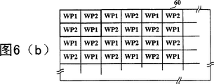
图6(a)至6(c)显示应用本实用新型的彩色显示装置之示意图。6(a) to 6(c) show schematic diagrams of a color display device applying the present invention.
具体实施方式Detailed ways
如前所述,现有技术对于在二元显示装置上产生多重明暗层次图像皆存在有各种缺点。然而,依据本实用新型的显示控制器除了有效地产生多重明暗层次图像于二元显示装置上以外,还提供了下列优点:(1)简单的电路组态、(2)容易实施的控制算法、(3)视觉干扰(例如闪烁或条纹)之避免、(4)信息量的充分利用、以及(5)数字图像信号的处理速度的提升。因而,依据本实用新型的显示控制器利用容易实施的控制算法控制二元显示装置,在不损失信息量的情况下,达到均匀而无条纹的多重明暗层次,并根据人眼感知的特性直接避免了闪烁的现象。As mentioned above, there are various shortcomings in the prior art for generating images with multiple light and dark levels on a binary display device. However, the display controller according to the present invention provides the following advantages in addition to effectively producing multiple light and dark gradation images on the binary display device: (1) simple circuit configuration, (2) easy-to-implement control algorithm, (3) Avoidance of visual disturbances such as flicker or stripes, (4) Full utilization of information volume, and (5) Improvement of processing speed of digital image signals. Therefore, according to the display controller of the present invention, the binary display device is controlled by an easy-to-implement control algorithm to achieve uniform and streak-free multiple light and shade levels without loss of information, and directly avoid flicker phenomenon.
下文中的说明与附图将使本实用新型的前述与其它目的、特征、与优点更明显。这里将参照附图详细说明依据本实用新型的较佳实施例。The following description and accompanying drawings will make the aforementioned and other objects, features and advantages of the present invention more apparent. Here, the preferred embodiments according to the present utility model will be described in detail with reference to the accompanying drawings.
参照图1,一个二元显示装置10由240×160个二元状态像素所组成,这些像素排列成具有240行与160列的阵列。请注意,虽然图1所示的二元显示装置10的尺寸为240×160,但本实用新型不限于此例子,而是可应用于具有任意尺寸的二元显示装置。为了在二元显示装置10上产生多重明暗层次图像,可将一幅具有多重明暗层次的图像分割成在时间上等间隔地显示的多个帧(Frame),其中每一帧的显示可按照特定的空间图案分别设定二元显示装置中的多个像素在二元状态ON/OFF中之一而实现。结果,在人眼视觉的时间/空间整合(integration)效应作用下,可有效地从二元显示装置上感知到多重明暗层次图像。Referring to FIG. 1 , a
假设在二元显示装置10上操作来显示一系列具有2n阶明暗层次的图像(n为正整数)。如图2所示,每一幅2n阶明暗层次图像由2n个帧所组成,其中相邻帧间隔着一固定的帧周期。在构成前一幅2n阶明暗层次图像的第2n帧显示后经过该固定的帧周期,下一幅2n阶明暗层次图像的第1帧即显示出。换言之,二元显示装置10上被操作成以一固定的帧速率显示帧,其中每2n个帧的组合可使人眼感知到一幅具有2n阶明暗层次的图像。具体而言,为了利用人眼视觉的时间整合效应,帧速率必须具有一相当大的值。原则上,愈大的帧速率,愈有益于人眼视觉之时间整合效应的利用,进而产生高品质的多重明暗层次图像。现有技术所采用的帧速率大约为50至120Hz,当n≤2时或许尚能在不引起闪烁的情况下显示出良好的2n阶明暗层次图像。然而,当n≥3时,现有技术则必须采用复杂的控制算法或抖动矩阵以弥补帧速率过低的缺陷,否则将无法避免闪烁。Assume that the
在依据本实用新型的一较佳实施例中,帧速率设定成大于或等于(2n×15)Hz。在此条件下,因为每一幅2n阶明暗层次图像具有2n个帧,所以相邻两幅2n阶明暗层次图像中的具有相同帧序号的任两帧的显示速率大于或等于15Hz(亦即每2n个帧周期出现一次)。在依据本实用新型的其它实施例中,较佳的帧速率亦可经由计算机仿真或实际测试而确定,只要帧速率足够高而能够避免人眼感知到闪烁现象即可。In a preferred embodiment according to the present invention, the frame rate is set to be greater than or equal to (2 n ×15) Hz. Under this condition, since each 2n -order light-and-dark layer image has 2n frames, the display rate of any two frames with the same frame number in two adjacent 2n- order light-dark layer images is greater than or equal to 15Hz ( That is, it occurs once every 2 n frame periods). In other embodiments according to the present invention, the preferred frame rate can also be determined through computer simulation or actual test, as long as the frame rate is high enough to avoid the flicker phenomenon perceived by human eyes.
为了利用人眼视觉的空间整合效应,依据本实用新型的显示控制器对于二元显示装置10的各个像素以垂直与水平皆交替的方式提供两组不同的波形图案信号。具体而言,如图3(a)所示,一基本的2×2像素单元30包括四个像素,其中位于一条对角线上的两个像素用以接收第一组波形图案信号WP1而位于另一条对角线上的两个像素则用以接收第二组波形图案信号WP2。在本实用新型中,第二组波形图案信号WP2被设计成不同于第一组波形图案信号WP1,随后将详细说明。回头参照图1,二元显示装置10可视为由多个图3(a)所示的基本的2×2像素单元30所组成。结果,标记有符号I的像素代表着用以接收第一组波形图案信号WP1的像素,而无标记的空白像素则代表着用以接收第二组波形图案信号WP2的像素。因此,二元显示装置10上的相邻的两个像素,不论是垂直相邻或水平相邻,接收着不相同的两组波形图案信号WP1与WP2。In order to take advantage of the spatial integration effect of human vision, the display controller according to the present invention provides two sets of different waveform pattern signals to each pixel of the
图3(b)显示二元显示装置10中任一个2×2像素阵列在一帧中的若干可能的空间图案A至H的示意图。在图3(b)中,标记有空心圆圈的像素代表着其处于二元状态中的ON状态(或称亮状态),而标记有实心圆圈的像素则代表着其处于二元状态中的OFF状态(或称暗状态)。在本实用新型中,分别提供至二元显示装置10的相邻的两个像素的不相同的两组波形图案信号WP1与WP2被设定成使该相邻的两个像素在2n个帧的至少一帧中处于彼此不同的操作状态,例如图3(b)中的空间图案A或B。换言之,相邻的两个像素的操作状态在空间上发生交错的效果。结果,在人眼视觉的空间整合作用下可感知到二元状态像素的切换速率增加了一倍。通过该方式,在前述帧速率被设定成大于或等于(2n×15)Hz的较佳实施例中,即使二元显示装置10中存在有一像素在2n个帧中仅切换一次,人眼所感知到的切换速率仍大于或等于30Hz。因此依据本实用新型的显示控制器更确实地避免闪烁与条纹的产生。FIG. 3( b ) shows a schematic diagram of several possible spatial patterns A to H in one frame of any 2×2 pixel array in the
图4(a)与4(b)显示由依据本实用新型的显示控制器所提供的两组波形图案信号WP1与WP2的一例子的时序图。图4(a)与4(b)所提供的两组波形图案信号WP1与WP2皆延伸了32个帧,因此可用来显示具有25(=32)阶明暗层次的图像。在图4(a)与4(b)中,第m阶波形图案信号被设计成在32个帧中的m个帧中具有脉冲而在其余(32-m)个帧中不具有脉冲。就相对应的第m阶波形图案信号而言,虽然第一与第二组波形图案信号WP1与WP2皆分别具有m个脉冲,但两者不同之处在于脉冲在全部32帧周期中的分布状态。如前所述,波形图案信号WP1与WP2被设定成使相邻的两个像素在2n个帧的至少一帧中处于彼此不同的操作状态。借着这种不同脉冲分布的设计,可利用人眼视觉的时间/空间整合效应而达成使像素切换速率倍增的感知效果。图4(a)与4(b)所示的波形图案信号WP1与WP2中的每一信号亦得考虑成一数字位序列(digital bit sequence)或由其所实施。举例而言,第一组波形图案信号的第22阶信号即为[11111001111001111100111100111100],其中位1代表有脉冲而位0则代表无脉冲。每一位是用在该多个连续帧中的一对应的帧中显示。由于每一位具有二元状态,故相当适合用来控制二元状态像素的操作。4(a) and 4(b) show a timing diagram of an example of two sets of waveform pattern signals WP1 and WP2 provided by the display controller according to the present invention. The two sets of waveform pattern signals WP1 and WP2 provided in FIGS. 4( a ) and 4 ( b ) are extended for 32 frames, so they can be used to display images with 2 5 (=32) levels of light and dark levels. In FIGS. 4(a) and 4(b), the m-th order waveform pattern signal is designed to have pulses in m frames out of 32 frames and not have pulses in the remaining (32-m) frames. As far as the corresponding m-th order waveform pattern signal is concerned, although the first and second sets of waveform pattern signals WP1 and WP2 both have m pulses respectively, the difference between them lies in the distribution of the pulses in the entire 32 frame period . As mentioned above, the waveform pattern signals WP1 and WP2 are set such that two adjacent pixels are in different operating states from each other in at least one frame of 2 n frames. With the design of different pulse distributions, the time/space integration effect of human vision can be utilized to achieve the perception effect of doubling the pixel switching rate. Each of the waveform pattern signals WP1 and WP2 shown in FIGS. 4(a) and 4(b) may also be considered as or implemented by a digital bit sequence. For example, the 22nd level signal of the first group of waveform pattern signals is [11111001111001111100111100111100], wherein
请注意,在图4(a)与4(b)中仅显示第一与第二组波形图案信号WP1与WP2中的第16阶至第32阶信号,因为在此实施例中第1至15阶信号被设计为第31至17阶信号的补码(complement)或反相信号,所以省略其图式。在依据本实用新型的另一实施例中,第1阶信号亦可设计成在全部32帧周期中皆不具有脉冲。Please note that only the 16th to 32nd order signals in the first and second groups of waveform pattern signals WP1 and WP2 are shown in FIGS. 4(a) and 4(b), because the 1st to 15th order signals are The order signals are designed as complements or inversion signals of the 31st to 17th order signals, so their illustrations are omitted. In another embodiment according to the present invention, the first-order signal can also be designed to have no pulse in all 32 frame periods.
虽然在前述实施例中图4(a)与4(b)所示的两组波形图案信号WP1与WP2用以显示32阶明暗层次图像,但本实用新型不限于此例子而可应用于从两组波形图案信号WP1与WP2的每一组中分别选出相对应的16个波形图案信号,用以显示16阶明暗层次图像。同理,本实用新型亦可应用于从两组波形图案信号WP1与WP2的每一组中分别选出相对应的8个波形图案信号,用以显示8阶明暗层次图像。Although the two groups of waveform pattern signals WP1 and WP2 shown in Figures 4(a) and 4(b) are used to display images with 32 levels of light and shade levels in the foregoing embodiment, the utility model is not limited to this example and can be applied from two Corresponding 16 waveform pattern signals are selected from each group of the waveform pattern signals WP1 and WP2 to display 16-level light and dark level images. Similarly, the present invention can also be applied to select 8 corresponding waveform pattern signals from each of the two groups of waveform pattern signals WP1 and WP2 to display 8-level light and dark layered images.
这里将参照图5(a)与5(b)说明在显示装置50上产生多重明暗层次图像的依据本实用新型的显示控制器51的电路组态及其操作。参照图5(a),本发明的显示控制器51包括有像素计数器53、扫描线计数器54、图像存储器52、波形图案选择器57和波形图案存储器56。其中像素计数器53和扫描线计数器54的输出端均连接至图像存储器52和波形图案选择器57的输入端;波形图案选择器57和图像存储器52的输出端均连接至波形图案存储器56的输入端;波形图案存储器56的输出端连接至显示装置50的输入端。图像存储器52储存有明暗层次资料,该明暗层次资料指示构成显示装置50的二元像素阵列中每一像素的明暗层次色阶。图像存储器52由像素计数器53所输出的行数目信号CN以及由扫描线计数器54所输出的列数目信号RN定出欲存取的地址。像素计数器53与扫描线计数器54分别使用像素时钟PCK与扫描线时钟SLCK作为时钟信号。响应于行数目信号CN与列数目信号RN,图像存储器52输出将显示于由行数目信号CN与列数目信号RN所寻址的像素上的明暗层次数据GD。虽然明暗层次数据GD可直接输入波形图案存储器56,但在依据本实用新型的一较佳实施例中,明暗层次数据GD经由查找表(Look Up Table)55而输入波形图案存储器56。查找表55的功用通常包括增加明暗层次资料GD的位数目、对明暗层次资料GD进行伽马(Gamma)修正、或其它类似的演算,借以增强将要显示的图像之品质。转换后明暗层次数据GD’从查找表55输入至波形图案存储器56。波形图案存储器56储存预定数目的数字位序列,其对应于依据本实用新型的波形图案信号,例如图4(a)与4(b)所示的波形图案信号。Here, the circuit configuration and operation of the
另一方面,波形图案选择器57基于所接收的用以确定像素地址的行数目信号CN与列数目信号RN,按照依据本实用新型的图3(a)所示的波形图案信号分配方法而输出波形图案选择信号WS至波形图案存储器56,用以确定使用第一组或第二组波形图案信号。同时,帧计数器58在帧时钟FCK的操作下输出帧数目信号FN至波形图案存储器56。响应于转换后明暗层次数据GD’、波形图案选择信号WS、以及帧数目信号FN,波形图案存储器56以一次一位的方式依序输出波形图案信号位WPB至二元显示装置50,借以产生多重明暗层次图像。在一实施例中,波形图案存储器56可储存有两组波形图案信号,且基于波形图案选择信号WS确定使用哪一组波形图案信号。在另一实施例中,波形图案存储器56可仅储存有单一组波形图案信号,且基于波形图案选择信号WS确定直接使用该组波形图案信号或从该组波形图案信号推导出另一组波形图案信号。举例而言,另一组波形图案信号可通过利用相位偏移的方式从所储存的该组波形图案信号推导出。广义而言,在依据本实用新型的显示控制器中,波形图案存储器56可通过各种合理技术或算法压缩或简化所需储存的信息,只要其能有效地基于转换后明暗层次数据GD’、波形图案选择信号WS、以及帧数目信号FN而正确地输出所期望的波形图案信号位WPB即可。On the other hand, the
图5(b)显示图5(a)的部分电路图,用以说明依据本实用新型的波形图案选择器57的一例子。参照图5(b),因为在本实用新型中仅使用两组波形图案信号且按照图3(a)所示的基本的2×2像素单元进行波形图案信号空间分配,所以波形图案选择器57可相当简单地仅由一异-或(Exclusive-OR)逻辑电路所实施。具体而言,互斥-或逻辑电路接收从像素计数器53所输出的行数目信号CN的最小有效位CNLSB以及从扫描线计数器54所输出的列数目信号RN的最小有效位RNLSB。参照互斥或逻辑运算的真值表可知,当两输入逻辑值相同时,输出逻辑值为0,而当两输入逻辑值不同时,输出逻辑值为1。因此,互斥或逻辑电路可有效地区分出图3(a)所示的基本的2×2像素单元中分别位于两对角线上的两对像素。FIG. 5( b ) shows a partial circuit diagram of FIG. 5( a ) to illustrate an example of the
综上所述,依据本实用新型的显示控制器仅使用两组波形图案信号即可在二元显示装置上产生具有2n明暗层次的图像。相较于使用非常多组相位偏移信号与精心设计的空间分布图案或者使用复杂且大尺寸的抖动矩阵的各种现有技术而言,依据本实用新型的显示控制器可大大地降低波形图案存储器56的记忆容量且使用构造简单的波形图案选择器57取代现有技术的空间分布图案存储器或抖动矩阵缓存器,进而大大提升数字图像信号的处理速度。In summary, the display controller according to the present invention can generate an image with 2 n light and dark levels on a binary display device by only using two sets of waveform pattern signals. The display controller according to the present invention can greatly reduce the waveform pattern The memory capacity of the
这里将参照图6(a)至6(c)说明依据本实用新型的显示控制器应用于彩色显示装置60上的例子。参照图6(a),彩色显示装置60由多个像素所构成的阵列所形成,其中每一像素分别用以显示红色(R)、绿色(G)、与蓝色(B)等三原色中的一色。在彩色显示装置60中,典型地,将一个红色像素(例如R11)、一个绿色像素(例如G11)、与一个蓝色像素(例如B11)排列在一起形成一彩色像素组61,用以组合出所期望的色彩。虽然图6(a)仅显示一种彩色显示装置的三原色像素排列方式,但本实用新型不限于此例子而可应用到由各式各样的三原色像素色排列方式所组成的彩色显示装置。Here, an example in which the display controller according to the present invention is applied to a
图6(b)显示依据本实用新型的显示控制器分配两组波形图案信号到彩色显示装置60的第一方式。在第一方式中,彩色显示装置60的每一个像素皆被视为最小分配单位,不论其颜色为何。因此,彩色显示装置60的像素按照图3(a)的基本的2×2像素单元30加以区分,藉而垂直上与水平上皆交替地接收两组波形图案信号WP1与WP2。FIG. 6( b ) shows a first way for the display controller to distribute two sets of waveform pattern signals to the
图6(c)显示依据本实用新型的显示控制器分配两组波形图案信号到彩色显示装置60的第二方式。在第二方式中,彩色显示装置60的由红色像素、绿色像素、与蓝色像素所构成的彩色像素组61被视为最小分配单位。倘若将图3(a)的基本的2×2像素单元30中的四个像素推广为四个作为最小分配单位的彩色像素组61,便可很轻易地按照图3(a)的基本的2×2像素单元30确定彩色显示装置60的各像素应该接收哪一组波形图案信号。在此情况下,彩色显示装置60的彩色像素组61垂直上与水平上皆交替地接收两组波形图案信号WP1与WP2。FIG. 6( c ) shows a second way for the display controller to distribute two sets of waveform pattern signals to the
虽然本实用新型已通过较佳实施例作为例示加以说明,但应了解的是:本实用新型不限于该被揭露的实施例。相反地,本实用新型意欲涵盖对于本领域的技术人员而言是明显的各种修改与相似配置。因此,权利要求的范围应根据最广的诠释,以包容所有此类修改与相似配置。Although the present invention has been described by means of preferred embodiments, it should be understood that the present invention is not limited to the disclosed embodiments. On the contrary, the invention is intended to cover various modifications and similar arrangements apparent to those skilled in the art. Accordingly, the scope of the claims should be accorded the broadest interpretation to embrace all such modifications and similar arrangements.
Claims (5)
Priority Applications (1)
| Application Number | Priority Date | Filing Date | Title |
|---|---|---|---|
| CN 200320130438 CN200947341Y (en) | 2003-12-22 | 2003-12-22 | Display controller for generating multiple shaded images |
Applications Claiming Priority (1)
| Application Number | Priority Date | Filing Date | Title |
|---|---|---|---|
| CN 200320130438 CN200947341Y (en) | 2003-12-22 | 2003-12-22 | Display controller for generating multiple shaded images |
Publications (1)
| Publication Number | Publication Date |
|---|---|
| CN200947341Y true CN200947341Y (en) | 2007-09-12 |
Family
ID=38734406
Family Applications (1)
| Application Number | Title | Priority Date | Filing Date |
|---|---|---|---|
| CN 200320130438 Expired - Fee Related CN200947341Y (en) | 2003-12-22 | 2003-12-22 | Display controller for generating multiple shaded images |
Country Status (1)
| Country | Link |
|---|---|
| CN (1) | CN200947341Y (en) |
Cited By (2)
| Publication number | Priority date | Publication date | Assignee | Title |
|---|---|---|---|---|
| US8970637B2 (en) | 2008-12-01 | 2015-03-03 | Lg Display Co., Ltd. | Unit and method of controlling frame rate and liquid crystal display device using the same |
| CN101751845B (en) * | 2008-12-01 | 2016-12-14 | 乐金显示有限公司 | Control the unit of frame per second and method and with this unit and the liquid crystal display of method |
-
2003
- 2003-12-22 CN CN 200320130438 patent/CN200947341Y/en not_active Expired - Fee Related
Cited By (2)
| Publication number | Priority date | Publication date | Assignee | Title |
|---|---|---|---|---|
| US8970637B2 (en) | 2008-12-01 | 2015-03-03 | Lg Display Co., Ltd. | Unit and method of controlling frame rate and liquid crystal display device using the same |
| CN101751845B (en) * | 2008-12-01 | 2016-12-14 | 乐金显示有限公司 | Control the unit of frame per second and method and with this unit and the liquid crystal display of method |
Similar Documents
| Publication | Publication Date | Title |
|---|---|---|
| US11295657B2 (en) | Method and system for switched display of grayscale of multi-line scan led | |
| CN100390854C (en) | Liquid crystal intermediate grayscale display method and liquid crystal display device using the method | |
| KR100653751B1 (en) | Driving method of display panel, driving circuit of display panel, and liquid crystal display device | |
| US9024964B2 (en) | System and method for dithering video data | |
| US6518977B1 (en) | Color image display apparatus and method | |
| US5068649A (en) | Method and apparatus for displaying different shades of gray on a liquid crystal display | |
| US8373727B2 (en) | Display apparatus and display panel driver including subtractive color processing circuit for error diffusion processing and weighting processing | |
| US6836232B2 (en) | Apparatus and method for gamma correction in a liquid crystal display | |
| US6239781B1 (en) | Gray-scale signal generating circuit and liquid crystal display | |
| US20030184508A1 (en) | Liquid crystal display and driving method thereof | |
| KR19980033102A (en) | Gradation display system | |
| JP7007789B2 (en) | Display panel driver and display panel drive method | |
| KR20030078786A (en) | Image display method and image display device | |
| KR930001649B1 (en) | Liquid crystal display | |
| KR100633812B1 (en) | Light modulation device | |
| US7319449B2 (en) | Image display apparatus and image display method | |
| CN1432987A (en) | Gamma correction device and method for liquid crystal display | |
| US6788306B2 (en) | Display apparatus displaying pseudo gray levels and method for displaying the same | |
| US20080042964A1 (en) | Simple-matrix liquid crystal driving method, liquid crystal driver, and liquid crystal display apparatus | |
| CN200947341Y (en) | Display controller for generating multiple shaded images | |
| US8947475B2 (en) | Spatially multiplexed pulse width modulation | |
| US7209151B2 (en) | Display controller for producing multi-gradation images | |
| US20060066592A1 (en) | Line scanning in a display | |
| US6081252A (en) | Dispersion-based technique for performing spacial dithering for a digital display system | |
| US20030085861A1 (en) | Gray scale driving method of liquid crystal display panel |
Legal Events
| Date | Code | Title | Description |
|---|---|---|---|
| C14 | Grant of patent or utility model | ||
| GR01 | Patent grant | ||
| C19 | Lapse of patent right due to non-payment of the annual fee | ||
| CF01 | Termination of patent right due to non-payment of annual fee |