CN1925817A - Hybrid intervertebral disc system - Google Patents
Hybrid intervertebral disc system Download PDFInfo
- Publication number
- CN1925817A CN1925817A CNA2005800065791A CN200580006579A CN1925817A CN 1925817 A CN1925817 A CN 1925817A CN A2005800065791 A CNA2005800065791 A CN A2005800065791A CN 200580006579 A CN200580006579 A CN 200580006579A CN 1925817 A CN1925817 A CN 1925817A
- Authority
- CN
- China
- Prior art keywords
- vertebral implant
- vertebral
- endplate
- core member
- flexible core
- Prior art date
- Legal status (The legal status is an assumption and is not a legal conclusion. Google has not performed a legal analysis and makes no representation as to the accuracy of the status listed.)
- Pending
Links
- LCBBKIIULOMJBX-UHFFFAOYSA-N C(C1)C=C2C1=C2 Chemical compound C(C1)C=C2C1=C2 LCBBKIIULOMJBX-UHFFFAOYSA-N 0.000 description 1
Images


Classifications
-
- A—HUMAN NECESSITIES
- A61—MEDICAL OR VETERINARY SCIENCE; HYGIENE
- A61F—FILTERS IMPLANTABLE INTO BLOOD VESSELS; PROSTHESES; DEVICES PROVIDING PATENCY TO, OR PREVENTING COLLAPSING OF, TUBULAR STRUCTURES OF THE BODY, e.g. STENTS; ORTHOPAEDIC, NURSING OR CONTRACEPTIVE DEVICES; FOMENTATION; TREATMENT OR PROTECTION OF EYES OR EARS; BANDAGES, DRESSINGS OR ABSORBENT PADS; FIRST-AID KITS
- A61F2/00—Filters implantable into blood vessels; Prostheses, i.e. artificial substitutes or replacements for parts of the body; Appliances for connecting them with the body; Devices providing patency to, or preventing collapsing of, tubular structures of the body, e.g. stents
- A61F2/02—Prostheses implantable into the body
- A61F2/30—Joints
- A61F2/44—Joints for the spine, e.g. vertebrae, spinal discs
- A61F2/442—Intervertebral or spinal discs, e.g. resilient
- A61F2/4425—Intervertebral or spinal discs, e.g. resilient made of articulated components
-
- A—HUMAN NECESSITIES
- A61—MEDICAL OR VETERINARY SCIENCE; HYGIENE
- A61F—FILTERS IMPLANTABLE INTO BLOOD VESSELS; PROSTHESES; DEVICES PROVIDING PATENCY TO, OR PREVENTING COLLAPSING OF, TUBULAR STRUCTURES OF THE BODY, e.g. STENTS; ORTHOPAEDIC, NURSING OR CONTRACEPTIVE DEVICES; FOMENTATION; TREATMENT OR PROTECTION OF EYES OR EARS; BANDAGES, DRESSINGS OR ABSORBENT PADS; FIRST-AID KITS
- A61F2/00—Filters implantable into blood vessels; Prostheses, i.e. artificial substitutes or replacements for parts of the body; Appliances for connecting them with the body; Devices providing patency to, or preventing collapsing of, tubular structures of the body, e.g. stents
- A61F2/02—Prostheses implantable into the body
- A61F2/08—Muscles; Tendons; Ligaments
-
- A—HUMAN NECESSITIES
- A61—MEDICAL OR VETERINARY SCIENCE; HYGIENE
- A61F—FILTERS IMPLANTABLE INTO BLOOD VESSELS; PROSTHESES; DEVICES PROVIDING PATENCY TO, OR PREVENTING COLLAPSING OF, TUBULAR STRUCTURES OF THE BODY, e.g. STENTS; ORTHOPAEDIC, NURSING OR CONTRACEPTIVE DEVICES; FOMENTATION; TREATMENT OR PROTECTION OF EYES OR EARS; BANDAGES, DRESSINGS OR ABSORBENT PADS; FIRST-AID KITS
- A61F2/00—Filters implantable into blood vessels; Prostheses, i.e. artificial substitutes or replacements for parts of the body; Appliances for connecting them with the body; Devices providing patency to, or preventing collapsing of, tubular structures of the body, e.g. stents
- A61F2/02—Prostheses implantable into the body
- A61F2/30—Joints
- A61F2002/30001—Additional features of subject-matter classified in A61F2/28, A61F2/30 and subgroups thereof
- A61F2002/30003—Material related properties of the prosthesis or of a coating on the prosthesis
- A61F2002/30004—Material related properties of the prosthesis or of a coating on the prosthesis the prosthesis being made from materials having different values of a given property at different locations within the same prosthesis
- A61F2002/30014—Material related properties of the prosthesis or of a coating on the prosthesis the prosthesis being made from materials having different values of a given property at different locations within the same prosthesis differing in elasticity, stiffness or compressibility
-
- A—HUMAN NECESSITIES
- A61—MEDICAL OR VETERINARY SCIENCE; HYGIENE
- A61F—FILTERS IMPLANTABLE INTO BLOOD VESSELS; PROSTHESES; DEVICES PROVIDING PATENCY TO, OR PREVENTING COLLAPSING OF, TUBULAR STRUCTURES OF THE BODY, e.g. STENTS; ORTHOPAEDIC, NURSING OR CONTRACEPTIVE DEVICES; FOMENTATION; TREATMENT OR PROTECTION OF EYES OR EARS; BANDAGES, DRESSINGS OR ABSORBENT PADS; FIRST-AID KITS
- A61F2/00—Filters implantable into blood vessels; Prostheses, i.e. artificial substitutes or replacements for parts of the body; Appliances for connecting them with the body; Devices providing patency to, or preventing collapsing of, tubular structures of the body, e.g. stents
- A61F2/02—Prostheses implantable into the body
- A61F2/30—Joints
- A61F2002/30001—Additional features of subject-matter classified in A61F2/28, A61F2/30 and subgroups thereof
- A61F2002/30108—Shapes
- A61F2002/3011—Cross-sections or two-dimensional shapes
- A61F2002/30112—Rounded shapes, e.g. with rounded corners
- A61F2002/30113—Rounded shapes, e.g. with rounded corners circular
-
- A—HUMAN NECESSITIES
- A61—MEDICAL OR VETERINARY SCIENCE; HYGIENE
- A61F—FILTERS IMPLANTABLE INTO BLOOD VESSELS; PROSTHESES; DEVICES PROVIDING PATENCY TO, OR PREVENTING COLLAPSING OF, TUBULAR STRUCTURES OF THE BODY, e.g. STENTS; ORTHOPAEDIC, NURSING OR CONTRACEPTIVE DEVICES; FOMENTATION; TREATMENT OR PROTECTION OF EYES OR EARS; BANDAGES, DRESSINGS OR ABSORBENT PADS; FIRST-AID KITS
- A61F2/00—Filters implantable into blood vessels; Prostheses, i.e. artificial substitutes or replacements for parts of the body; Appliances for connecting them with the body; Devices providing patency to, or preventing collapsing of, tubular structures of the body, e.g. stents
- A61F2/02—Prostheses implantable into the body
- A61F2/30—Joints
- A61F2002/30001—Additional features of subject-matter classified in A61F2/28, A61F2/30 and subgroups thereof
- A61F2002/30108—Shapes
- A61F2002/3011—Cross-sections or two-dimensional shapes
- A61F2002/30112—Rounded shapes, e.g. with rounded corners
- A61F2002/30133—Rounded shapes, e.g. with rounded corners kidney-shaped or bean-shaped
-
- A—HUMAN NECESSITIES
- A61—MEDICAL OR VETERINARY SCIENCE; HYGIENE
- A61F—FILTERS IMPLANTABLE INTO BLOOD VESSELS; PROSTHESES; DEVICES PROVIDING PATENCY TO, OR PREVENTING COLLAPSING OF, TUBULAR STRUCTURES OF THE BODY, e.g. STENTS; ORTHOPAEDIC, NURSING OR CONTRACEPTIVE DEVICES; FOMENTATION; TREATMENT OR PROTECTION OF EYES OR EARS; BANDAGES, DRESSINGS OR ABSORBENT PADS; FIRST-AID KITS
- A61F2/00—Filters implantable into blood vessels; Prostheses, i.e. artificial substitutes or replacements for parts of the body; Appliances for connecting them with the body; Devices providing patency to, or preventing collapsing of, tubular structures of the body, e.g. stents
- A61F2/02—Prostheses implantable into the body
- A61F2/30—Joints
- A61F2002/30001—Additional features of subject-matter classified in A61F2/28, A61F2/30 and subgroups thereof
- A61F2002/30108—Shapes
- A61F2002/3011—Cross-sections or two-dimensional shapes
- A61F2002/30138—Convex polygonal shapes
- A61F2002/30153—Convex polygonal shapes rectangular
-
- A—HUMAN NECESSITIES
- A61—MEDICAL OR VETERINARY SCIENCE; HYGIENE
- A61F—FILTERS IMPLANTABLE INTO BLOOD VESSELS; PROSTHESES; DEVICES PROVIDING PATENCY TO, OR PREVENTING COLLAPSING OF, TUBULAR STRUCTURES OF THE BODY, e.g. STENTS; ORTHOPAEDIC, NURSING OR CONTRACEPTIVE DEVICES; FOMENTATION; TREATMENT OR PROTECTION OF EYES OR EARS; BANDAGES, DRESSINGS OR ABSORBENT PADS; FIRST-AID KITS
- A61F2/00—Filters implantable into blood vessels; Prostheses, i.e. artificial substitutes or replacements for parts of the body; Appliances for connecting them with the body; Devices providing patency to, or preventing collapsing of, tubular structures of the body, e.g. stents
- A61F2/02—Prostheses implantable into the body
- A61F2/30—Joints
- A61F2002/30001—Additional features of subject-matter classified in A61F2/28, A61F2/30 and subgroups thereof
- A61F2002/30108—Shapes
- A61F2002/30199—Three-dimensional shapes
- A61F2002/302—Three-dimensional shapes toroidal, e.g. rings
-
- A—HUMAN NECESSITIES
- A61—MEDICAL OR VETERINARY SCIENCE; HYGIENE
- A61F—FILTERS IMPLANTABLE INTO BLOOD VESSELS; PROSTHESES; DEVICES PROVIDING PATENCY TO, OR PREVENTING COLLAPSING OF, TUBULAR STRUCTURES OF THE BODY, e.g. STENTS; ORTHOPAEDIC, NURSING OR CONTRACEPTIVE DEVICES; FOMENTATION; TREATMENT OR PROTECTION OF EYES OR EARS; BANDAGES, DRESSINGS OR ABSORBENT PADS; FIRST-AID KITS
- A61F2/00—Filters implantable into blood vessels; Prostheses, i.e. artificial substitutes or replacements for parts of the body; Appliances for connecting them with the body; Devices providing patency to, or preventing collapsing of, tubular structures of the body, e.g. stents
- A61F2/02—Prostheses implantable into the body
- A61F2/30—Joints
- A61F2002/30001—Additional features of subject-matter classified in A61F2/28, A61F2/30 and subgroups thereof
- A61F2002/30316—The prosthesis having different structural features at different locations within the same prosthesis; Connections between prosthetic parts; Special structural features of bone or joint prostheses not otherwise provided for
- A61F2002/30329—Connections or couplings between prosthetic parts, e.g. between modular parts; Connecting elements
- A61F2002/30331—Connections or couplings between prosthetic parts, e.g. between modular parts; Connecting elements made by longitudinally pushing a protrusion into a complementarily-shaped recess, e.g. held by friction fit
- A61F2002/30362—Connections or couplings between prosthetic parts, e.g. between modular parts; Connecting elements made by longitudinally pushing a protrusion into a complementarily-shaped recess, e.g. held by friction fit with possibility of relative movement between the protrusion and the recess
- A61F2002/30364—Rotation about the common longitudinal axis
-
- A—HUMAN NECESSITIES
- A61—MEDICAL OR VETERINARY SCIENCE; HYGIENE
- A61F—FILTERS IMPLANTABLE INTO BLOOD VESSELS; PROSTHESES; DEVICES PROVIDING PATENCY TO, OR PREVENTING COLLAPSING OF, TUBULAR STRUCTURES OF THE BODY, e.g. STENTS; ORTHOPAEDIC, NURSING OR CONTRACEPTIVE DEVICES; FOMENTATION; TREATMENT OR PROTECTION OF EYES OR EARS; BANDAGES, DRESSINGS OR ABSORBENT PADS; FIRST-AID KITS
- A61F2/00—Filters implantable into blood vessels; Prostheses, i.e. artificial substitutes or replacements for parts of the body; Appliances for connecting them with the body; Devices providing patency to, or preventing collapsing of, tubular structures of the body, e.g. stents
- A61F2/02—Prostheses implantable into the body
- A61F2/30—Joints
- A61F2002/30001—Additional features of subject-matter classified in A61F2/28, A61F2/30 and subgroups thereof
- A61F2002/30316—The prosthesis having different structural features at different locations within the same prosthesis; Connections between prosthetic parts; Special structural features of bone or joint prostheses not otherwise provided for
- A61F2002/30329—Connections or couplings between prosthetic parts, e.g. between modular parts; Connecting elements
- A61F2002/30331—Connections or couplings between prosthetic parts, e.g. between modular parts; Connecting elements made by longitudinally pushing a protrusion into a complementarily-shaped recess, e.g. held by friction fit
- A61F2002/30362—Connections or couplings between prosthetic parts, e.g. between modular parts; Connecting elements made by longitudinally pushing a protrusion into a complementarily-shaped recess, e.g. held by friction fit with possibility of relative movement between the protrusion and the recess
- A61F2002/30369—Limited lateral translation of the protrusion within a larger recess
-
- A—HUMAN NECESSITIES
- A61—MEDICAL OR VETERINARY SCIENCE; HYGIENE
- A61F—FILTERS IMPLANTABLE INTO BLOOD VESSELS; PROSTHESES; DEVICES PROVIDING PATENCY TO, OR PREVENTING COLLAPSING OF, TUBULAR STRUCTURES OF THE BODY, e.g. STENTS; ORTHOPAEDIC, NURSING OR CONTRACEPTIVE DEVICES; FOMENTATION; TREATMENT OR PROTECTION OF EYES OR EARS; BANDAGES, DRESSINGS OR ABSORBENT PADS; FIRST-AID KITS
- A61F2/00—Filters implantable into blood vessels; Prostheses, i.e. artificial substitutes or replacements for parts of the body; Appliances for connecting them with the body; Devices providing patency to, or preventing collapsing of, tubular structures of the body, e.g. stents
- A61F2/02—Prostheses implantable into the body
- A61F2/30—Joints
- A61F2002/30001—Additional features of subject-matter classified in A61F2/28, A61F2/30 and subgroups thereof
- A61F2002/30316—The prosthesis having different structural features at different locations within the same prosthesis; Connections between prosthetic parts; Special structural features of bone or joint prostheses not otherwise provided for
- A61F2002/30329—Connections or couplings between prosthetic parts, e.g. between modular parts; Connecting elements
- A61F2002/30448—Connections or couplings between prosthetic parts, e.g. between modular parts; Connecting elements using adhesives
-
- A—HUMAN NECESSITIES
- A61—MEDICAL OR VETERINARY SCIENCE; HYGIENE
- A61F—FILTERS IMPLANTABLE INTO BLOOD VESSELS; PROSTHESES; DEVICES PROVIDING PATENCY TO, OR PREVENTING COLLAPSING OF, TUBULAR STRUCTURES OF THE BODY, e.g. STENTS; ORTHOPAEDIC, NURSING OR CONTRACEPTIVE DEVICES; FOMENTATION; TREATMENT OR PROTECTION OF EYES OR EARS; BANDAGES, DRESSINGS OR ABSORBENT PADS; FIRST-AID KITS
- A61F2/00—Filters implantable into blood vessels; Prostheses, i.e. artificial substitutes or replacements for parts of the body; Appliances for connecting them with the body; Devices providing patency to, or preventing collapsing of, tubular structures of the body, e.g. stents
- A61F2/02—Prostheses implantable into the body
- A61F2/30—Joints
- A61F2002/30001—Additional features of subject-matter classified in A61F2/28, A61F2/30 and subgroups thereof
- A61F2002/30316—The prosthesis having different structural features at different locations within the same prosthesis; Connections between prosthetic parts; Special structural features of bone or joint prostheses not otherwise provided for
- A61F2002/30329—Connections or couplings between prosthetic parts, e.g. between modular parts; Connecting elements
- A61F2002/30462—Connections or couplings between prosthetic parts, e.g. between modular parts; Connecting elements retained or tied with a rope, string, thread, wire or cable
-
- A—HUMAN NECESSITIES
- A61—MEDICAL OR VETERINARY SCIENCE; HYGIENE
- A61F—FILTERS IMPLANTABLE INTO BLOOD VESSELS; PROSTHESES; DEVICES PROVIDING PATENCY TO, OR PREVENTING COLLAPSING OF, TUBULAR STRUCTURES OF THE BODY, e.g. STENTS; ORTHOPAEDIC, NURSING OR CONTRACEPTIVE DEVICES; FOMENTATION; TREATMENT OR PROTECTION OF EYES OR EARS; BANDAGES, DRESSINGS OR ABSORBENT PADS; FIRST-AID KITS
- A61F2/00—Filters implantable into blood vessels; Prostheses, i.e. artificial substitutes or replacements for parts of the body; Appliances for connecting them with the body; Devices providing patency to, or preventing collapsing of, tubular structures of the body, e.g. stents
- A61F2/02—Prostheses implantable into the body
- A61F2/30—Joints
- A61F2002/30001—Additional features of subject-matter classified in A61F2/28, A61F2/30 and subgroups thereof
- A61F2002/30316—The prosthesis having different structural features at different locations within the same prosthesis; Connections between prosthetic parts; Special structural features of bone or joint prostheses not otherwise provided for
- A61F2002/30329—Connections or couplings between prosthetic parts, e.g. between modular parts; Connecting elements
- A61F2002/30476—Connections or couplings between prosthetic parts, e.g. between modular parts; Connecting elements locked by an additional locking mechanism
- A61F2002/305—Snap connection
-
- A—HUMAN NECESSITIES
- A61—MEDICAL OR VETERINARY SCIENCE; HYGIENE
- A61F—FILTERS IMPLANTABLE INTO BLOOD VESSELS; PROSTHESES; DEVICES PROVIDING PATENCY TO, OR PREVENTING COLLAPSING OF, TUBULAR STRUCTURES OF THE BODY, e.g. STENTS; ORTHOPAEDIC, NURSING OR CONTRACEPTIVE DEVICES; FOMENTATION; TREATMENT OR PROTECTION OF EYES OR EARS; BANDAGES, DRESSINGS OR ABSORBENT PADS; FIRST-AID KITS
- A61F2/00—Filters implantable into blood vessels; Prostheses, i.e. artificial substitutes or replacements for parts of the body; Appliances for connecting them with the body; Devices providing patency to, or preventing collapsing of, tubular structures of the body, e.g. stents
- A61F2/02—Prostheses implantable into the body
- A61F2/30—Joints
- A61F2002/30001—Additional features of subject-matter classified in A61F2/28, A61F2/30 and subgroups thereof
- A61F2002/30316—The prosthesis having different structural features at different locations within the same prosthesis; Connections between prosthetic parts; Special structural features of bone or joint prostheses not otherwise provided for
- A61F2002/30535—Special structural features of bone or joint prostheses not otherwise provided for
- A61F2002/30563—Special structural features of bone or joint prostheses not otherwise provided for having elastic means or damping means, different from springs, e.g. including an elastomeric core or shock absorbers
-
- A—HUMAN NECESSITIES
- A61—MEDICAL OR VETERINARY SCIENCE; HYGIENE
- A61F—FILTERS IMPLANTABLE INTO BLOOD VESSELS; PROSTHESES; DEVICES PROVIDING PATENCY TO, OR PREVENTING COLLAPSING OF, TUBULAR STRUCTURES OF THE BODY, e.g. STENTS; ORTHOPAEDIC, NURSING OR CONTRACEPTIVE DEVICES; FOMENTATION; TREATMENT OR PROTECTION OF EYES OR EARS; BANDAGES, DRESSINGS OR ABSORBENT PADS; FIRST-AID KITS
- A61F2/00—Filters implantable into blood vessels; Prostheses, i.e. artificial substitutes or replacements for parts of the body; Appliances for connecting them with the body; Devices providing patency to, or preventing collapsing of, tubular structures of the body, e.g. stents
- A61F2/02—Prostheses implantable into the body
- A61F2/30—Joints
- A61F2002/30001—Additional features of subject-matter classified in A61F2/28, A61F2/30 and subgroups thereof
- A61F2002/30316—The prosthesis having different structural features at different locations within the same prosthesis; Connections between prosthetic parts; Special structural features of bone or joint prostheses not otherwise provided for
- A61F2002/30535—Special structural features of bone or joint prostheses not otherwise provided for
- A61F2002/30581—Special structural features of bone or joint prostheses not otherwise provided for having a pocket filled with fluid, e.g. liquid
-
- A—HUMAN NECESSITIES
- A61—MEDICAL OR VETERINARY SCIENCE; HYGIENE
- A61F—FILTERS IMPLANTABLE INTO BLOOD VESSELS; PROSTHESES; DEVICES PROVIDING PATENCY TO, OR PREVENTING COLLAPSING OF, TUBULAR STRUCTURES OF THE BODY, e.g. STENTS; ORTHOPAEDIC, NURSING OR CONTRACEPTIVE DEVICES; FOMENTATION; TREATMENT OR PROTECTION OF EYES OR EARS; BANDAGES, DRESSINGS OR ABSORBENT PADS; FIRST-AID KITS
- A61F2/00—Filters implantable into blood vessels; Prostheses, i.e. artificial substitutes or replacements for parts of the body; Appliances for connecting them with the body; Devices providing patency to, or preventing collapsing of, tubular structures of the body, e.g. stents
- A61F2/02—Prostheses implantable into the body
- A61F2/30—Joints
- A61F2002/30001—Additional features of subject-matter classified in A61F2/28, A61F2/30 and subgroups thereof
- A61F2002/30621—Features concerning the anatomical functioning or articulation of the prosthetic joint
- A61F2002/30649—Ball-and-socket joints
- A61F2002/30662—Ball-and-socket joints with rotation-limiting means
-
- A—HUMAN NECESSITIES
- A61—MEDICAL OR VETERINARY SCIENCE; HYGIENE
- A61F—FILTERS IMPLANTABLE INTO BLOOD VESSELS; PROSTHESES; DEVICES PROVIDING PATENCY TO, OR PREVENTING COLLAPSING OF, TUBULAR STRUCTURES OF THE BODY, e.g. STENTS; ORTHOPAEDIC, NURSING OR CONTRACEPTIVE DEVICES; FOMENTATION; TREATMENT OR PROTECTION OF EYES OR EARS; BANDAGES, DRESSINGS OR ABSORBENT PADS; FIRST-AID KITS
- A61F2/00—Filters implantable into blood vessels; Prostheses, i.e. artificial substitutes or replacements for parts of the body; Appliances for connecting them with the body; Devices providing patency to, or preventing collapsing of, tubular structures of the body, e.g. stents
- A61F2/02—Prostheses implantable into the body
- A61F2/30—Joints
- A61F2002/30001—Additional features of subject-matter classified in A61F2/28, A61F2/30 and subgroups thereof
- A61F2002/30667—Features concerning an interaction with the environment or a particular use of the prosthesis
- A61F2002/30677—Means for introducing or releasing pharmaceutical products, e.g. antibiotics, into the body
-
- A—HUMAN NECESSITIES
- A61—MEDICAL OR VETERINARY SCIENCE; HYGIENE
- A61F—FILTERS IMPLANTABLE INTO BLOOD VESSELS; PROSTHESES; DEVICES PROVIDING PATENCY TO, OR PREVENTING COLLAPSING OF, TUBULAR STRUCTURES OF THE BODY, e.g. STENTS; ORTHOPAEDIC, NURSING OR CONTRACEPTIVE DEVICES; FOMENTATION; TREATMENT OR PROTECTION OF EYES OR EARS; BANDAGES, DRESSINGS OR ABSORBENT PADS; FIRST-AID KITS
- A61F2/00—Filters implantable into blood vessels; Prostheses, i.e. artificial substitutes or replacements for parts of the body; Appliances for connecting them with the body; Devices providing patency to, or preventing collapsing of, tubular structures of the body, e.g. stents
- A61F2/02—Prostheses implantable into the body
- A61F2/30—Joints
- A61F2/30767—Special external or bone-contacting surface, e.g. coating for improving bone ingrowth
- A61F2/30771—Special external or bone-contacting surface, e.g. coating for improving bone ingrowth applied in original prostheses, e.g. holes or grooves
- A61F2002/30841—Sharp anchoring protrusions for impaction into the bone, e.g. sharp pins, spikes
-
- A—HUMAN NECESSITIES
- A61—MEDICAL OR VETERINARY SCIENCE; HYGIENE
- A61F—FILTERS IMPLANTABLE INTO BLOOD VESSELS; PROSTHESES; DEVICES PROVIDING PATENCY TO, OR PREVENTING COLLAPSING OF, TUBULAR STRUCTURES OF THE BODY, e.g. STENTS; ORTHOPAEDIC, NURSING OR CONTRACEPTIVE DEVICES; FOMENTATION; TREATMENT OR PROTECTION OF EYES OR EARS; BANDAGES, DRESSINGS OR ABSORBENT PADS; FIRST-AID KITS
- A61F2/00—Filters implantable into blood vessels; Prostheses, i.e. artificial substitutes or replacements for parts of the body; Appliances for connecting them with the body; Devices providing patency to, or preventing collapsing of, tubular structures of the body, e.g. stents
- A61F2/02—Prostheses implantable into the body
- A61F2/30—Joints
- A61F2/30767—Special external or bone-contacting surface, e.g. coating for improving bone ingrowth
- A61F2/30771—Special external or bone-contacting surface, e.g. coating for improving bone ingrowth applied in original prostheses, e.g. holes or grooves
- A61F2002/30878—Special external or bone-contacting surface, e.g. coating for improving bone ingrowth applied in original prostheses, e.g. holes or grooves with non-sharp protrusions, for instance contacting the bone for anchoring, e.g. keels, pegs, pins, posts, shanks, stems, struts
-
- A—HUMAN NECESSITIES
- A61—MEDICAL OR VETERINARY SCIENCE; HYGIENE
- A61F—FILTERS IMPLANTABLE INTO BLOOD VESSELS; PROSTHESES; DEVICES PROVIDING PATENCY TO, OR PREVENTING COLLAPSING OF, TUBULAR STRUCTURES OF THE BODY, e.g. STENTS; ORTHOPAEDIC, NURSING OR CONTRACEPTIVE DEVICES; FOMENTATION; TREATMENT OR PROTECTION OF EYES OR EARS; BANDAGES, DRESSINGS OR ABSORBENT PADS; FIRST-AID KITS
- A61F2/00—Filters implantable into blood vessels; Prostheses, i.e. artificial substitutes or replacements for parts of the body; Appliances for connecting them with the body; Devices providing patency to, or preventing collapsing of, tubular structures of the body, e.g. stents
- A61F2/02—Prostheses implantable into the body
- A61F2/30—Joints
- A61F2/30767—Special external or bone-contacting surface, e.g. coating for improving bone ingrowth
- A61F2/30771—Special external or bone-contacting surface, e.g. coating for improving bone ingrowth applied in original prostheses, e.g. holes or grooves
- A61F2002/30904—Special external or bone-contacting surface, e.g. coating for improving bone ingrowth applied in original prostheses, e.g. holes or grooves serrated profile, i.e. saw-toothed
-
- A—HUMAN NECESSITIES
- A61—MEDICAL OR VETERINARY SCIENCE; HYGIENE
- A61F—FILTERS IMPLANTABLE INTO BLOOD VESSELS; PROSTHESES; DEVICES PROVIDING PATENCY TO, OR PREVENTING COLLAPSING OF, TUBULAR STRUCTURES OF THE BODY, e.g. STENTS; ORTHOPAEDIC, NURSING OR CONTRACEPTIVE DEVICES; FOMENTATION; TREATMENT OR PROTECTION OF EYES OR EARS; BANDAGES, DRESSINGS OR ABSORBENT PADS; FIRST-AID KITS
- A61F2/00—Filters implantable into blood vessels; Prostheses, i.e. artificial substitutes or replacements for parts of the body; Appliances for connecting them with the body; Devices providing patency to, or preventing collapsing of, tubular structures of the body, e.g. stents
- A61F2/02—Prostheses implantable into the body
- A61F2/30—Joints
- A61F2/30767—Special external or bone-contacting surface, e.g. coating for improving bone ingrowth
- A61F2002/30906—Special external or bone-contacting surface, e.g. coating for improving bone ingrowth shot- sand- or grit-blasted
-
- A—HUMAN NECESSITIES
- A61—MEDICAL OR VETERINARY SCIENCE; HYGIENE
- A61F—FILTERS IMPLANTABLE INTO BLOOD VESSELS; PROSTHESES; DEVICES PROVIDING PATENCY TO, OR PREVENTING COLLAPSING OF, TUBULAR STRUCTURES OF THE BODY, e.g. STENTS; ORTHOPAEDIC, NURSING OR CONTRACEPTIVE DEVICES; FOMENTATION; TREATMENT OR PROTECTION OF EYES OR EARS; BANDAGES, DRESSINGS OR ABSORBENT PADS; FIRST-AID KITS
- A61F2/00—Filters implantable into blood vessels; Prostheses, i.e. artificial substitutes or replacements for parts of the body; Appliances for connecting them with the body; Devices providing patency to, or preventing collapsing of, tubular structures of the body, e.g. stents
- A61F2/02—Prostheses implantable into the body
- A61F2/30—Joints
- A61F2/30767—Special external or bone-contacting surface, e.g. coating for improving bone ingrowth
- A61F2002/30925—Special external or bone-contacting surface, e.g. coating for improving bone ingrowth etched
-
- A—HUMAN NECESSITIES
- A61—MEDICAL OR VETERINARY SCIENCE; HYGIENE
- A61F—FILTERS IMPLANTABLE INTO BLOOD VESSELS; PROSTHESES; DEVICES PROVIDING PATENCY TO, OR PREVENTING COLLAPSING OF, TUBULAR STRUCTURES OF THE BODY, e.g. STENTS; ORTHOPAEDIC, NURSING OR CONTRACEPTIVE DEVICES; FOMENTATION; TREATMENT OR PROTECTION OF EYES OR EARS; BANDAGES, DRESSINGS OR ABSORBENT PADS; FIRST-AID KITS
- A61F2/00—Filters implantable into blood vessels; Prostheses, i.e. artificial substitutes or replacements for parts of the body; Appliances for connecting them with the body; Devices providing patency to, or preventing collapsing of, tubular structures of the body, e.g. stents
- A61F2/02—Prostheses implantable into the body
- A61F2/30—Joints
- A61F2/44—Joints for the spine, e.g. vertebrae, spinal discs
- A61F2/442—Intervertebral or spinal discs, e.g. resilient
- A61F2/4425—Intervertebral or spinal discs, e.g. resilient made of articulated components
- A61F2002/443—Intervertebral or spinal discs, e.g. resilient made of articulated components having two transversal endplates and at least one intermediate component
-
- A—HUMAN NECESSITIES
- A61—MEDICAL OR VETERINARY SCIENCE; HYGIENE
- A61F—FILTERS IMPLANTABLE INTO BLOOD VESSELS; PROSTHESES; DEVICES PROVIDING PATENCY TO, OR PREVENTING COLLAPSING OF, TUBULAR STRUCTURES OF THE BODY, e.g. STENTS; ORTHOPAEDIC, NURSING OR CONTRACEPTIVE DEVICES; FOMENTATION; TREATMENT OR PROTECTION OF EYES OR EARS; BANDAGES, DRESSINGS OR ABSORBENT PADS; FIRST-AID KITS
- A61F2220/00—Fixations or connections for prostheses classified in groups A61F2/00 - A61F2/26 or A61F2/82 or A61F9/00 or A61F11/00 or subgroups thereof
- A61F2220/0025—Connections or couplings between prosthetic parts, e.g. between modular parts; Connecting elements
- A61F2220/0033—Connections or couplings between prosthetic parts, e.g. between modular parts; Connecting elements made by longitudinally pushing a protrusion into a complementary-shaped recess, e.g. held by friction fit
-
- A—HUMAN NECESSITIES
- A61—MEDICAL OR VETERINARY SCIENCE; HYGIENE
- A61F—FILTERS IMPLANTABLE INTO BLOOD VESSELS; PROSTHESES; DEVICES PROVIDING PATENCY TO, OR PREVENTING COLLAPSING OF, TUBULAR STRUCTURES OF THE BODY, e.g. STENTS; ORTHOPAEDIC, NURSING OR CONTRACEPTIVE DEVICES; FOMENTATION; TREATMENT OR PROTECTION OF EYES OR EARS; BANDAGES, DRESSINGS OR ABSORBENT PADS; FIRST-AID KITS
- A61F2220/00—Fixations or connections for prostheses classified in groups A61F2/00 - A61F2/26 or A61F2/82 or A61F9/00 or A61F11/00 or subgroups thereof
- A61F2220/0025—Connections or couplings between prosthetic parts, e.g. between modular parts; Connecting elements
- A61F2220/005—Connections or couplings between prosthetic parts, e.g. between modular parts; Connecting elements using adhesives
-
- A—HUMAN NECESSITIES
- A61—MEDICAL OR VETERINARY SCIENCE; HYGIENE
- A61F—FILTERS IMPLANTABLE INTO BLOOD VESSELS; PROSTHESES; DEVICES PROVIDING PATENCY TO, OR PREVENTING COLLAPSING OF, TUBULAR STRUCTURES OF THE BODY, e.g. STENTS; ORTHOPAEDIC, NURSING OR CONTRACEPTIVE DEVICES; FOMENTATION; TREATMENT OR PROTECTION OF EYES OR EARS; BANDAGES, DRESSINGS OR ABSORBENT PADS; FIRST-AID KITS
- A61F2220/00—Fixations or connections for prostheses classified in groups A61F2/00 - A61F2/26 or A61F2/82 or A61F9/00 or A61F11/00 or subgroups thereof
- A61F2220/0025—Connections or couplings between prosthetic parts, e.g. between modular parts; Connecting elements
- A61F2220/0075—Connections or couplings between prosthetic parts, e.g. between modular parts; Connecting elements sutured, ligatured or stitched, retained or tied with a rope, string, thread, wire or cable
-
- A—HUMAN NECESSITIES
- A61—MEDICAL OR VETERINARY SCIENCE; HYGIENE
- A61F—FILTERS IMPLANTABLE INTO BLOOD VESSELS; PROSTHESES; DEVICES PROVIDING PATENCY TO, OR PREVENTING COLLAPSING OF, TUBULAR STRUCTURES OF THE BODY, e.g. STENTS; ORTHOPAEDIC, NURSING OR CONTRACEPTIVE DEVICES; FOMENTATION; TREATMENT OR PROTECTION OF EYES OR EARS; BANDAGES, DRESSINGS OR ABSORBENT PADS; FIRST-AID KITS
- A61F2230/00—Geometry of prostheses classified in groups A61F2/00 - A61F2/26 or A61F2/82 or A61F9/00 or A61F11/00 or subgroups thereof
- A61F2230/0002—Two-dimensional shapes, e.g. cross-sections
- A61F2230/0004—Rounded shapes, e.g. with rounded corners
- A61F2230/0006—Rounded shapes, e.g. with rounded corners circular
-
- A—HUMAN NECESSITIES
- A61—MEDICAL OR VETERINARY SCIENCE; HYGIENE
- A61F—FILTERS IMPLANTABLE INTO BLOOD VESSELS; PROSTHESES; DEVICES PROVIDING PATENCY TO, OR PREVENTING COLLAPSING OF, TUBULAR STRUCTURES OF THE BODY, e.g. STENTS; ORTHOPAEDIC, NURSING OR CONTRACEPTIVE DEVICES; FOMENTATION; TREATMENT OR PROTECTION OF EYES OR EARS; BANDAGES, DRESSINGS OR ABSORBENT PADS; FIRST-AID KITS
- A61F2230/00—Geometry of prostheses classified in groups A61F2/00 - A61F2/26 or A61F2/82 or A61F9/00 or A61F11/00 or subgroups thereof
- A61F2230/0002—Two-dimensional shapes, e.g. cross-sections
- A61F2230/0004—Rounded shapes, e.g. with rounded corners
- A61F2230/0015—Kidney-shaped, e.g. bean-shaped
-
- A—HUMAN NECESSITIES
- A61—MEDICAL OR VETERINARY SCIENCE; HYGIENE
- A61F—FILTERS IMPLANTABLE INTO BLOOD VESSELS; PROSTHESES; DEVICES PROVIDING PATENCY TO, OR PREVENTING COLLAPSING OF, TUBULAR STRUCTURES OF THE BODY, e.g. STENTS; ORTHOPAEDIC, NURSING OR CONTRACEPTIVE DEVICES; FOMENTATION; TREATMENT OR PROTECTION OF EYES OR EARS; BANDAGES, DRESSINGS OR ABSORBENT PADS; FIRST-AID KITS
- A61F2230/00—Geometry of prostheses classified in groups A61F2/00 - A61F2/26 or A61F2/82 or A61F9/00 or A61F11/00 or subgroups thereof
- A61F2230/0002—Two-dimensional shapes, e.g. cross-sections
- A61F2230/0017—Angular shapes
- A61F2230/0019—Angular shapes rectangular
-
- A—HUMAN NECESSITIES
- A61—MEDICAL OR VETERINARY SCIENCE; HYGIENE
- A61F—FILTERS IMPLANTABLE INTO BLOOD VESSELS; PROSTHESES; DEVICES PROVIDING PATENCY TO, OR PREVENTING COLLAPSING OF, TUBULAR STRUCTURES OF THE BODY, e.g. STENTS; ORTHOPAEDIC, NURSING OR CONTRACEPTIVE DEVICES; FOMENTATION; TREATMENT OR PROTECTION OF EYES OR EARS; BANDAGES, DRESSINGS OR ABSORBENT PADS; FIRST-AID KITS
- A61F2230/00—Geometry of prostheses classified in groups A61F2/00 - A61F2/26 or A61F2/82 or A61F9/00 or A61F11/00 or subgroups thereof
- A61F2230/0063—Three-dimensional shapes
- A61F2230/0065—Three-dimensional shapes toroidal, e.g. ring-shaped, doughnut-shaped
-
- A—HUMAN NECESSITIES
- A61—MEDICAL OR VETERINARY SCIENCE; HYGIENE
- A61F—FILTERS IMPLANTABLE INTO BLOOD VESSELS; PROSTHESES; DEVICES PROVIDING PATENCY TO, OR PREVENTING COLLAPSING OF, TUBULAR STRUCTURES OF THE BODY, e.g. STENTS; ORTHOPAEDIC, NURSING OR CONTRACEPTIVE DEVICES; FOMENTATION; TREATMENT OR PROTECTION OF EYES OR EARS; BANDAGES, DRESSINGS OR ABSORBENT PADS; FIRST-AID KITS
- A61F2250/00—Special features of prostheses classified in groups A61F2/00 - A61F2/26 or A61F2/82 or A61F9/00 or A61F11/00 or subgroups thereof
- A61F2250/0014—Special features of prostheses classified in groups A61F2/00 - A61F2/26 or A61F2/82 or A61F9/00 or A61F11/00 or subgroups thereof having different values of a given property or geometrical feature, e.g. mechanical property or material property, at different locations within the same prosthesis
- A61F2250/0018—Special features of prostheses classified in groups A61F2/00 - A61F2/26 or A61F2/82 or A61F9/00 or A61F11/00 or subgroups thereof having different values of a given property or geometrical feature, e.g. mechanical property or material property, at different locations within the same prosthesis differing in elasticity, stiffness or compressibility
-
- A—HUMAN NECESSITIES
- A61—MEDICAL OR VETERINARY SCIENCE; HYGIENE
- A61F—FILTERS IMPLANTABLE INTO BLOOD VESSELS; PROSTHESES; DEVICES PROVIDING PATENCY TO, OR PREVENTING COLLAPSING OF, TUBULAR STRUCTURES OF THE BODY, e.g. STENTS; ORTHOPAEDIC, NURSING OR CONTRACEPTIVE DEVICES; FOMENTATION; TREATMENT OR PROTECTION OF EYES OR EARS; BANDAGES, DRESSINGS OR ABSORBENT PADS; FIRST-AID KITS
- A61F2310/00—Prostheses classified in A61F2/28 or A61F2/30 - A61F2/44 being constructed from or coated with a particular material
- A61F2310/00005—The prosthesis being constructed from a particular material
- A61F2310/00011—Metals or alloys
- A61F2310/00017—Iron- or Fe-based alloys, e.g. stainless steel
-
- A—HUMAN NECESSITIES
- A61—MEDICAL OR VETERINARY SCIENCE; HYGIENE
- A61F—FILTERS IMPLANTABLE INTO BLOOD VESSELS; PROSTHESES; DEVICES PROVIDING PATENCY TO, OR PREVENTING COLLAPSING OF, TUBULAR STRUCTURES OF THE BODY, e.g. STENTS; ORTHOPAEDIC, NURSING OR CONTRACEPTIVE DEVICES; FOMENTATION; TREATMENT OR PROTECTION OF EYES OR EARS; BANDAGES, DRESSINGS OR ABSORBENT PADS; FIRST-AID KITS
- A61F2310/00—Prostheses classified in A61F2/28 or A61F2/30 - A61F2/44 being constructed from or coated with a particular material
- A61F2310/00005—The prosthesis being constructed from a particular material
- A61F2310/00011—Metals or alloys
- A61F2310/00023—Titanium or titanium-based alloys, e.g. Ti-Ni alloys
-
- A—HUMAN NECESSITIES
- A61—MEDICAL OR VETERINARY SCIENCE; HYGIENE
- A61F—FILTERS IMPLANTABLE INTO BLOOD VESSELS; PROSTHESES; DEVICES PROVIDING PATENCY TO, OR PREVENTING COLLAPSING OF, TUBULAR STRUCTURES OF THE BODY, e.g. STENTS; ORTHOPAEDIC, NURSING OR CONTRACEPTIVE DEVICES; FOMENTATION; TREATMENT OR PROTECTION OF EYES OR EARS; BANDAGES, DRESSINGS OR ABSORBENT PADS; FIRST-AID KITS
- A61F2310/00—Prostheses classified in A61F2/28 or A61F2/30 - A61F2/44 being constructed from or coated with a particular material
- A61F2310/00005—The prosthesis being constructed from a particular material
- A61F2310/00011—Metals or alloys
- A61F2310/00029—Cobalt-based alloys, e.g. Co-Cr alloys or Vitallium
-
- A—HUMAN NECESSITIES
- A61—MEDICAL OR VETERINARY SCIENCE; HYGIENE
- A61F—FILTERS IMPLANTABLE INTO BLOOD VESSELS; PROSTHESES; DEVICES PROVIDING PATENCY TO, OR PREVENTING COLLAPSING OF, TUBULAR STRUCTURES OF THE BODY, e.g. STENTS; ORTHOPAEDIC, NURSING OR CONTRACEPTIVE DEVICES; FOMENTATION; TREATMENT OR PROTECTION OF EYES OR EARS; BANDAGES, DRESSINGS OR ABSORBENT PADS; FIRST-AID KITS
- A61F2310/00—Prostheses classified in A61F2/28 or A61F2/30 - A61F2/44 being constructed from or coated with a particular material
- A61F2310/00005—The prosthesis being constructed from a particular material
- A61F2310/00161—Carbon; Graphite
- A61F2310/00167—Diamond or diamond-like carbon
-
- A—HUMAN NECESSITIES
- A61—MEDICAL OR VETERINARY SCIENCE; HYGIENE
- A61F—FILTERS IMPLANTABLE INTO BLOOD VESSELS; PROSTHESES; DEVICES PROVIDING PATENCY TO, OR PREVENTING COLLAPSING OF, TUBULAR STRUCTURES OF THE BODY, e.g. STENTS; ORTHOPAEDIC, NURSING OR CONTRACEPTIVE DEVICES; FOMENTATION; TREATMENT OR PROTECTION OF EYES OR EARS; BANDAGES, DRESSINGS OR ABSORBENT PADS; FIRST-AID KITS
- A61F2310/00—Prostheses classified in A61F2/28 or A61F2/30 - A61F2/44 being constructed from or coated with a particular material
- A61F2310/00005—The prosthesis being constructed from a particular material
- A61F2310/00179—Ceramics or ceramic-like structures
- A61F2310/00185—Ceramics or ceramic-like structures based on metal oxides
- A61F2310/00203—Ceramics or ceramic-like structures based on metal oxides containing alumina or aluminium oxide
-
- A—HUMAN NECESSITIES
- A61—MEDICAL OR VETERINARY SCIENCE; HYGIENE
- A61F—FILTERS IMPLANTABLE INTO BLOOD VESSELS; PROSTHESES; DEVICES PROVIDING PATENCY TO, OR PREVENTING COLLAPSING OF, TUBULAR STRUCTURES OF THE BODY, e.g. STENTS; ORTHOPAEDIC, NURSING OR CONTRACEPTIVE DEVICES; FOMENTATION; TREATMENT OR PROTECTION OF EYES OR EARS; BANDAGES, DRESSINGS OR ABSORBENT PADS; FIRST-AID KITS
- A61F2310/00—Prostheses classified in A61F2/28 or A61F2/30 - A61F2/44 being constructed from or coated with a particular material
- A61F2310/00005—The prosthesis being constructed from a particular material
- A61F2310/00179—Ceramics or ceramic-like structures
- A61F2310/00185—Ceramics or ceramic-like structures based on metal oxides
- A61F2310/00239—Ceramics or ceramic-like structures based on metal oxides containing zirconia or zirconium oxide ZrO2
-
- A—HUMAN NECESSITIES
- A61—MEDICAL OR VETERINARY SCIENCE; HYGIENE
- A61F—FILTERS IMPLANTABLE INTO BLOOD VESSELS; PROSTHESES; DEVICES PROVIDING PATENCY TO, OR PREVENTING COLLAPSING OF, TUBULAR STRUCTURES OF THE BODY, e.g. STENTS; ORTHOPAEDIC, NURSING OR CONTRACEPTIVE DEVICES; FOMENTATION; TREATMENT OR PROTECTION OF EYES OR EARS; BANDAGES, DRESSINGS OR ABSORBENT PADS; FIRST-AID KITS
- A61F2310/00—Prostheses classified in A61F2/28 or A61F2/30 - A61F2/44 being constructed from or coated with a particular material
- A61F2310/00389—The prosthesis being coated or covered with a particular material
- A61F2310/00574—Coating or prosthesis-covering structure made of carbon, e.g. of pyrocarbon
- A61F2310/0058—Coating made of diamond or of diamond-like carbon DLC
-
- A—HUMAN NECESSITIES
- A61—MEDICAL OR VETERINARY SCIENCE; HYGIENE
- A61F—FILTERS IMPLANTABLE INTO BLOOD VESSELS; PROSTHESES; DEVICES PROVIDING PATENCY TO, OR PREVENTING COLLAPSING OF, TUBULAR STRUCTURES OF THE BODY, e.g. STENTS; ORTHOPAEDIC, NURSING OR CONTRACEPTIVE DEVICES; FOMENTATION; TREATMENT OR PROTECTION OF EYES OR EARS; BANDAGES, DRESSINGS OR ABSORBENT PADS; FIRST-AID KITS
- A61F2310/00—Prostheses classified in A61F2/28 or A61F2/30 - A61F2/44 being constructed from or coated with a particular material
- A61F2310/00389—The prosthesis being coated or covered with a particular material
- A61F2310/00592—Coating or prosthesis-covering structure made of ceramics or of ceramic-like compounds
- A61F2310/00796—Coating or prosthesis-covering structure made of a phosphorus-containing compound, e.g. hydroxy(l)apatite
-
- A—HUMAN NECESSITIES
- A61—MEDICAL OR VETERINARY SCIENCE; HYGIENE
- A61F—FILTERS IMPLANTABLE INTO BLOOD VESSELS; PROSTHESES; DEVICES PROVIDING PATENCY TO, OR PREVENTING COLLAPSING OF, TUBULAR STRUCTURES OF THE BODY, e.g. STENTS; ORTHOPAEDIC, NURSING OR CONTRACEPTIVE DEVICES; FOMENTATION; TREATMENT OR PROTECTION OF EYES OR EARS; BANDAGES, DRESSINGS OR ABSORBENT PADS; FIRST-AID KITS
- A61F2310/00—Prostheses classified in A61F2/28 or A61F2/30 - A61F2/44 being constructed from or coated with a particular material
- A61F2310/00389—The prosthesis being coated or covered with a particular material
- A61F2310/00976—Coating or prosthesis-covering structure made of proteins or of polypeptides, e.g. of bone morphogenic proteins BMP or of transforming growth factors TGF
Landscapes
- Health & Medical Sciences (AREA)
- Engineering & Computer Science (AREA)
- Biomedical Technology (AREA)
- Neurology (AREA)
- Orthopedic Medicine & Surgery (AREA)
- Cardiology (AREA)
- Oral & Maxillofacial Surgery (AREA)
- Transplantation (AREA)
- Heart & Thoracic Surgery (AREA)
- Vascular Medicine (AREA)
- Life Sciences & Earth Sciences (AREA)
- Animal Behavior & Ethology (AREA)
- General Health & Medical Sciences (AREA)
- Public Health (AREA)
- Veterinary Medicine (AREA)
- Prostheses (AREA)
Abstract
一插入在两个椎骨端板之间的椎骨移植物包括一用来接合第一椎骨端板的第一端板组件、一用来接合第二椎骨端板的第二端板组件,以及一插入在第一和第二端板组件之间的第一柔性核心部件。第一柔性核心部件包括第一和第二端部。第一端部偶联到第一端部组件以防止第一端部相对于第一端板组件平移,而第二端部相对于第二端板组件可枢转。

A vertebral graft inserted between two vertebral endplates includes a first endplate assembly for engaging a first vertebral endplate, a second endplate assembly for engaging a second vertebral endplate, and a first flexible core component inserted between the first and second endplate assemblies. The first flexible core component includes first and second ends. The first end is coupled to the first endplate assembly to prevent translation relative to the first endplate assembly, while the second end is pivotable relative to the second endplate assembly.
Description
背景技术Background technique
在过去的三十年中,大关节再造装置设计方面的技术进步使得关节退变疾病的治疗发生翻天覆地的变化,治疗标准从关节固定术转变到关节造形术。然而,椎骨盘疾病治疗的进步步伐已变得缓慢起来。目前,盘疾病的标准治疗仍然是盘切除后实施椎骨的融合。尽管该方法可减轻病人目前的症状,但由融合诱发运动和力的增加,其结果,常加速邻近盘的退变。因此,对于许多病人来说,用一功能性的盘假体,再造退变的椎间盘以提供运动和减小邻近盘的恶化,可能是更为理想的治疗选择。Over the past three decades, technological advances in the design of large joint reconstruction devices have revolutionized the treatment of degenerative joint disease, shifting the standard of care from arthrodesis to arthroplasty. However, the pace of progress in the treatment of spinal disc disease has slowed. Currently, the standard treatment for disc disease remains discectomy followed by fusion of the vertebrae. Although this approach alleviates the patient's current symptoms, the increased motion and force induced by fusion often accelerates the degeneration of adjacent discs as a result. Therefore, for many patients, reconstruction of a degenerated disc with a functional disc prosthesis to provide motion and minimize deterioration of adjacent discs may be a more desirable treatment option.
发明内容Contents of the invention
在一实施例中,插入在两个椎骨端板之间的椎骨移植物包括一用来接合第一椎骨端板的第一端板组件、一用来接合第二椎骨端板的第二端板组件,以及一插入在第一和第二端板组件之间的第一柔性核心部件。第一柔性核心部件包括第一和第二端部。第一端部偶联到第一端部组件以防止第一端部相对于第一端板组件平移,而第二端部相对于第二端板组件可枢转。In one embodiment, a vertebral implant inserted between two vertebral endplates includes a first endplate assembly for engaging a first vertebral endplate, a second endplate for engaging a second vertebral endplate assembly, and a first flexible core member interposed between the first and second end plate assemblies. The first flexible core component includes first and second end portions. The first end is coupled to the first end assembly to prevent translation of the first end relative to the first end plate assembly, and the second end is pivotable relative to the second end plate assembly.
在另一实施例中,椎骨移植物包括一第二柔性核心部件。In another embodiment, the vertebral implant includes a second flexible core member.
在另一实施例中,椎骨移植物包括至少一个在第一和第二端板组件之间延伸的系带以便约束移植物。In another embodiment, the vertebral implant includes at least one tether extending between the first and second endplate assemblies to constrain the implant.
在另一实施例中,椎骨移植物包括一变态元件以便修改核心部件的柔性。In another embodiment, the vertebral implant includes a deformable element to modify the flexibility of the core component.
在另一实施例中,用来插入在两个椎骨端板之间的椎骨移植物包括一用来接合第一椎骨端板的第一端板组件、一用来接合第二椎骨端板的第二端板组件,以及一插入在第一和第二端板组件之间的第一柔性核心部件。第一柔性核心部件包括一外表面,其中,外表面包括一关节连接的表面,其没有覆盖到全部的外表面。第一端板组件包括一偶联机构,它的形状适于匹配第一柔性核心部件的轮廓。In another embodiment, a vertebral implant for insertion between two vertebral endplates includes a first endplate assembly for engaging a first vertebral endplate, a second vertebral endplate for engaging a second vertebral endplate. Two end plate assemblies, and a first flexible core member interposed between the first and second end plate assemblies. The first flexible core component includes an outer surface, wherein the outer surface includes an articulating surface that does not cover the entirety of the outer surface. The first end plate assembly includes a coupling mechanism shaped to match the contour of the first flexible core member.
附图的简要说明Brief description of the drawings
图1是具有一损坏盘的脊椎的径向视图。Figure 1 is a radial view of a vertebra with a damaged disc.
图2是具有一替换损坏盘的椎间盘假体的脊椎的径向视图。Figure 2 is a radial view of the spine with a disc prosthesis replacing a damaged disc.
图3是根据本发明第一实施例的一分解的椎间盘假体的侧视截面图。3 is a side cross-sectional view of an exploded intervertebral disc prosthesis according to a first embodiment of the present invention.
图4是根据本发明第一实施例的一组装的椎间盘假体的侧视截面图。4 is a side cross-sectional view of an assembled intervertebral disc prosthesis according to the first embodiment of the present invention.
图5是根据本发明第一实施例的椎间盘假体的俯视截面图。Fig. 5 is a top sectional view of the intervertebral disc prosthesis according to the first embodiment of the present invention.
图6是椎间盘假体的一端板部分的侧视图。Figure 6 is a side view of an endplate portion of a disc prosthesis.
图7是椎间盘假体的一端板部分的前视图。Figure 7 is a front view of an endplate portion of a disc prosthesis.
图8是椎间盘假体的一端板部分的侧视图。Figure 8 is a side view of an endplate portion of a disc prosthesis.
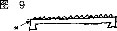
图9是椎间盘假体的一端板部分的前视图。Figure 9 is a front view of an endplate portion of a disc prosthesis.
图10是椎间盘假体的一端板部分的侧视图。Figure 10 is a side view of an endplate portion of a disc prosthesis.
图11-13是根据本发明替代实施例的椎间盘假体的俯视截面图。11-13 are top cross-sectional views of an intervertebral disc prosthesis according to an alternative embodiment of the present invention.
图14-18是根据本发明替代实施例的椎间盘假体的侧视截面图。14-18 are side cross-sectional views of an intervertebral disc prosthesis according to an alternative embodiment of the present invention.
图19是根据本发明一替代实施例的分解的椎间盘假体的侧视截面图。19 is a side cross-sectional view of an exploded disc prosthesis according to an alternative embodiment of the present invention.
图20是根据图19的实施例的组装椎间盘假体的侧视截面图。20 is a side cross-sectional view of an assembled disc prosthesis according to the embodiment of FIG. 19 .
图21是根据图19的实施例的椎间盘假体的俯视截面图。21 is a top cross-sectional view of a disc prosthesis according to the embodiment of FIG. 19 .
图22-30是根据本发明替代实施例的组装椎间盘假体的侧视截面图。22-30 are side cross-sectional views of an assembled intervertebral disc prosthesis according to an alternative embodiment of the present invention.
图31是根据本发明一替代实施例的椎间盘假体的侧视截面图。31 is a side cross-sectional view of an intervertebral disc prosthesis according to an alternative embodiment of the present invention.
图32是根据图31的实施例的椎间盘假体的俯视截面图。32 is a top cross-sectional view of a disc prosthesis according to the embodiment of FIG. 31 .
图33是根据本发明一替代实施例的椎间盘假体的侧视截面图。33 is a side cross-sectional view of an intervertebral disc prosthesis according to an alternate embodiment of the present invention.
图34是根据图33的实施例的椎间盘假体的俯视截面图。34 is a top cross-sectional view of a disc prosthesis according to the embodiment of FIG. 33 .
图35、37、39和41是根据本发明替代实施例的椎间盘假体的俯视截面图。35, 37, 39 and 41 are top cross-sectional views of intervertebral disc prostheses according to alternative embodiments of the present invention.
图36、38、40和42分别是图35、37、39和41的实施例的椎间盘假体的侧视截面图。Figures 36, 38, 40 and 42 are side cross-sectional views of the intervertebral disc prosthesis of the embodiment of Figures 35, 37, 39 and 41, respectively.
具体实施方式Detailed ways
本发明一般地涉及椎骨再造装置,具体来说,涉及一功能性的椎间盘假体。为了便于理解本发明的原理,现将参照附图中所示的实施例或实例,并用特殊的语言来描述它们。然而,应该理解到,由此并不意图限制本发明的范围。在所述实施例中的任何替代和进一步的修改,以及如本文中所述的本发明原理的任何进一步应用,对于本发明所涉及的技术领域内的技术人员来说,应认为是正常发生的。The present invention relates generally to vertebral reconstruction devices and, in particular, to a functional intervertebral disc prosthesis. In order to facilitate understanding of the principles of the present invention, specific language will now be used to describe the embodiments or examples shown in the drawings. It should be understood, however, that no limitation of the scope of the invention is thereby intended. Any substitutions and further modifications in the described embodiments, and any further application of the principles of the invention as described herein, should be considered as would normally occur to those skilled in the art to which the invention pertains .
首先参照图1,标号10表示一具有在两个完好椎骨14和16之间延伸的损坏椎间盘12的脊柱。在一典型的外科切除术中,损坏盘12被除去,在两个完好椎骨14和16之间形成一空穴。该手术程序执行可使用一前向、前侧向、侧向方法,或本技术领域内的技术人员熟知的其它的方法。Referring first to FIG. 1,
现参照图2,可提供一假体18来填充椎骨14和16之间的空穴。Referring now to FIG. 2 , a
现参照图3-5,一椎间盘假体20可用作为图2的假体18。根据本发明一实施例的椎间盘假体20包括端板组件22、24和一核心部件26。端板组件22可包括一外表面28和一内表面30。在此实施例中,表面30可相对平坦和光滑,并可具有一光滑的镜面表面。表面30还可包括一槽32。端板组件24可具有一外表面34和一内表面36。表面36可相对平坦和光滑,并可具有一光滑的镜面表面。表面36还可包括一诸如一槽那样的偶联机构37。关节的内表面30、36可以平坦且具有如本实施例中所示的镜面,然而,在替代的实施例中,关节的表面可包括槽、凹坑或其它特征,以便提高润滑性能并减小摩擦和磨损。这些表面可用任何的各种技术予以处理以提高耐磨性,例如,离子注入、金刚石或金刚石状的涂敷,或能使表面比原来表面更加坚硬的其它方法。Referring now to FIGS. 3-5 , a
核心部件26可包括一具有端表面40和42的柔性本体38。如图5所示,从一垂直于纵向轴线44(图3)的平面观看,核心部件26可具有一大致圆形的截面。可要求有替代的横截面形状,在一单一核心部件26中,横截面形状可根据垂直平面的位置变化。在此实施例中,端表面40和42可以相对地平坦和平行,并可分别地包括偶联机构46、48,它们可以是突脊。端表面40、42可与柔性本体38一体形成,或可用机械方法或粘结方法附连到柔性本体38。例如,如图4所示,一诸如突脊那样形成在柔性本体38上的偶联机构50可接合一诸如槽那样形成在端表面42上的偶联机构52。在替代的实施例中,核心部件可具有弧形端表面或相对于彼此倾斜的端表面。
端板组件22、24可以由任何合适的生物相容材料形成,包括有诸如钴铬合金、钛合金、镍钛合金之类的金属,和/或不锈钢合金。诸如氧化铝或矾土之类的陶瓷、氧化锆或锆土、特殊金刚石压块,和/或热解碳等也可适用。也可使用聚合物材料,包括任何数量的多芳基酮醚(PAEK)族,诸如聚醚酮醚(PEEK)、碳强化的PEEK,或聚醚酮醚酮醚(PEKK);聚砜;聚醚酰亚胺;聚酰亚胺;超高分子量聚乙烯(UHMWPE);和/或交连的UHMWPE。
外表面28、34可包括特征或涂层(未示出),它们提高移植的假体的固定能力。例如,表面可以粗糙化,例如,通过化学蚀刻、喷丸、砂纸打磨、磨削、刻齿纹,和/或金刚石切割。所有的或一部分的外表面28、34也可涂敷生物相容的和骨传导的材料,诸如羟磷灰石(HA)、磷酸三钙(TCP),和/或碳酸钙,以促进骨的生长和固定。或者,可使用骨传导涂层,诸如取自转化生长因子(TGF)β总科的蛋白质,或骨形态基因蛋白质,诸如BMP2或BMP7。其它合适的特征可包括用于初始固定的图6中端板组件60上所显示的长钉、图7和8中端板组件62上所显示的突脊或龙骨,以防止沿侧向和前方向的迁移,例如,图9和10中的端板组件64上所示的锯齿形或金刚石切割表面;翅片;短柱;和/或其它表面纹理。The
再次参照图3-5,柔性本体38可由一个或多个弹性材料形成,其具有比端板材料小的弹性模量。合适的材料可包括聚合物的弹性体,诸如聚烯烃橡胶;聚亚胺酯(包括聚醚聚氨酯、聚碳酸脂聚氨酯,以及聚亚胺酯,具有或没有表面修改的端板);具有或没有表面修改的端板的硅树脂和聚亚胺酯的共聚物;硅树脂;以及水凝胶。聚异丁烯橡胶、聚异戊二烯橡胶、氯丁橡胶、丁腈橡胶,和/或5-甲基-1,4-己二烯的硫化橡胶也是合适的。Referring again to FIGS. 3-5, the
核心部件端表面40、42可以修改、处理、涂敷或内衬以提高核心部件26的耐磨性和关节特性。这些耐磨性和关节特性可由钴铬合金、钛合金、镍钛合金,和/或不锈钢合金提供。诸如氧化铝或矾土之类的陶瓷、氧化锆或锆土、特殊金刚石压块,和/或热解碳等也可适用。也可使用聚合物材料,包括任何数量的多芳基酮醚(PAEK)族,诸如聚醚酮醚(PEEK)、碳强化的PEEK,或聚醚酮醚酮醚(PEKK);聚砜;聚醚酰亚胺;聚酰亚胺;超高分子量聚乙烯(UHMWPE);和/或交连的UHMWPE。聚烯烃橡胶、聚亚胺酯、硅树脂和聚亚胺酯的共聚物,以及水凝胶也可提供耐磨性和关节特性。通过诸如交连的和金属离子注入的修改,耐磨特性也可以或替代地提供给端表面40、42。The core component end surfaces 40 , 42 may be modified, treated, coated or lined to enhance the wear resistance and articulation properties of the
尽管图3-5的实施例描述了圆形的端板组件,但图11示出了一矩形的端板组件66。图12示出一带有弧形侧的矩形端板组件68。图13示出一腰子形或心形的端板组件70。其它端板几何形可以是正方形、椭圆形、三角形、六角形,或任何其它形状。如图5的俯视横截面图所示,核心部件的几何形可以是圆形、椭圆形,或促进约束或关节连接的任何其它形状。While the embodiments of FIGS. 3-5 depict circular end plate assemblies, FIG. 11 shows a rectangular end plate assembly 66 . Figure 12 shows a rectangular
在图3-5的实施例中,外表面28和34可以相对地平行,但在其它实施例中,表面可以相对于彼此倾斜以容纳一特殊的脊柱前凸或前弯角。如图14-18所示,假体可以是锥形、倾斜,或楔形以便达到一理想的脊柱前凸或前弯角。这样的角度可以通过包括倾斜的端板组件和/或核心部件而形成。图14的假体72结合一倾斜端板而呈倾斜。而图15的假体74通过包括两个倾斜端板而呈倾斜。图16的假体76通过包括带有一具有一倾斜侧的核心部件的平的端板而呈倾斜。图17的假体78通过包括带有一具有两个倾斜侧的核心部件的平的端板而呈倾斜。图18的假体80通过包括一倾斜端板和具有一个倾斜侧的核心部件而呈倾斜。In the embodiment of FIGS. 3-5,
再次参照图4,假体20可通过核心部件26的突脊46、48分别与端板组件的槽32、37接合进行组装。组装的假体20可以移植到脊柱10(图1)内的通过移去盘12而形成的空穴内,以使外表面28接合椎骨体14的端板,而外表面34接合椎骨体16的端板。Referring again to FIG. 4, the
在手术中,假体20可在平行于纵向轴线44的压缩载荷下弹性地变形,并可响应于沿纵向轴线44拉端板组件彼此远离的力而弹性地伸展。假体20也可在弯曲延伸下变形或侧向地弯曲移动。核心部件26可允许一可变的转动中心以作弯曲延伸和侧向弯曲移动。核心部件26的柔软特性也可减小在弯曲延伸和侧向弯曲移动中由横向剪切或关节连接造成的磨损。核心部件26也可弯曲以允许端板组件22相对于端板组件24作前-后或侧向的平移。此外,端表面40、42和内表面30、36之间的接触面相应地转动不受约束,核心部件26可围绕纵向轴线44枢转或转动。然而,接触面可以约束接触面处的平移运动。端板组件22、24也可相对于彼此转动。在替代的实施例中,端表面40、42和内表面30、36之间的至少一个接触面对应地可允许不转动或枢转运动。核心部件26的偶联机构46、48与偶联机构32、37的接合可防止核心部件26的弹出,同时允许端板组件22、24相对于核心部件转动。In surgery, the
现参照图19-21,一椎间盘假体90可用作为图2的假体18。根据本发明的一实施例,椎间盘假体90包括端板组件92、94和一核心部件96。端板组件92可包括一外表面98和一内表面100。在此实施例中,内表面100可以相对地呈凹陷和光滑并可具有一镜面光滑的表面。端板组件94可具有一外表面104和一内表面106。表面106可以相对地呈凹陷和光滑并可具有一镜面光滑的表面。在此实施例中,外表面98和104相对地平行,但在其它实施例中,如上所述,诸表面可相对于彼此倾斜以容纳一特殊的脊柱前凸或前弯角。Referring now to FIGS. 19-21 , a
核心部件96可包括一具有端表面110和112的柔性本体108。如图21所示,当从一垂直于纵向轴线44的平面观看时,核心部件96可具有一大致圆形的截面。也可要求有替代的其它横截面形状,在单一核心部件96中,横截面形状可根据垂直平面的位置而变化。在此实施例中,表面110和112可以相对地呈凸出。端表面110、112可以与柔性本体118一体形成,或可机械地或粘结地附连到柔性本体118。例如,诸如一形成在柔性本体108上的突脊那样的偶联机构114可接合诸如形成在端表面112上的槽那样的偶联机构116。
端板组件92、94可分别用与端板组件22、24相同或类似的材料形成,包括相同的或类似的特征或涂层。同样地,核心部件96可用如上对于核心部件26所述的相同材料形成并可包括相同的耐磨性。假体90;端板组件92、94;以及核心部件96可形成上述图6-18中的形状。
如图20所示,假体90可通过分别定位与内表面100、106接触的端表面110、112进行组装。组装的假体90可植入到由移去盘12而形成的空穴内的脊柱10内(图1),以使外表面98接合椎骨体14的端板,而外表面104接合椎骨体16的端板。As shown in FIG. 20, the
在手术中,假体90可在平行于纵向轴线44的压缩载荷下弹性地变形。假体90也可在弯曲延伸下变形或侧向地弯曲移动。核心部件96也可弯曲以允许作前后或侧向平移移动。核心部件96可允许一可变的转动中心以作弯曲延伸和侧向弯曲移动。核心部件96的柔软特性也可减小在弯曲延伸和侧向弯曲移动中由横向剪切或关节连接造成的磨损。此外,由于端表面110、112和内表面100、106之间的接触面相应地不受约束,核心部件96可围绕纵向轴线44转动。端板组件92、94也可相对于彼此转动。凹陷的内表面100、106可防止核心部件26的弹出,同时允许端板组件22、24相对于核心部件转动。During surgery, the
如图22-27所示,各种替代的端板组件、核心部件以及偶联机构的设计可限制侧向的平移,同时允许轴向的转动。例如,现参照图22,一椎间盘假体120可用作为图2的假体18。椎间盘假体120包括端板组件122、124和一核心部件126。端板组件122、124可包括相应的外表面128、130和内表面132、134。内表面132、134可包括凹陷和凸出的部分并可如一镜面表面那样地光滑。凹陷和凸出部分可在内表面上形成同心环。在图22的实施例中,内表面132、134的凸出部分136、138可起作偶联机构。端板组件122、124可分别用与端板组件22、24相同的或类似的材料形成,包括相同的或类似的特征或涂层。As shown in Figures 22-27, various alternative endplate assembly, core member, and coupling designs limit lateral translation while allowing axial rotation. For example, referring now to FIG. 22, a
核心部件126可包括一具有端表面142、144的柔性本体140。在此实施例中,端表面142、144可包括偶联机构146、148,它们可以是近似位于端表面中心内的凹坑。核心部件126可用对于核心部件26所述的相同材料形成,并可包括如上相同耐磨特性。The
假体120可通过分别定位与内表面132、134接触的端表面142、144进行组装。具体来说,端板组件的偶联机构136、138可接合核心部件的偶联机构146、148。组装的假体120可植入到由移去盘12而形成的空穴内的脊柱10内(图1),以使外表面128接合椎骨体14的端板,而外表面130接合椎骨体16的端板。
现参照图23,一椎间盘假体150可用作为图2的假体18。椎间盘假体150包括呈圆形的端板组件152、154和一核心部件156。端板组件152、154可分别包括外表面158、160和内表面162、164。与图22实施例相同,内表面162、164可包括凹陷和凸出部分,并可如镜面那样光滑。凹陷和凸出部分可在内表面上形成同心环。在此实施例中,内表面162、164的凸出环部分166、168可起作偶联机构,以对应地接合形成在核心部件156的端表面174、176上的凹陷的偶联机构170、172。Referring now to FIG. 23, an
现参照图24,一椎间盘假体180可用作为图2的假体18。根据本发明的该实施例,假体180包括端板组件182、184和一核心部件186。端板组件182、184可分别包括外表面188、190和内表面192、194。内表面192、194可包括凹陷和凸出部分,并可如镜面那样光滑。在图24的实施例中,内表面192、194的凸出环部分196、198可起作偶联机构。端板组件182、184可对应地用与端板组件22、24相同的或类似的材料形成,包括相同的或类似的特征或涂层。Referring now to FIG. 24, an
核心部件186可包括一具有关节表面202的柔性本体200。在此实施例中,端板组件186可以呈环的形状,具有一中心孔204,其可起作一偶联机构。核心部件186可用以上对于核心部件26所述的相同材料形成,并可包括相同的耐磨特性。
假体180可通过分别定位与内表面190、194之间的核心部件196进行组装。具体来说,端板组件的偶联机构196、198可接合核心部件的偶联机构204。组装的假体180可植入到由移去盘12而形成的空穴内的脊柱10内(图1),以使外表面188接合椎骨体14的端板,而外表面192接合椎骨体16的端板。
在手术中,关节表面202和内表面190、194之间的接触面可允许围绕纵向轴线44转动和有限的侧向平移。假体180可在平行于纵向轴线44的压缩载荷下弹性地变形以吸收冲击和提供阻尼作用。端板组件182、184和核心部件186之间的关节接触面,以及柔性本体200的弹性可允许作弯曲延伸和侧向弯曲运动。During surgery, the interface between the
现参照图25,一椎间盘假体210可用作为图2的假体18。根据本发明的该实施例,椎间盘假体210包括端板组件212、214和一核心部件216。端板组件212可分别包括一外表面218和一内表面220。在图25的实施例中,内表面220可相对地凹陷和光滑,并可具有镜面那样光滑。端板组件214可具有一外表面222和一内表面224。内表面224可以相对地凹陷并可包括一偶联机构226,该机构可以是一突出的短柱。Referring now to FIG. 25, an intervertebral disc prosthesis 210 may be used as the
核心部件216可包括一柔性层228和附连到柔性层228的外关节层230、232。关节层230可以是凸出的。关节层232可大致地呈凸出,并可包括一用作为偶联机构的凹陷234。在一替代的实施例中,凹陷可以形成在关节层230上。The core component 216 may include a flexible layer 228 and outer articulating layers 230 , 232 attached to the flexible layer 228 . The joint layer 230 may be convex. Articulating layer 232 may be generally convex and may include a recess 234 that acts as a coupling mechanism. In an alternative embodiment, depressions may be formed on the joint layer 230 .
端板组件212、214可对应地用与端板组件22、24相同的或类似的材料形成,包括相同的或类似的特征或涂层,因此不再作详细的描述。柔性层228可用与以上对于核心部件26所述的相同的柔性或弹性材料形成。关节层230、232可用与端板组件22、24相同或类似的材料形成。或者,关节层230、232可用与以上对于核心部件26所述的相同或类似的材料形成,仅在交连或离子注入方面有修改以提高耐磨性能。The end plate assemblies 212, 214 may respectively be formed from the same or similar materials as the
如图25所示,假体210可通过端板组件212的凹陷内表面220与核心部件216的凸出关节层230的接合进行组装。通过偶联机构234接合偶联机构226,关节层232可接合端板组件214的内表面224。As shown in FIG. 25 , the prosthesis 210 may be assembled by engagement of the concave inner surface 220 of the endplate assembly 212 with the convex articular layer 230 of the core component 216 . With coupling mechanism 234 engaging coupling mechanism 226 , articulating layer 232 may engage inner surface 224 of endplate assembly 214 .
在手术中,凸出的关节表面230和端板组件212的凹陷表面220之间的接触面可允许围绕纵向轴线44转动和有限的侧向平移。关节层232可允许围绕内表面224的偶联机构226转动,同时允许核心部件216和端板组件214之间很小或没有侧向平移。假体210可在平行于纵向轴线44的压缩载荷下弹性地变形以吸收冲击和提供阻尼作用。端板组件212和核心部件216之间的关节接触面,以及柔性层228的弹性可允许作弯曲延伸和侧向弯曲运动,或围绕纵向轴线44作轴向转动。During surgery, the interface between the convex articulating surface 230 and the concave surface 220 of the endplate assembly 212 may allow rotation about the
现参照图26,一椎间盘假体240可用作为图2的假体18。根据本发明的该实施例,椎间盘假体240包括端板组件242、244和一核心部件246。端板组件242可分别包括一外表面248和一内表面250。在图26的实施例中,内表面250可相对地凹陷和光滑,并可具有镜面那样光滑。Referring now to FIG. 26, an intervertebral disc prosthesis 240 may be used as the
端板组件244可具有一外表面252和一内表面254。内表面254可以相对地平坦并可包括一偶联机构256,该机构可以是一突出的短柱,而偶联机构258可以是一槽。End plate assembly 244 may have an outer surface 252 and an inner surface 254 . Inner surface 254 may be relatively flat and may include a coupling mechanism 256, which may be a protruding stud, and coupling mechanism 258, which may be a groove.
核心部件246可包括一柔性层260和附连到柔性层260的外关节层262、264。关节层262可以是凸出的。关节层264可相对地呈平坦,并可包括一突脊266和一凹坑268,它们两个可用作为偶联机构。The core component 246 may include a flexible layer 260 and outer articulating layers 262 , 264 attached to the flexible layer 260 . The joint layer 262 may be convex. Articulating layer 264 may be relatively flat and may include a ridge 266 and a dimple 268, both of which may serve as a coupling mechanism.
端板组件242、244可对应地用与端板组件22、24相同的或类似的材料形成,包括相同的或类似的特征或涂层,因此不再作详细的描述。柔性层260可用与以上对于核心部件26所述的相同的柔性或弹性材料形成。关节层262、264可用与端板组件22、24相同或类似的材料形成。或者,关节层262、264可用与以上对于核心部件26所述的相同或类似的材料形成,仅在交连或离子注入方面有修改以提高耐磨性能。End plate assemblies 242, 244 may be formed from the same or similar materials as
如图26所示,假体240可通过端板组件242的凹陷内表面250与核心部件246的凸出关节层262的接合进行组装。通过偶联机构266、268分别接合偶联机构258、256,关节层264可接合端板组件244的内表面254。As shown in FIG. 26 , the prosthesis 240 may be assembled by engagement of the concave inner surface 250 of the endplate assembly 242 with the convex articular layer 262 of the core component 246 . Articulating layer 264 may engage inner surface 254 of endplate assembly 244 by coupling mechanisms 266 , 268 engaging coupling mechanisms 258 , 256 , respectively.
在手术中,凸出的关节层262和端板组件242的凹陷表面250之间的接触面可允许围绕纵向轴线44转动和有限的侧向平移。关节层264可允许围绕轴线44相对于内表面254转动,或者,接触面可以机械地或粘结地固定到本转动。假体240可在平行于纵向轴线44的压缩载荷下弹性地变形以吸收冲击和提供阻尼作用。端板组件242和核心部件246之间的关节接触面,以及柔性层262的弹性可允许作弯曲延伸和侧向弯曲运动,或围绕纵向轴线44作轴向转动。During surgery, the interface between the raised articular layer 262 and the concave surface 250 of the endplate assembly 242 may allow rotation about the
现参照图27,一椎间盘假体270可用作为图2的假体18。根据本发明的该实施例,椎间盘假体270包括端板组件272、274和一核心部件276。端板组件272可分别包括一外表面278和一内表面280。在图27的实施例中,内表面280可包括呈同心圆、燕尾槽的偶联机构282。Referring now to FIG. 27, an intervertebral disc prosthesis 270 may be used as the
端板组件274可具有包括一外表面284和一内表面286。内表面286可相对地光滑和凹陷,并可具有镜表面的光滑。The end plate assembly 274 may have an outer surface 284 and an inner surface 286 . The inner surface 286 may be relatively smooth and concave, and may have the smoothness of a mirror surface.
核心部件276可包括一柔性层288和附连到柔性层290的外关节层290、292。关节层292可以是凸出的。关节层290可包括平坦部分,并可包括呈同心圆、燕尾形突出的偶联机构294。Core component 276 may include a flexible layer 288 and outer articulating layers 290 , 292 attached to flexible layer 290 . Articulation layer 292 may be convex. Articulating layer 290 may include a flat portion, and may include coupling mechanisms 294 that protrude in the shape of concentric circles, dovetails.
端板组件272、274可对应地用与端板组件22、24相同的或类似的材料形成,包括相同的或类似的特征或涂层。柔性层288可用与以上对于核心部件26所述的相同的柔性或弹性材料形成。关节层290、292可用与端板组件22、24相同或类似的材料形成。或者,关节层290、292可用与以上对于核心部件26所述的相同或类似的材料形成,仅在交连或离子注入方面有修改以提高耐磨性能。The end plate assemblies 272, 274 may be formed from the same or similar materials as the
如图27所示,假体270可通过端板组件274的凹陷内表面286与核心部件276的凸出关节层292的接合进行组装。通过偶联机构282接合偶联机构294,关节层290可接合端板组件272的内表面280。As shown in FIG. 27 , the prosthesis 270 may be assembled by engagement of the concave inner surface 286 of the endplate assembly 274 with the convex articular layer 292 of the core component 276 . With coupling mechanism 282 engaging coupling mechanism 294 , articular layer 290 may engage inner surface 280 of endplate assembly 272 .
在手术中,凸出的关节层292和端板组件274的凹陷表面286之间的接触面可允许围绕纵向轴线44转动和有限的侧向平移。关节层290可允许围绕轴线44相对于内表面280转动,同时,偶联机构282、294阻止或限制侧向运动。假体270可在平行于纵向轴线44的压缩载荷下弹性地变形以吸收冲击和提供阻尼作用。端板组件274和核心部件276之间的关节接触面,以及柔性层288的弹性可允许作弯曲延伸和侧向弯曲运动,或围绕纵向轴线44作轴向转动。在一替代的实施例中,诸如用于标号282、294的偶联机构可用于端板组件274和核心部件276之间的接触面。在此替代实施例中,侧向平移可被阻止或限制,而仍允许围绕轴线44转动。在此替代实施例中的核心部件的柔性仍可作弯曲延伸和侧向弯曲运动。During surgery, the interface between the raised articular layer 292 and the concave surface 286 of the endplate assembly 274 may allow rotation about the
现参照图28,一椎间盘假体300可用作为图2的假体18。根据本发明的另一实施例,椎间盘假体300包括端板组件302、304和一核心部件306。端板组件302可包括一外表面308和一内表面310。在图28的实施例中,内表面310可以是相对的凹陷和光滑,并具有镜面那样的光滑。Referring now to FIG. 28, an intervertebral disc prosthesis 300 may be used as the
端板组件304可具有一外表面314和一内表面316。内表面316可相对地平坦,并可包括一呈槽的偶联机构318。外表面308和314可相对地平行和相对于彼此倾斜,以容纳特殊的脊柱前凸或前弯角。End plate assembly 304 may have an outer surface 314 and an inner surface 316 . The inner surface 316 may be relatively flat and may include a coupling mechanism 318 in the form of a groove. Outer surfaces 308 and 314 may be relatively parallel and sloped relative to each other to accommodate particular lordotic or lordotic angles.
核心部件306可包括一柔性层320和一附连到柔性层320的关节层322。关节层322可具有一凸出表面324。柔性层320可包括呈突脊的一偶联机构326。核心部件306可具有一大致圆形的横截面(如从一垂直于纵向轴线44的平面观看)。替代的横截面形状也是理想的,在一单一的核心部件306中,横截面形状可以根据垂直平面的位置变化。Core component 306 may include a flexible layer 320 and an articulating layer 322 attached to flexible layer 320 . The joint layer 322 may have a convex surface 324 . The flexible layer 320 may include a coupling mechanism 326 in the form of a ridge. The core member 306 may have a generally circular cross-section (eg, as viewed from a plane perpendicular to the longitudinal axis 44 ). Alternative cross-sectional shapes are also desirable, and within a single core member 306, the cross-sectional shape may vary according to the position of the vertical plane.
端板组件302、304可对应地用与端板组件22、24相同的或类似的材料形成,包括相同的或类似的特征或涂层,因此,不再作详细的描述。柔性层320可用与以上对于核心部件26所述的相同的柔性或弹性材料形成。关节层322可用与端板组件22、24相同或类似的材料形成。或者,关节层322可用与以上对于核心部件26所述的相同或类似的材料形成,仅在交连或离子注入方面有修改以提高耐磨性能。The end plate assemblies 302, 304 may respectively be formed from the same or similar materials as the
如图28所示,假体300可通过机械地或粘结地将柔性层320附连到端板组件304的内表面316进行组装。偶联机构318可接合偶联机构326,提供机械的附连。附加地或替换地,可使用一粘结剂来附连柔性层320和内表面316。关节层322的凸出表面324可定位在凹陷的内表面310上。组装的部件302-306可植入到由移去盘12而形成的空穴内的脊柱内(图1),以使外表面308接合椎骨体14的端板,而外表面314接合椎骨体16的端板。As shown in FIG. 28 , the prosthesis 300 may be assembled by mechanically or adhesively attaching the flexible layer 320 to the inner surface 316 of the endplate assembly 304 . Coupling mechanism 318 may engage coupling mechanism 326 to provide mechanical attachment. Additionally or alternatively, an adhesive may be used to attach the flexible layer 320 and the inner surface 316 . The convex surface 324 of the articular layer 322 can be positioned on the concave inner surface 310 . The assembled components 302-306 can be implanted into the spinal column (FIG. 1) in the cavity formed by removing the
在手术中,关节层322的凸出表面324可与端板组件92的凹陷表面310形成关节连接。假体300可在平行于纵向轴线44的压缩载荷下弹性地变形以吸收冲击和提供阻尼作用。端板组件302和核心部件306之间的关节接触面,以及柔性层320的弹性可允许作弯曲延伸和侧向弯曲运动,或围绕纵向轴线44作轴向转动。端板组件302、304也可相对于彼此转动。During surgery, the convex surface 324 of the articular layer 322 may articulate with the concave surface 310 of the
现参照图29,一椎间盘假体330可用作为图2的假体18。根据本发明的另一实施例,椎间盘假体330包括端板组件332、334和一核心部件336。端板组件332可包括一外表面338和一内表面340。在图16的实施例中,内表面340可以是相对的平坦,并包括一可以是槽的偶联机构342。Referring now to FIG. 29, a
端板组件334可具有一外表面344和一内表面346。内表面346可以至少部分地凸出并可如镜面那样光滑。外表面338和344可相对地平行或可相对于彼此倾斜,以容纳特殊的脊柱前凸或前弯角。
核心部件336可包括一柔性层350和一附连到柔性层350的关节层352。关节层352可具有一凹陷表面354。柔性层350可包括呈突脊的一偶联机构356。核心部件336可具有一大致圆形的横截面(如从一垂直于纵向轴线44的平面观看)。替代的横截面形状也是理想的,在一单一的核心部件336中,横截面形状可以根据垂直平面的位置变化。
端板组件332、334可对应地用与端板组件22、24相同的或类似的材料形成,包括相同的或类似的特征或涂层,因此,不再作详细的描述。柔性层350可用与以上对于核心部件26所述的相同的柔性或弹性材料形成。关节层352可用与端板组件22、24相同或类似的材料形成。或者,关节层352可用与以上对于核心部件26所述的相同或类似的材料形成,仅在交连或离子注入方面有修改以提高耐磨性能。The
如图29所示,假体330可通过机械地或粘结地将柔性层350附连到端板组件332的内表面340进行组装。偶联机构342可接合偶联机构356,提供机械的附连。附加地或替换地,可使用一粘结剂来附连柔性层350和内表面340。关节层352的凹陷表面354可定位在凸出的内表面346上。组装的部件332-336可植入到由移去盘12而形成的空穴内的脊柱10内(图1),以使外表面338接合椎骨体14的端板,而外表面344接合椎骨体16的端板。As shown in FIG. 29 , the
在手术中,关节层352的凹陷表面354可与端板组件334的凸出表面346形成关节连接。假体330可在平行于纵向轴线44的压缩载荷下弹性地变形以吸收冲击和提供阻尼作用。端板组件334和核心部件336之间的关节接触面,以及柔性层350的弹性可允许作弯曲延伸和侧向弯曲运动,或围绕纵向轴线44作轴向转动。端板组件332、334也可相对于彼此转动。During surgery, the
现参照图30,一椎间盘假体360可用作为图2的假体18。根据本发明的另一实施例,椎间盘假体360包括端板组件362、364、一核心部件366和一核心部件367。端板组件362可包括一外表面368和一内表面370。在图30的实施例中,内表面370可以是相对的平坦,并包括一可以是槽的偶联机构372。Referring now to FIG. 30, a
端板组件364可包括一外表面374和一内表面376。在图30的实施例中,内表面376可以相对地平坦并可包括可以是一槽的偶联机构378。外表面368和374可相对地平行或可相对于彼此倾斜,以容纳特殊的脊柱前凸或前弯角。
核心部件366可包括一柔性层380和一附连到柔性层380的关节层382。关节层382可具有一凹陷表面384。柔性层380可包括呈突脊的一偶联机构386。核心部件366可具有一大致圆形的横截面(如从一垂直于纵向轴线44的平面观看)。替代的横截面形状也是理想的,在一单一的核心部件366中,横截面形状可以根据垂直平面的位置变化。
核心部件367可包括一柔性层388和一附连到柔性层388的关节层390。关节层390可具有一凸出表面392。柔性层388可包括呈突脊的一偶联机构394。核心部件367可具有一大致圆形的横截面(如从一垂直于纵向轴线44的平面观看)。替代的横截面形状也是理想的,在一单一的核心部件367中,横截面形状可以根据垂直平面的位置变化。
端板组件362、364可对应地用与端板组件22、24相同的或类似的材料形成,包括相同的或类似的特征或涂层,因此,不再作详细的描述。柔性层380、388可用与以上对于核心部件26所述的相同的柔性或弹性材料形成。关节层382、390可用与端板组件22、24相同或类似的材料形成。或者,关节层382、390可用与以上对于核心部件26所述的相同或类似的材料形成,仅在交连或离子注入方面有修改以提高耐磨性能。The
如图30所示,假体360可通过机械地或粘结地将柔性层380附连到端板组件362的内表面370进行组装。偶联机构372可接合偶联机构386,提供机械的附连。附加地或替换地,可使用一粘结剂来附连柔性层380和内表面370。柔性层388可机械地和/或粘结地附连到端板组件364的内表面376。偶联机构378可接合偶联机构394,提供机械的附连。附加地或替换地,可使用一粘结剂来附连柔性层388和内表面376。关节层382的凹陷表面384可定位在凸出的关节表面392上。组装的部件可植入到由移去盘12而形成的空穴内的脊柱10内(图1),以使外表面368接合椎骨体14的端板,而外表面374接合椎骨体16的端板。As shown in FIG. 30 , the
在手术中,关节层382的凹陷表面384可与关节层390的凸出表面392形成关节连接。假体360可在平行于纵向轴线44的压缩载荷下弹性地变形以吸收冲击和提供阻尼作用。核心部件366和核心部件367之间的关节接触面,以及柔性层380的弹性可允许作弯曲延伸和侧向弯曲运动,或围绕纵向轴线44作轴向转动。端板组件362、364也可相对于彼此转动。During surgery, the
现参照图31-32,一椎间盘假体400可用作为图2的假体18。根据本发明的该实施例,椎间盘假体400包括端板组件402、404和一核心部件406。端板组件402可包括一外表面408和一内表面410。在图31的实施例中,内表面410可包括一相对地凹陷的部分,其可以是如镜面那样光滑。端板组件404可具有一外表面412和一内表面414。内表面414可包括一相对地凹陷的部分。可以是缓冲器的偶联机构416可从内表面410、414突出。Referring now to FIGS. 31-32, an intervertebral disc prosthesis 400 may be used as the
核心部件406可包括一柔性层418和附连到柔性层418的外关节层420、422。关节层420、422可包括可以是槽的偶联机构424。一个或多个系带426可在端板组件402和404之间延伸。The core component 406 may include a flexible layer 418 and outer articulating layers 420 , 422 attached to the flexible layer 418 . The articulating layers 420, 422 may include a coupling mechanism 424, which may be a slot. One or more ties 426 may extend between end plate assemblies 402 and 404 .
端板组件402、404可对应地用与端板组件22、24相同的或类似的材料形成,包括相同的或类似的特征或涂层,因此,不再作详细的描述。柔性层418可用与以上对于核心部件26所述的相同的柔性或弹性材料形成。关节层420、422可用与端板组件22、24相同或类似的材料形成。或者,关节层420、422可用与以上对于核心部件26所述的相同或类似的材料形成,仅在交连或离子注入方面有修改以提高耐磨性能。系带426可以是弹性的或非弹性的。例如,它们可以是由诸如钢丝、缆索、线、带、带子,或板那样的加强材料形成。它们可用以上对于端板组件22、24或核心部件26所述的任何材料形成(诸如UHMWPE)。在某些实施例中,系带426可以是编结的、针织的或纺织的。End plate assemblies 402, 404 may respectively be formed from the same or similar materials as
如图31所示,假体400可通过将核心部件406定位在端板组件402、404的内表面410、414之间进行组装。缓冲器416可定位成沿关节层420、422的槽424移动。某些实施例可具有两个和四个缓冲器/槽之间的接触面。一个或多个系带426可在端板组件402、404之间延伸,以提供附加的稳定性和/或在经受弯曲/延伸、侧向弯曲或轴向转动力时对假体400提供附加的约束。如图31所示,系带426可在端板组件402、404之间延伸,而不通过核心部件406。组装的假体400可定位在椎骨14、16之间的脊柱10内。As shown in FIG. 31 , the prosthesis 400 may be assembled by positioning the core component 406 between the inner surfaces 410 , 414 of the endplate assemblies 402 , 404 . The bumper 416 may be positioned to move along the slot 424 of the joint layers 420 , 422 . Certain embodiments may have between two and four bumper/slot interfaces. One or more tethers 426 may extend between the endplate assemblies 402, 404 to provide additional stability and/or to provide additional support to the prosthesis 400 when subjected to bending/extension, lateral bending, or axial rotational forces. constraint. As shown in FIG. 31 , the ties 426 may extend between the end plate assemblies 402 , 404 without passing through the core member 406 . The assembled prosthesis 400 may be positioned within the
再次参照图31-32,在手术中,缓冲器416可沿关节层420、422的槽424移动,允许围绕纵向轴线44作有限的转动。与缓冲器416的长度相比,该转动由槽424的长度限制。例如,几乎与槽424同长的缓冲器416将允许很小或没有转动。在某些实施例中,1和20度之间的转动是许可的。某些实施例可将转动限制到3和10度之间。系带426也可在弯曲/延伸、侧向弯曲和/或轴向转动运动中约束假体400。在组件的约束内,假体400可在平行于纵向轴线44的压缩载荷下弹性地变形以吸收冲击和提供阻尼作用。端板组件402、404和核心部件406之间的关节接触面以及柔性层418的弹性可允许弯曲延伸、侧向弯曲或围绕纵向轴线44的轴向转动运动。Referring again to FIGS. 31-32 , the bumper 416 is movable along the slot 424 of the articular layers 420 , 422 allowing limited rotation about the
现参照图33-34,一椎间盘假体430可用作为图2的假体18。根据本发明的该实施例,椎间盘假体430包括端板组件432、434和一核心部件436。端板组件432可包括一内表面438。在图33的实施例中,内表面438可包括一相对地凹陷的部分,其可以是如镜面那样光滑。端板组件434可具有一内表面440。内表面440可包括一相对地凹陷的部分。可以是缓冲器的偶联机构441可从内表面438、440突出。Referring now to FIGS. 33-34, an
核心部件436可包括一柔性层442和附连到柔性层442的外关节层444、446。关节层444、446可包括可以是槽的偶联机构447。一个或多个系带448可在关节层444、446之间延伸,沿对角方向通过柔性层442。附加地或替代地,一个或多个系带449可在关节层444、446之间延伸,相对地平行于轴线44通过柔性层442。The
端板组件432、434可对应地用与端板组件22、24相同的或类似的材料形成,包括相同的或类似的特征或涂层,因此,不再作详细的描述。柔性层442可用与以上对于核心部件26所述的相同的柔性或弹性材料形成。关节层444、446可用与端板组件22、24相同或类似的材料形成。或者,关节层444、446可用与以上对于核心部件26所述的相同或类似的材料形成,仅在交连或离子注入方面有修改以提高耐磨性能。系带448、449可以是弹性的或非弹性的。例如,它们可以是由诸如钢丝、缆索、线、带、带子,或板那样的加强材料形成。它们可用以上对于端板组件22、24或核心部件26所述的任何材料形成(诸如UHMWPE)。在某些实施例中,系带448、449可以是编结的、针织的或纺织的。
如图33所示,假体430可通过将核心部件436定位在端板组件432、434的内表面438、440之间进行组装。缓冲器441可定位成沿关节层444、446的槽447移动。某些实施例可具有两个和四个缓冲器/槽之间的接触面。一个或多个系带448、449可在关节层444、446之间延伸,以提供附加的稳定性和/或在经受弯曲/延伸、侧向弯曲或轴向转动力时对假体430提供附加的约束。组装的假体430可定位在椎骨14、16之间的脊柱10内。As shown in FIG. 33 , the
在手术中,缓冲器441可沿关节层444、446的槽447移动,允许围绕纵向轴线44作有限的转动。与缓冲器441的长度相比,该转动可由槽447的长度限制。例如,几乎与槽447同长的缓冲器441将允许很小或没有转动。在某些实施例中,1和20度之间的转动是许可的。某些实施例可将转动限制到3和10度之间。系带448、449也可在弯曲/延伸、侧向弯曲和/或轴向转动运动中约束假体430。例如,对角地布置的系带448可在槽447冲击缓冲器441时加强柔性层442以抵抗扭转剪切。系带448、449可单独地或彼此组合地使用。在组件的约束内,假体430可在平行于纵向轴线44的压缩载荷下弹性地变形以吸收冲击和提供阻尼作用。端板组件432、434和核心部件436之间的关节接触面以及柔性层442的弹性可允许弯曲延伸、侧向弯曲或围绕纵向轴线44的轴向转动运动。During surgery,
现参照图35-36,一椎间盘假体450可用作为图2的假体18。椎间盘假体450可包括端板组件452、454和一核心部件456并可包括上述假体的任何结构。核心部件456可包括一柔性层458,它可包括一个或多个变态元件460。柔性层458可以由与以上对于核心部件26所述的相同的柔性或弹性材料形成。Referring now to FIGS. 35-36, an
如图35-36,假体450包括两个腰子形状的变态元件460(如从图36的俯视截面图中观看)。该假体450可以植入,以使变态元件460之一位于前面位置,而一个位于后面位置,以促进或限制延伸和/或弯曲运动。或者,假体450可转动和植入,以使变态元件460侧向地定位,促进或限制侧向弯曲。35-36, the
如图37-38所示,一假体470可包括一具有一单一变态元件474的核心部件472。在此实施例中,单一变态元件474可位于核心部件472中心附近,致使核心部件的中心区域显现不同于核心部件圆周区域的刚度。单一变态元件474可形成为任何几何形,包括一球体或一椭球体。变态元件474可具有耐磨的圆形边缘。As shown in FIGS. 37-38 , a
如图39-40所示,一假体490可包括一具有一单一变态元件494的核心部件492。在此实施例中,变态元件494可以是核心部件492内的一环形区域。As shown in FIGS. 39-40 , a
如图41-42所示,一假体500可包括一具有散布在全部核心部件内的多个变态元件514的核心部件512。As shown in Figures 41-42, a prosthesis 500 may include a
变态元件460、474、494、514可以是材料和/或空穴,其控制、调整或修改硬度、刚度、柔度,或相邻柔性层的顺从性。变态元件460、474、494、514可以是任何尺寸、形状或材料,以允许核心部件456、472、492、512的刚度对应地变化。例如,核心部件456、472、492、512的某些区域可对应地设置有变态元件460、474、494、514,以在修改区域和非修改区域之间提供不同的刚度。可使用各种变态元件的结构来改变核心部件的刚度,以上所述只是几个实例。变态元件可以是在柔性层内的离散本体,或可具有一梯度的质量,其允许变态元件混合到柔性层内,例如,沿着一径向方向。
变态元件460、474、494和514可分别由不同于核心部件456、472、492、512的材料形成,包括以上对于端板组件22、24或核心部件26所述的任何材料。材料可以比柔性层的材料更刚或更柔。变态元件460、474、494和514可以是空隙,而在某些实施例中,一个或多个空隙可起作容纳治疗药的容器,诸如止痛剂、抗发炎物质、生长因子、抗生素、类固醇、块状药物,或各种药物的组合。生长因子可包括任何数量族的转化生长因子beta(TGF-beta)、骨形成素蛋白质(BMP)、重组体人类骨形成素蛋白质(rh BMP)、胰岛素状生长因子、血小板衍生的生长因子、纤维原细胞生长因子,或任何帮助促进周围组织的组织修理的其它生长因子。
尽管以上仅详细地描述了本发明几个示范的实施例,但本技术领域内的技术人员容易地认识到,在不脱离本发明新颖内容和优点的前提下,示范实施例中可作出许多修改。因此,所有如此的修改都欲包括在由附后权利要求书所定义的本发明的范围之内。在权利要求书中,装置加功能方式描述的条款意图涵盖本文所描述的作为执行所陈述功能的结构,不仅是结构的等价物,而且是等价的结构。Although only a few exemplary embodiments of the present invention have been described in detail above, those skilled in the art will readily recognize that many modifications can be made in the exemplary embodiments without departing from the novel contents and advantages of the present invention. . Accordingly, all such modifications are intended to be included within the scope of this invention as defined in the appended claims. In the claims, means-plus-function clauses are intended to cover the structures described herein as performing the recited function and not only structural equivalents but also equivalent structures.
Claims (60)
Applications Claiming Priority (2)
| Application Number | Priority Date | Filing Date | Title |
|---|---|---|---|
| US10/765,260 US7250060B2 (en) | 2004-01-27 | 2004-01-27 | Hybrid intervertebral disc system |
| US10/765,260 | 2004-01-27 |
Publications (1)
| Publication Number | Publication Date |
|---|---|
| CN1925817A true CN1925817A (en) | 2007-03-07 |
Family
ID=34795441
Family Applications (1)
| Application Number | Title | Priority Date | Filing Date |
|---|---|---|---|
| CNA2005800065791A Pending CN1925817A (en) | 2004-01-27 | 2005-01-26 | Hybrid intervertebral disc system |
Country Status (7)
| Country | Link |
|---|---|
| US (2) | US7250060B2 (en) |
| EP (1) | EP1715819A1 (en) |
| JP (1) | JP2007519488A (en) |
| CN (1) | CN1925817A (en) |
| AU (1) | AU2005209281A1 (en) |
| CA (1) | CA2554576A1 (en) |
| WO (1) | WO2005072660A1 (en) |
Cited By (6)
| Publication number | Priority date | Publication date | Assignee | Title |
|---|---|---|---|---|
| CN101980672A (en) * | 2008-03-25 | 2011-02-23 | 梅迪凯瑞国际 | Intervertebral disk prosthesis notably for cervical vertebrae |
| CN104023676A (en) * | 2011-12-20 | 2014-09-03 | 华沙整形外科股份有限公司 | Spinal implant |
| CN107982582A (en) * | 2009-06-04 | 2018-05-04 | 赫迈迪卡奥斯特尼克斯公司 | Orthopedic PAEK-on-polymer bearings |
| CN109381282A (en) * | 2017-08-04 | 2019-02-26 | 上海三友医疗器械股份有限公司 | A kind of polar artificial disc construction |
| CN111419485A (en) * | 2018-07-27 | 2020-07-17 | 深圳清华大学研究院 | A kind of intervertebral motion retention device, positioning implantation device and implantation method thereof |
| CN112376032A (en) * | 2020-11-27 | 2021-02-19 | 中国科学院兰州化学物理研究所 | Method for preparing low-friction nitrile rubber surface by metal ion implantation |
Families Citing this family (279)
| Publication number | Priority date | Publication date | Assignee | Title |
|---|---|---|---|---|
| EP1363565A2 (en) | 2000-08-08 | 2003-11-26 | SDGI Holdings, Inc. | Implantable joint prosthesis |
| AU2001285488A1 (en) | 2000-08-28 | 2002-03-13 | Advanced Bio Surfaces, Inc | Method for mammalian joint resurfacing |
| FR2824261B1 (en) | 2001-05-04 | 2004-05-28 | Ldr Medical | INTERVERTEBRAL DISC PROSTHESIS AND IMPLEMENTATION METHOD AND TOOLS |
| US8388684B2 (en) | 2002-05-23 | 2013-03-05 | Pioneer Signal Technology, Inc. | Artificial disc device |
| US7001433B2 (en) * | 2002-05-23 | 2006-02-21 | Pioneer Laboratories, Inc. | Artificial intervertebral disc device |
| US6793678B2 (en) | 2002-06-27 | 2004-09-21 | Depuy Acromed, Inc. | Prosthetic intervertebral motion disc having dampening |
| US20040068320A1 (en) * | 2002-10-04 | 2004-04-08 | Robie Bruce H. | Prosthetic disc and vertebral body replacement device having pyrolytic carbon bearing members |
| GB0223327D0 (en) * | 2002-10-08 | 2002-11-13 | Ranier Ltd | Artificial spinal disc |
| FR2846550B1 (en) | 2002-11-05 | 2006-01-13 | Ldr Medical | INTERVERTEBRAL DISC PROSTHESIS |
| WO2004066884A1 (en) | 2003-01-31 | 2004-08-12 | Spinalmotion, Inc. | Intervertebral prosthesis placement instrument |
| EP1587437B1 (en) | 2003-01-31 | 2013-02-27 | Spinalmotion, Inc. | Spinal midline indicator |
| MXPA05008653A (en) | 2003-02-14 | 2006-04-27 | Depuy Spine Inc | In-situ formed intervertebral fusion device and method. |
| ZA200509644B (en) | 2003-05-27 | 2007-03-28 | Spinalmotion Inc | Prosthetic disc for intervertebral insertion |
| US10052211B2 (en) | 2003-05-27 | 2018-08-21 | Simplify Medical Pty Ltd. | Prosthetic disc for intervertebral insertion |
| US20090076614A1 (en) * | 2007-09-17 | 2009-03-19 | Spinalmotion, Inc. | Intervertebral Prosthetic Disc with Shock Absorption Core |
| US7575599B2 (en) | 2004-07-30 | 2009-08-18 | Spinalmotion, Inc. | Intervertebral prosthetic disc with metallic core |
| US7537612B2 (en) * | 2003-06-20 | 2009-05-26 | Warsaw Orthopedic, Inc. | Lumbar composite nucleus |
| US20040267367A1 (en) | 2003-06-30 | 2004-12-30 | Depuy Acromed, Inc | Intervertebral implant with conformable endplate |
| US20050015150A1 (en) * | 2003-07-17 | 2005-01-20 | Lee Casey K. | Intervertebral disk and nucleus prosthesis |
| US7713304B2 (en) * | 2003-07-31 | 2010-05-11 | Globus Medical, Inc. | Transforaminal prosthetic spinal disc replacement |
| US7153325B2 (en) * | 2003-08-01 | 2006-12-26 | Ultra-Kinetics, Inc. | Prosthetic intervertebral disc and methods for using the same |
| FR2858546B1 (en) * | 2003-08-04 | 2006-04-28 | Spine Next Sa | INTERVERTEBRAL DISC PROSTHESIS |
| FR2860974B1 (en) * | 2003-10-17 | 2006-06-16 | Scient X | PROSTHESIS LUMBAR DISC |
| US9445916B2 (en) | 2003-10-22 | 2016-09-20 | Pioneer Surgical Technology, Inc. | Joint arthroplasty devices having articulating members |
| DE502004006648D1 (en) * | 2003-11-18 | 2008-05-08 | Zimmer Gmbh | Intervertebral disc implant |
| FR2865629B1 (en) | 2004-02-04 | 2007-01-26 | Ldr Medical | INTERVERTEBRAL DISC PROSTHESIS |
| CN101961270B (en) | 2004-02-04 | 2016-08-10 | Ldr医学公司 | Intervertebral disk prosthesis |
| EP1786485A4 (en) | 2004-02-06 | 2012-05-30 | Georgia Tech Res Inst | CELLULAR IMPLANTATION WITH SURFACE ADHESION |
| US7910124B2 (en) | 2004-02-06 | 2011-03-22 | Georgia Tech Research Corporation | Load bearing biocompatible device |
| US8636802B2 (en) | 2004-03-06 | 2014-01-28 | DePuy Synthes Products, LLC | Dynamized interspinal implant |
| US7485146B1 (en) * | 2004-03-08 | 2009-02-03 | Nuvasive, Inc. | Total disc replacement system and related methods |
| US7637955B2 (en) * | 2004-03-23 | 2009-12-29 | Warsaw Orthopedic, Inc. | Constrained artificial spinal disc |
| ES2341248T3 (en) * | 2004-04-02 | 2010-06-17 | Synthes Gmbh | INTERESTTEBRAL DISK PROTECTION OR ARTIFICIAL VERTEBRA. |
| FR2869528B1 (en) * | 2004-04-28 | 2007-02-02 | Ldr Medical | INTERVERTEBRAL DISC PROSTHESIS |
| US20050251261A1 (en) * | 2004-05-05 | 2005-11-10 | Sdgi Holdings, Inc. | Artificial intervertebral disc for lateral insertion |
| US8535379B2 (en) | 2006-04-04 | 2013-09-17 | Nathan C. Moskowitz | Artificial cervical and lumbar discs, disc plate insertion gun for performing sequential single plate intervertebral implantation enabling symmetric bi-disc plate alignment for interplate mobile core placement |
| US7854766B2 (en) | 2004-05-13 | 2010-12-21 | Moskowitz Nathan C | Artificial total lumbar disc for unilateral safe and simple posterior placement in the lumbar spine, and removable bifunctional screw which drives vertical sliding expansile plate expansion, and interplate widening, and angled traction spikes |
| US11806244B2 (en) | 2004-05-13 | 2023-11-07 | Moskowitz Family Llc | Artificial cervical and lumbar disc system |
| US8251891B2 (en) * | 2004-05-14 | 2012-08-28 | Nathan Moskowitz | Totally wireless electronically embedded action-ended endoscope utilizing differential directional illumination with digitally controlled mirrors and/or prisms |
| US20050278025A1 (en) * | 2004-06-10 | 2005-12-15 | Salumedica Llc | Meniscus prosthesis |
| CA2570192C (en) * | 2004-06-30 | 2011-08-16 | Synergy Disc Replacement, Inc. | Artificial spinal disc |
| US9237958B2 (en) * | 2004-06-30 | 2016-01-19 | Synergy Disc Replacement Inc. | Joint prostheses |
| US8894709B2 (en) * | 2004-06-30 | 2014-11-25 | Synergy Disc Replacement, Inc. | Systems and methods for vertebral disc replacement |
| US7585326B2 (en) | 2004-08-06 | 2009-09-08 | Spinalmotion, Inc. | Methods and apparatus for intervertebral disc prosthesis insertion |
| US20060047341A1 (en) * | 2004-08-24 | 2006-03-02 | Trieu Hai H | Spinal disc implants with reservoirs for delivery of therapeutic agents |
| US7481840B2 (en) * | 2004-09-29 | 2009-01-27 | Kyphon Sarl | Multi-piece artificial spinal disk replacement device with selectably positioning articulating element |
| AT501408B1 (en) * | 2004-12-07 | 2011-03-15 | Physikalisches Buero Steinmueller Gmbh | BIOLOGICAL SURFACES |
| FR2879436B1 (en) | 2004-12-22 | 2007-03-09 | Ldr Medical | INTERVERTEBRAL DISC PROSTHESIS |
| CH697330B1 (en) | 2004-12-28 | 2008-08-29 | Synthes Gmbh | Intervertebral prosthesis. |
| AU2006206559A1 (en) * | 2005-01-19 | 2006-07-27 | Nexgen Spine, Inc. | Fixation of elastomer to rigid structures |
| JP2008526459A (en) * | 2005-01-19 | 2008-07-24 | ネクスジェン スパイン、インク. | Elastomeric disc prosthesis |
| US8083797B2 (en) | 2005-02-04 | 2011-12-27 | Spinalmotion, Inc. | Intervertebral prosthetic disc with shock absorption |
| US7591853B2 (en) * | 2005-03-09 | 2009-09-22 | Vertebral Technologies, Inc. | Rail-based modular disc nucleus prosthesis |
| US7534246B2 (en) * | 2005-03-14 | 2009-05-19 | Inbone Technologies, Inc. | Ankle replacement system |
| US8496686B2 (en) * | 2005-03-22 | 2013-07-30 | Gmedelaware 2 Llc | Minimally invasive spine restoration systems, devices, methods and kits |
| US20060235530A1 (en) * | 2005-04-18 | 2006-10-19 | Shelokov Alexis P | Artificial prosthesis |
| US9078754B1 (en) * | 2005-04-29 | 2015-07-14 | Signal Medical Corporation | Harder-softer hard substance articulation for arthroplasty |
| EP1879531A4 (en) * | 2005-05-02 | 2011-08-03 | Seaspine Inc | Motion restoring intervertebral device |
| EP1879529A4 (en) * | 2005-05-02 | 2009-12-16 | Kinetic Spine Technologies Inc | Artificial intervertebral disc |
| US7799083B2 (en) * | 2005-05-02 | 2010-09-21 | Seaspine, Inc. | Prosthesis for restoring motion in an appendage or spinal joint and an intervertebral spacer |
| US9125756B2 (en) | 2005-05-06 | 2015-09-08 | Titan Spine, Llc | Processes for producing regular repeating patterns on surfaces of interbody devices |
| US8758442B2 (en) | 2005-05-06 | 2014-06-24 | Titan Spine, Llc | Composite implants having integration surfaces composed of a regular repeating pattern |
| US8758443B2 (en) | 2005-05-06 | 2014-06-24 | Titan Spine, Llc | Implants with integration surfaces having regular repeating surface patterns |
| US20120312779A1 (en) | 2005-05-06 | 2012-12-13 | Titian Spine, LLC | Methods for manufacturing implants having integration surfaces |
| US8545568B2 (en) | 2005-05-06 | 2013-10-01 | Titan Spine, Llc | Method of using instruments and interbody spinal implants to enhance distraction |
| US8551176B2 (en) | 2005-05-06 | 2013-10-08 | Titan Spine, Llc | Spinal implant having a passage for enhancing contact between bone graft material and cortical endplate bone |
| US8562685B2 (en) | 2005-05-06 | 2013-10-22 | Titan Spine, Llc | Spinal implant and integration plate for optimizing vertebral endplate contact load-bearing edges |
| US8585767B2 (en) | 2005-05-06 | 2013-11-19 | Titan Spine, Llc | Endplate-preserving spinal implant with an integration plate having durable connectors |
| US8562684B2 (en) | 2005-05-06 | 2013-10-22 | Titan Spine, Llc | Endplate-preserving spinal implant with an integration plate having a roughened surface topography |
| US8591590B2 (en) | 2005-05-06 | 2013-11-26 | Titan Spine, Llc | Spinal implant having a transverse aperture |
| US8585765B2 (en) | 2005-05-06 | 2013-11-19 | Titan Spine, Llc | Endplate-preserving spinal implant having a raised expulsion-resistant edge |
| US8585766B2 (en) | 2005-05-06 | 2013-11-19 | Titan Spine, Llc | Endplate-preserving spinal implant with an integration plate having durable connectors |
| US9168147B2 (en) | 2005-05-06 | 2015-10-27 | Titan Spine, Llc | Self-deploying locking screw retention device |
| US8617248B2 (en) * | 2005-05-06 | 2013-12-31 | Titan Spine, Llc | Spinal implant having variable ratios of the integration surface area to the axial passage area |
| US8814939B2 (en) | 2005-05-06 | 2014-08-26 | Titan Spine, Llc | Implants having three distinct surfaces |
| US8262737B2 (en) | 2005-05-06 | 2012-09-11 | Titan Spine, Llc | Composite interbody spinal implant having openings of predetermined size and shape |
| US8435302B2 (en) | 2005-05-06 | 2013-05-07 | Titan Spine, Llc | Instruments and interbody spinal implants enhancing disc space distraction |
| US11096796B2 (en) | 2005-05-06 | 2021-08-24 | Titan Spine, Llc | Interbody spinal implant having a roughened surface topography on one or more internal surfaces |
| US8992622B2 (en) | 2005-05-06 | 2015-03-31 | Titan Spine, Llc | Interbody spinal implant having a roughened surface topography |
| FR2887435B1 (en) * | 2005-06-24 | 2007-10-05 | Abbott Spine Sa | INTERVERTEBRAL DISC PROSTHESIS |
| FR2887762B1 (en) | 2005-06-29 | 2007-10-12 | Ldr Medical Soc Par Actions Si | INTERVERTEBRAL DISC PROSTHESIS INSERTION INSTRUMENTATION BETWEEN VERTEBRATES |
| WO2008103781A2 (en) | 2007-02-21 | 2008-08-28 | Benvenue Medical, Inc. | Devices for treating the spine |
| US7666227B2 (en) | 2005-08-16 | 2010-02-23 | Benvenue Medical, Inc. | Devices for limiting the movement of material introduced between layers of spinal tissue |
| US8366773B2 (en) | 2005-08-16 | 2013-02-05 | Benvenue Medical, Inc. | Apparatus and method for treating bone |
| FR2891135B1 (en) | 2005-09-23 | 2008-09-12 | Ldr Medical Sarl | INTERVERTEBRAL DISC PROSTHESIS |
| US7618459B2 (en) * | 2005-09-26 | 2009-11-17 | Infinity Orthopedics Ltd. | Universal spinal disc implant system |
| WO2007050644A2 (en) | 2005-10-24 | 2007-05-03 | Nexgen Spine, Inc. | Intervertebral disc replacement and associated instrumentation |
| US7927373B2 (en) | 2005-10-31 | 2011-04-19 | Depuy Spine, Inc. | Intervertebral disc prosthesis |
| FR2893248A1 (en) * | 2005-11-16 | 2007-05-18 | Vincent Pointillart | INTERVERTEBRAL DISC PROSTHESIS |
| FR2893838B1 (en) | 2005-11-30 | 2008-08-08 | Ldr Medical Soc Par Actions Si | PROSTHESIS OF INTERVERTEBRAL DISC AND INSTRUMENTATION OF INSERTION OF THE PROSTHESIS BETWEEN VERTEBRATES |
| US20070135923A1 (en) * | 2005-12-14 | 2007-06-14 | Sdgi Holdings, Inc. | Ceramic and polymer prosthetic device |
| FR2894808B1 (en) * | 2005-12-20 | 2009-02-06 | Spineart Sa Sa | ANATOMICAL DISC DISC SPACER AND ITS APPLICATIONS |
| WO2007073395A1 (en) * | 2005-12-22 | 2007-06-28 | Alexis Shelokov | Artificial prosthesis |
| WO2007087535A2 (en) * | 2006-01-23 | 2007-08-02 | Pioneer Surgical Technology, Inc. | Interlaminar stabilizing system |
| EP1978897B1 (en) * | 2006-02-01 | 2013-05-01 | Synthes GmbH | Total disc replacement device |
| US7708777B2 (en) * | 2006-02-03 | 2010-05-04 | Depuy Spine, Inc. | Modular intervertebral disc replacements |
| DE102006006341A1 (en) * | 2006-02-07 | 2007-08-09 | Wolter, Dietmar, Prof.Dr. | Fixation system for bones with a sensor and telemetry system |
| US8556973B2 (en) * | 2006-02-10 | 2013-10-15 | DePuy Synthes Products, LLC | Intervertebral disc prosthesis having multiple bearing surfaces |
| US8409290B2 (en) | 2006-03-08 | 2013-04-02 | Seaspine, Inc. | Interbody device for spinal applications |
| US20070213826A1 (en) * | 2006-03-08 | 2007-09-13 | Seaspine, Inc. | Intervertebral spacer and insertion tool providing multiple angles of insertion |
| US20070270970A1 (en) * | 2006-03-14 | 2007-11-22 | Sdgi Holdings, Inc. | Spinal implants with improved wear resistance |
| US20070270971A1 (en) * | 2006-03-14 | 2007-11-22 | Sdgi Holdings, Inc. | Intervertebral prosthetic disc with improved wear resistance |
| FR2898487B1 (en) * | 2006-03-14 | 2008-11-14 | Spineart Sa Sa | PROSTHETICS OF INTERVERTEBRAL DISCS |
| US20070233246A1 (en) * | 2006-03-31 | 2007-10-04 | Sdgi Holdings, Inc. | Spinal implants with improved mechanical response |
| EP2007322A4 (en) | 2006-04-12 | 2011-10-26 | Spinalmotion Inc | POSTERIOR VERTEBRAL DEVICE AND ASSOCIATED METHOD |
| US20070270952A1 (en) * | 2006-04-19 | 2007-11-22 | Spinal Kinetics, Inc. | Prosthetic intervertebral discs implantable by minimally invasive surgical techniques |
| US20070276492A1 (en) * | 2006-05-09 | 2007-11-29 | Ranier Limited | Artificial spinal disc implant |
| US20080071379A1 (en) * | 2006-05-10 | 2008-03-20 | Mark Rydell | Intervertebral disc replacement |
| US20080021557A1 (en) * | 2006-07-24 | 2008-01-24 | Warsaw Orthopedic, Inc. | Spinal motion-preserving implants |
| US20080021462A1 (en) * | 2006-07-24 | 2008-01-24 | Warsaw Orthopedic Inc. | Spinal stabilization implants |
| DE602006021239D1 (en) * | 2006-08-22 | 2011-05-19 | Synthes Gmbh | DEVICE FOR RIBBED TOTAL HEADSET |
| US8715350B2 (en) | 2006-09-15 | 2014-05-06 | Pioneer Surgical Technology, Inc. | Systems and methods for securing an implant in intervertebral space |
| WO2008039850A2 (en) | 2006-09-26 | 2008-04-03 | Nexgen Spine, Inc. | Intervertebral. prosthesis endplate having double dome and surgical tools for preparing the vertebral body endplate to receive the prosthesis |
| US8070823B2 (en) | 2006-11-07 | 2011-12-06 | Biomedflex Llc | Prosthetic ball-and-socket joint |
| US8512413B2 (en) | 2006-11-07 | 2013-08-20 | Biomedflex, Llc | Prosthetic knee joint |
| US20110166671A1 (en) | 2006-11-07 | 2011-07-07 | Kellar Franz W | Prosthetic joint |
| US7914580B2 (en) * | 2006-11-07 | 2011-03-29 | Biomedflex Llc | Prosthetic ball-and-socket joint |
| US8308812B2 (en) | 2006-11-07 | 2012-11-13 | Biomedflex, Llc | Prosthetic joint assembly and joint member therefor |
| US9005307B2 (en) | 2006-11-07 | 2015-04-14 | Biomedflex, Llc | Prosthetic ball-and-socket joint |
| EP2081520B1 (en) | 2006-11-07 | 2017-07-12 | Biomedflex, LLC | Medical implants |
| US8029574B2 (en) | 2006-11-07 | 2011-10-04 | Biomedflex Llc | Prosthetic knee joint |
| US7905919B2 (en) | 2006-11-07 | 2011-03-15 | Biomedflex Llc | Prosthetic joint |
| FR2908291B1 (en) * | 2006-11-14 | 2008-12-19 | Maurice Bertholet | INTERVERTEBRAL PROTHETIC DEVICE |
| US8114159B2 (en) | 2006-11-20 | 2012-02-14 | Depuy Spine, Inc. | Anterior spinal vessel protector |
| US9737414B2 (en) | 2006-11-21 | 2017-08-22 | Vertebral Technologies, Inc. | Methods and apparatus for minimally invasive modular interbody fusion devices |
| WO2008070863A2 (en) | 2006-12-07 | 2008-06-12 | Interventional Spine, Inc. | Intervertebral implant |
| US8715352B2 (en) * | 2006-12-14 | 2014-05-06 | Depuy Spine, Inc. | Buckling disc replacement |
| US20080154379A1 (en) * | 2006-12-22 | 2008-06-26 | Musculoskeletal Transplant Foundation | Interbody fusion hybrid graft |
| US20080161928A1 (en) * | 2006-12-27 | 2008-07-03 | Warsaw Orthopedic, Inc. | Compliant intervertebral prosthetic devices with motion constraining tethers |
| US20080183292A1 (en) * | 2007-01-29 | 2008-07-31 | Warsaw Orthopedic, Inc. | Compliant intervertebral prosthetic devices employing composite elastic and textile structures |
| US8034081B2 (en) | 2007-02-06 | 2011-10-11 | CollabComl, LLC | Interspinous dynamic stabilization implant and method of implanting |
| US8465546B2 (en) | 2007-02-16 | 2013-06-18 | Ldr Medical | Intervertebral disc prosthesis insertion assemblies |
| CA2678006C (en) | 2007-02-21 | 2014-10-14 | Benvenue Medical, Inc. | Devices for treating the spine |
| US8163026B2 (en) | 2007-04-05 | 2012-04-24 | Zimmer Spine, Inc. | Interbody implant |
| US20080288074A1 (en) * | 2007-05-15 | 2008-11-20 | O'neil Michael J | Internally reinforced elastomeric intervertebral disc implants |
| FR2916956B1 (en) | 2007-06-08 | 2012-12-14 | Ldr Medical | INTERSOMATIC CAGE, INTERVERTEBRAL PROSTHESIS, ANCHORING DEVICE AND IMPLANTATION INSTRUMENTATION |
| US20100191333A1 (en) * | 2007-06-08 | 2010-07-29 | Morrison Iii Thomas J | Load-bearing spinal interbody device |
| US9005290B2 (en) * | 2007-06-08 | 2015-04-14 | Medgem Llc | Spinal interbody device |
| CN101677864B (en) * | 2007-06-12 | 2014-03-19 | 活动脊柱技术有限公司 | Artificial intervertebral disc |
| US10821003B2 (en) | 2007-06-20 | 2020-11-03 | 3Spline Sezc | Spinal osteotomy |
| US8956412B2 (en) * | 2007-06-22 | 2015-02-17 | Axiomed, LLC | Artificial disc |
| US8900307B2 (en) | 2007-06-26 | 2014-12-02 | DePuy Synthes Products, LLC | Highly lordosed fusion cage |
| US20090043391A1 (en) | 2007-08-09 | 2009-02-12 | Spinalmotion, Inc. | Customized Intervertebral Prosthetic Disc with Shock Absorption |
| WO2009055478A1 (en) | 2007-10-22 | 2009-04-30 | Spinalmotion, Inc. | Vertebral body replacement and method for spanning a space formed upon removal of a vertebral body |
| DE102007058304A1 (en) * | 2007-12-04 | 2009-06-10 | Global Medical Consulting Gmbh | Disc prosthesis |
| US8940019B2 (en) * | 2007-12-28 | 2015-01-27 | Osteomed Spine, Inc. | Bone tissue fixation device and method |
| US8118873B2 (en) * | 2008-01-16 | 2012-02-21 | Warsaw Orthopedic, Inc. | Total joint replacement |
| CA2710142A1 (en) | 2008-01-17 | 2009-07-23 | DePuy Synthes Products, Inc. | An expandable intervertebral implant and associated method of manufacturing the same |
| EP2268233A4 (en) * | 2008-02-28 | 2013-04-10 | Kinetic Spine Technologies Inc | Intervertebral disc prosthesis having ball and ring structure |
| US8083796B1 (en) | 2008-02-29 | 2011-12-27 | Nuvasive, Inc. | Implants and methods for spinal fusion |
| US8764833B2 (en) | 2008-03-11 | 2014-07-01 | Spinalmotion, Inc. | Artificial intervertebral disc with lower height |
| CN102036623A (en) | 2008-04-05 | 2011-04-27 | 斯恩蒂斯有限公司 | Expandable intervertebral implant |
| US9034038B2 (en) | 2008-04-11 | 2015-05-19 | Spinalmotion, Inc. | Motion limiting insert for an artificial intervertebral disc |
| US20090270988A1 (en) * | 2008-04-24 | 2009-10-29 | Ranier Limited | Artificial spinal disc implant |
| ES2358494B1 (en) * | 2008-04-29 | 2012-03-27 | Desarrollo E Innovacion De Implantes Quirurgicos San Andres, S.L. | FLEXIBLE CERVICAL PROSTHESIS. |
| JP2011519637A (en) | 2008-05-05 | 2011-07-14 | スパイナルモーション, インコーポレイテッド | Polyaryletherketone artificial disc |
| US8470045B2 (en) * | 2008-05-05 | 2013-06-25 | K2M, Inc. | Endplate for an intervertebral prosthesis and prosthesis incorporating the same |
| WO2009136009A1 (en) * | 2008-05-05 | 2009-11-12 | Maurice Bertholet | Intervertebral prosthetic device |
| US7976578B2 (en) * | 2008-06-04 | 2011-07-12 | James Marvel | Buffer for a human joint and method of arthroscopically inserting |
| US9220603B2 (en) | 2008-07-02 | 2015-12-29 | Simplify Medical, Inc. | Limited motion prosthetic intervertebral disc |
| DE102009027371A1 (en) * | 2008-07-03 | 2010-01-07 | Ceramtec Ag | intervertebral disc prosthesis |
| US8172902B2 (en) * | 2008-07-17 | 2012-05-08 | Spinemedica, Llc | Spinal interbody spacers |
| EP2299944A4 (en) | 2008-07-17 | 2013-07-31 | Spinalmotion Inc | SYSTEM FOR INSTALLING ARTIFICIAL INTERVERTEBRAL DISCS |
| WO2010009153A1 (en) | 2008-07-18 | 2010-01-21 | Spinalmotion, Inc. | Posterior prosthetic intervertebral disc |
| WO2010011849A1 (en) | 2008-07-23 | 2010-01-28 | Malberg Marc I | Modular nucleus pulposus prosthesis |
| US9364338B2 (en) | 2008-07-23 | 2016-06-14 | Resspond Spinal Systems | Modular nucleus pulposus prosthesis |
| US9700431B2 (en) | 2008-08-13 | 2017-07-11 | Smed-Ta/Td, Llc | Orthopaedic implant with porous structural member |
| US9616205B2 (en) | 2008-08-13 | 2017-04-11 | Smed-Ta/Td, Llc | Drug delivery implants |
| WO2010019781A1 (en) | 2008-08-13 | 2010-02-18 | Smed-Ta/Td, Llc | Drug delivery implants |
| WO2010019799A1 (en) * | 2008-08-13 | 2010-02-18 | Smed-Ta/Td, Llc | Orthopaedic implant with porous structural member |
| JP5774989B2 (en) | 2008-08-13 | 2015-09-09 | スメド−ティーエイ/ティーディー・エルエルシー | Orthopedic screw |
| US10842645B2 (en) | 2008-08-13 | 2020-11-24 | Smed-Ta/Td, Llc | Orthopaedic implant with porous structural member |
| WO2010025386A1 (en) | 2008-08-29 | 2010-03-04 | Smed-Ta/Td, Llc | Orthopaedic implant |
| US8187333B2 (en) * | 2008-09-18 | 2012-05-29 | Mayer Peter L | Intervertebral disc prosthesis and method for implanting and explanting |
| US8814937B2 (en) | 2008-09-18 | 2014-08-26 | Peter L. Mayer | Intervertebral disc prosthesis, method for assembling, method for implanting prosthesis, and method for explanting |
| US8147554B2 (en) | 2008-10-13 | 2012-04-03 | Globus Medical, Inc. | Intervertebral spacer |
| US8545566B2 (en) | 2008-10-13 | 2013-10-01 | Globus Medical, Inc. | Articulating spacer |
| JP2012519516A (en) * | 2009-03-05 | 2012-08-30 | ディーエスエム アイピー アセッツ ビー.ブイ. | Spinal fixation cage |
| US8535327B2 (en) | 2009-03-17 | 2013-09-17 | Benvenue Medical, Inc. | Delivery apparatus for use with implantable medical devices |
| US9526620B2 (en) | 2009-03-30 | 2016-12-27 | DePuy Synthes Products, Inc. | Zero profile spinal fusion cage |
| US8613771B2 (en) * | 2009-05-15 | 2013-12-24 | Globus Medical, Inc. | Artificial disc |
| US9066809B2 (en) * | 2009-05-15 | 2015-06-30 | Globus Medical Inc. | Method for inserting and positioning an artificial disc |
| AU2010270915A1 (en) | 2009-06-23 | 2011-12-15 | Osteomed | Bone tissue clamp |
| US8636772B2 (en) * | 2009-06-23 | 2014-01-28 | Osteomed Llc | Bone plates, screws, and instruments |
| BRPI1014714B1 (en) | 2009-07-06 | 2020-05-19 | Synthes Gmbh | expandable bone fixation set |
| EP2461771A4 (en) * | 2009-08-07 | 2014-01-29 | Ebi Llc | Toroid-shaped spinal disc |
| US20110035010A1 (en) * | 2009-08-07 | 2011-02-10 | Ebi, Llc | Toroid-shaped spinal disc |
| WO2011019721A1 (en) | 2009-08-10 | 2011-02-17 | Osteomed, L.P. | Spinous process fusion implants |
| US9393129B2 (en) | 2009-12-10 | 2016-07-19 | DePuy Synthes Products, Inc. | Bellows-like expandable interbody fusion cage |
| US8303879B2 (en) | 2010-02-01 | 2012-11-06 | Sb Technologies, Llc | Composite interbody device and method of manufacture |
| US9084681B2 (en) * | 2010-06-18 | 2015-07-21 | DePuy Synthes Products, Inc. | Spine disc replacement with compliant articulating core |
| US8845733B2 (en) | 2010-06-24 | 2014-09-30 | DePuy Synthes Products, LLC | Lateral spondylolisthesis reduction cage |
| US8979860B2 (en) | 2010-06-24 | 2015-03-17 | DePuy Synthes Products. LLC | Enhanced cage insertion device |
| JP5850930B2 (en) | 2010-06-29 | 2016-02-03 | ジンテス ゲゼルシャフト ミット ベシュレンクテル ハフツング | Isolated intervertebral implant |
| PL2965721T3 (en) * | 2010-09-21 | 2018-08-31 | Spinewelding Ag | Device for repairing a human or animal joint |
| US8491641B2 (en) | 2010-09-28 | 2013-07-23 | Spinofix, Inc. | Pedicle screws and dynamic adaptors |
| US9402732B2 (en) | 2010-10-11 | 2016-08-02 | DePuy Synthes Products, Inc. | Expandable interspinous process spacer implant |
| US8353964B2 (en) * | 2010-11-04 | 2013-01-15 | Carpenter Clyde T | Anatomic total disc replacement |
| US20120150300A1 (en) * | 2010-12-08 | 2012-06-14 | Raj Nihalani | Inter-vertebral-body spacer |
| US8496713B2 (en) * | 2010-12-10 | 2013-07-30 | Globus Medical, Inc. | Spine stabilization device and methods |
| US8998991B2 (en) * | 2011-02-23 | 2015-04-07 | Globus Medical, Inc. | Six degree spine stabilization devices and methods |
| US9700425B1 (en) * | 2011-03-20 | 2017-07-11 | Nuvasive, Inc. | Vertebral body replacement and insertion methods |
| US20120265306A1 (en) * | 2011-04-14 | 2012-10-18 | Warsaw Orthopedic, Inc. | Spinal implant with attachable bone securing componet |
| FR2974497A1 (en) * | 2011-04-27 | 2012-11-02 | Centre Nat Rech Scient | INTERVERTEBRAL DISC PROSTHESIS IN THERMOPLASTIC MATERIAL WITH A GRADIENT OF MECHANICAL PROPERTIES |
| CA2837303C (en) | 2011-05-26 | 2019-08-20 | Cartiva, Inc. | Tapered joint implant and related tools |
| US8814873B2 (en) | 2011-06-24 | 2014-08-26 | Benvenue Medical, Inc. | Devices and methods for treating bone tissue |
| US9277946B2 (en) | 2011-09-06 | 2016-03-08 | Amendia, Inc. | Spinal fusion system |
| US8685101B2 (en) * | 2011-10-10 | 2014-04-01 | DePuy Synthes Products, LLC | Implant with compliant layer |
| FR2981562B1 (en) * | 2011-10-19 | 2014-12-19 | Medicrea International | INTERVERTEBRAL DISC PROSTHESIS |
| US9017410B2 (en) | 2011-10-26 | 2015-04-28 | Globus Medical, Inc. | Artificial discs |
| US8992619B2 (en) | 2011-11-01 | 2015-03-31 | Titan Spine, Llc | Microstructured implant surfaces |
| US8632593B2 (en) * | 2011-11-23 | 2014-01-21 | Globus Medical, Inc. | Stabilizing vertebrae with expandable spacers |
| US9198769B2 (en) | 2011-12-23 | 2015-12-01 | Pioneer Surgical Technology, Inc. | Bone anchor assembly, bone plate system, and method |
| US9198764B2 (en) * | 2012-01-31 | 2015-12-01 | Blackstone Medical, Inc. | Intervertebral disc prosthesis and method |
| US9510953B2 (en) | 2012-03-16 | 2016-12-06 | Vertebral Technologies, Inc. | Modular segmented disc nucleus implant |
| AU2013235264B2 (en) | 2012-03-20 | 2017-09-28 | Titan Spine, Inc. | Friction-fit spinal endplate and endplate-preserving method |
| US20130261746A1 (en) * | 2012-03-28 | 2013-10-03 | Linares Medical Devices, Llc | Implantable inter-vertebral disk having upper and lower layers of a metal exhibiting bone fusing characteristics and which sandwich therebetween a soft plastic cushioning disc for providing dynamic properties mimicking that of a natural inter-vertebral disc |
| US9393126B2 (en) | 2012-04-20 | 2016-07-19 | Peter L. Mayer | Bilaterally placed disc prosthesis for spinal implant and method of bilateral placement |
| US9364339B2 (en) | 2012-04-30 | 2016-06-14 | Peter L. Mayer | Unilaterally placed expansile spinal prosthesis |
| US10350072B2 (en) | 2012-05-24 | 2019-07-16 | Cartiva, Inc. | Tooling for creating tapered opening in tissue and related methods |
| WO2014018098A1 (en) | 2012-07-26 | 2014-01-30 | DePuy Synthes Products, LLC | Expandable implant |
| EP2716261A1 (en) | 2012-10-02 | 2014-04-09 | Titan Spine, LLC | Implants with self-deploying anchors |
| US9498349B2 (en) | 2012-10-09 | 2016-11-22 | Titan Spine, Llc | Expandable spinal implant with expansion wedge and anchor |
| US9750613B2 (en) | 2012-11-12 | 2017-09-05 | Wright Medical Technology, Inc. | Stabilized total ankle prosthesis |
| US9717601B2 (en) | 2013-02-28 | 2017-08-01 | DePuy Synthes Products, Inc. | Expandable intervertebral implant, system, kit and method |
| US9522070B2 (en) | 2013-03-07 | 2016-12-20 | Interventional Spine, Inc. | Intervertebral implant |
| US10085783B2 (en) | 2013-03-14 | 2018-10-02 | Izi Medical Products, Llc | Devices and methods for treating bone tissue |
| US9408699B2 (en) | 2013-03-15 | 2016-08-09 | Smed-Ta/Td, Llc | Removable augment for medical implant |
| US9681966B2 (en) | 2013-03-15 | 2017-06-20 | Smed-Ta/Td, Llc | Method of manufacturing a tubular medical implant |
| US9724203B2 (en) | 2013-03-15 | 2017-08-08 | Smed-Ta/Td, Llc | Porous tissue ingrowth structure |
| US10363141B2 (en) * | 2013-03-15 | 2019-07-30 | Axiomed, LLC | Artificial disc |
| US9427325B2 (en) * | 2013-07-26 | 2016-08-30 | Warsaw Orthopedic, Inc. | Interbody implant and method |
| US9615935B2 (en) | 2014-01-30 | 2017-04-11 | Titan Spine, Llc | Thermally activated shape memory spring assemblies for implant expansion |
| US9889016B2 (en) * | 2014-12-04 | 2018-02-13 | Ben Cannon | Adjustable total disc replacement device |
| US11426290B2 (en) | 2015-03-06 | 2022-08-30 | DePuy Synthes Products, Inc. | Expandable intervertebral implant, system, kit and method |
| US9907663B2 (en) | 2015-03-31 | 2018-03-06 | Cartiva, Inc. | Hydrogel implants with porous materials and methods |
| EP3636226A1 (en) | 2015-03-31 | 2020-04-15 | Cartiva, Inc. | Carpometacarpal (cmc) implants |
| US9913727B2 (en) | 2015-07-02 | 2018-03-13 | Medos International Sarl | Expandable implant |
| US10617531B2 (en) | 2015-10-26 | 2020-04-14 | K2M, Inc. | Cervical disc and instrumentation |
| EP3195833B1 (en) | 2016-01-19 | 2022-01-12 | K2M, Inc. | Surgical instrument |
| CN105748176A (en) * | 2016-04-26 | 2016-07-13 | 华中科技大学同济医学院附属同济医院 | Artificial total knee joint prosthesis of integral type |
| EP3448318A4 (en) | 2016-04-26 | 2019-12-04 | K2M, Inc. | ORTHOPEDIC IMPLANT WITH INTEGRATED HEART |
| US10405983B2 (en) | 2016-06-07 | 2019-09-10 | HD LifeSciences LLC | Implant with independent endplates |
| JP7195003B2 (en) * | 2016-06-07 | 2022-12-23 | ナノハイブ メディカル エルエルシー | Implants with independent endplates |
| US20200000595A1 (en) | 2016-06-07 | 2020-01-02 | HD LifeSciences LLC | High X-Ray Lucency Lattice Structures |
| AU2017286836B2 (en) | 2016-06-28 | 2022-07-28 | Eit Emerging Implant Technologies Gmbh | Expandable and angularly adjustable intervertebral cages with articulating joint |
| CN109688981A (en) | 2016-06-28 | 2019-04-26 | Eit 新兴移植技术股份有限公司 | Distensible, adjustable angle intervertebral cage |
| KR101846828B1 (en) | 2016-10-04 | 2018-04-09 | (주)메디쎄이 | Spinal complex cage |
| US10537436B2 (en) | 2016-11-01 | 2020-01-21 | DePuy Synthes Products, Inc. | Curved expandable cage |
| US10888433B2 (en) | 2016-12-14 | 2021-01-12 | DePuy Synthes Products, Inc. | Intervertebral implant inserter and related methods |
| DE102016124877B4 (en) * | 2016-12-19 | 2019-02-07 | Ngmedical Gmbh | Intervertebral disc prosthesis and method for producing a disc prosthesis |
| CA3061043A1 (en) | 2017-02-14 | 2018-08-23 | HD LifeSciences LLC | High x-ray lucency lattice structures and variably x-ray lucent markers |
| US10368997B2 (en) | 2017-04-01 | 2019-08-06 | HD LifeSciences LLC | Three-dimensional lattice structures for implants |
| EP3606473A4 (en) | 2017-04-01 | 2020-12-30 | HD Lifesciences LLC | FLUID INTERFACE SYSTEM FOR IMPLANTS |
| US10398563B2 (en) | 2017-05-08 | 2019-09-03 | Medos International Sarl | Expandable cage |
| US11344424B2 (en) | 2017-06-14 | 2022-05-31 | Medos International Sarl | Expandable intervertebral implant and related methods |
| US10940016B2 (en) | 2017-07-05 | 2021-03-09 | Medos International Sarl | Expandable intervertebral fusion cage |
| EP3678602A4 (en) | 2017-09-08 | 2021-10-06 | Pioneer Surgical Technology, Inc. | INTERVERTEBRAL IMPLANTS, INSTRUMENTS AND PROCESSES |
| USD907771S1 (en) | 2017-10-09 | 2021-01-12 | Pioneer Surgical Technology, Inc. | Intervertebral implant |
| US11766339B1 (en) | 2017-10-24 | 2023-09-26 | Omnia Medical, LLC | Multi-material multi-component spinal implant |
| US10918497B1 (en) | 2017-10-24 | 2021-02-16 | Omnia Medical, LLC | Multi-material multi-component spinal implant |
| EP3826582B1 (en) | 2018-07-26 | 2025-10-29 | Nanohive Medical LLC | Dynamic implant fixation plate |
| US11446156B2 (en) | 2018-10-25 | 2022-09-20 | Medos International Sarl | Expandable intervertebral implant, inserter instrument, and related methods |
| GB201902002D0 (en) * | 2019-02-13 | 2019-04-03 | Axis Spine Tech Ltd | Intervertebral devices |
| US11497617B2 (en) | 2019-01-16 | 2022-11-15 | Nanohive Medical Llc | Variable depth implants |
| US11259933B2 (en) * | 2019-09-06 | 2022-03-01 | Globus Medical Inc. | Expandable motion preservation spacer |
| WO2021153795A1 (en) * | 2020-01-31 | 2021-08-05 | 京セラ株式会社 | Spinal implant and method for manufacturing spinal implant |
| US12090059B2 (en) * | 2020-03-05 | 2024-09-17 | Bret Michael Berry | Interlocking spinal disc prosthetic |
| US11291553B2 (en) | 2020-03-05 | 2022-04-05 | Phoenyx Spinal Technologies, Inc. | Interlocking spinal disc prosthetic |
| US11426286B2 (en) | 2020-03-06 | 2022-08-30 | Eit Emerging Implant Technologies Gmbh | Expandable intervertebral implant |
| US11883300B2 (en) | 2020-06-15 | 2024-01-30 | Nofusco Corporation | Orthopedic implant system and methods of use |
| US11723778B1 (en) | 2021-09-23 | 2023-08-15 | Nofusco Corporation | Vertebral implant system and methods of use |
| US12144742B2 (en) | 2020-06-15 | 2024-11-19 | Foundation Surgical Group, Inc. | Implant system and methods of use |
| WO2021257484A1 (en) * | 2020-06-15 | 2021-12-23 | Nofusco Corporation | Intravertebral implant system and methods of use |
| US20220287847A1 (en) * | 2021-03-15 | 2022-09-15 | Kamran Aflatoon | Disc prosthesis for controlled fusion |
| US11850160B2 (en) | 2021-03-26 | 2023-12-26 | Medos International Sarl | Expandable lordotic intervertebral fusion cage |
| US11752009B2 (en) | 2021-04-06 | 2023-09-12 | Medos International Sarl | Expandable intervertebral fusion cage |
| US12090064B2 (en) | 2022-03-01 | 2024-09-17 | Medos International Sarl | Stabilization members for expandable intervertebral implants, and related systems and methods |
| WO2024259422A1 (en) * | 2023-06-16 | 2024-12-19 | Greenwood Medical L.L.C. | Motion preserving system and apparatus |
Family Cites Families (45)
| Publication number | Priority date | Publication date | Assignee | Title |
|---|---|---|---|---|
| US4743493A (en) * | 1986-10-06 | 1988-05-10 | Spire Corporation | Ion implantation of plastics |
| CH671691A5 (en) | 1987-01-08 | 1989-09-29 | Sulzer Ag | |
| CA1283501C (en) | 1987-02-12 | 1991-04-30 | Thomas P. Hedman | Artificial spinal disc |
| US4911718A (en) | 1988-06-10 | 1990-03-27 | University Of Medicine & Dentistry Of N.J. | Functional and biocompatible intervertebral disc spacer |
| US5545229A (en) | 1988-08-18 | 1996-08-13 | University Of Medicine And Dentistry Of Nj | Functional and biocompatible intervertebral disc spacer containing elastomeric material of varying hardness |
| CA1318469C (en) | 1989-02-15 | 1993-06-01 | Acromed Corporation | Artificial disc |
| FR2659226B1 (en) * | 1990-03-07 | 1992-05-29 | Jbs Sa | PROSTHESIS FOR INTERVERTEBRAL DISCS AND ITS IMPLEMENTATION INSTRUMENTS. |
| DE4215137A1 (en) | 1991-06-04 | 1992-12-10 | Man Ceramics Gmbh | IMPLANT FOR SPINE PILLARS |
| GB9125798D0 (en) * | 1991-12-04 | 1992-02-05 | Customflex Limited | Improvements in or relating to spinal vertebrae implants |
| DE4208116C2 (en) | 1992-03-13 | 1995-08-03 | Link Waldemar Gmbh Co | Intervertebral disc prosthesis |
| ATE141149T1 (en) | 1992-04-21 | 1996-08-15 | Sulzer Medizinaltechnik Ag | ARTIFICIAL DISC BODY |
| US5492763A (en) * | 1992-06-08 | 1996-02-20 | Spire Corporation | Infection resistant medical devices and process |
| FR2707480B1 (en) | 1993-06-28 | 1995-10-20 | Bisserie Michel | Intervertebral disc prosthesis. |
| FR2709949B1 (en) | 1993-09-14 | 1995-10-13 | Commissariat Energie Atomique | Intervertebral disc prosthesis. |
| US5893889A (en) | 1997-06-20 | 1999-04-13 | Harrington; Michael | Artificial disc |
| US5824094A (en) | 1997-10-17 | 1998-10-20 | Acromed Corporation | Spinal disc |
| US6139579A (en) | 1997-10-31 | 2000-10-31 | Depuy Motech Acromed, Inc. | Spinal disc |
| US6019792A (en) * | 1998-04-23 | 2000-02-01 | Cauthen Research Group, Inc. | Articulating spinal implant |
| CA2342633C (en) | 1998-09-04 | 2007-11-13 | Spinal Dynamics Corporation | Peanut spectacle multi discoid thoraco-lumbar disc prosthesis |
| FR2787019B1 (en) | 1998-12-11 | 2001-03-02 | Dimso Sa | INTERVERTEBRAL DISC PROSTHESIS WITH IMPROVED MECHANICAL BEHAVIOR |
| FR2787014B1 (en) | 1998-12-11 | 2001-03-02 | Dimso Sa | INTERVERTEBRAL DISC PROSTHESIS WITH REDUCED FRICTION |
| DE19902481A1 (en) | 1999-01-22 | 2000-07-27 | Signus Medizintechnik Gmbh | Vertebra replacement for replacing diseased or damaged vertebra in surgical procedures, has anchoring side and gripping screw |
| US6368350B1 (en) | 1999-03-11 | 2002-04-09 | Sulzer Spine-Tech Inc. | Intervertebral disc prosthesis and method |
| US6520996B1 (en) | 1999-06-04 | 2003-02-18 | Depuy Acromed, Incorporated | Orthopedic implant |
| JP2003501142A (en) | 1999-06-04 | 2003-01-14 | エスディージーアイ・ホールディングス・インコーポレーテッド | Artificial implant for intervertebral disc |
| US6592624B1 (en) | 1999-11-24 | 2003-07-15 | Depuy Acromed, Inc. | Prosthetic implant element |
| WO2001064142A1 (en) | 2000-02-28 | 2001-09-07 | Sdgi Holdings, Inc. | Articulating spinal implant |
| US7601174B2 (en) * | 2000-08-08 | 2009-10-13 | Warsaw Orthopedic, Inc. | Wear-resistant endoprosthetic devices |
| US20020035400A1 (en) | 2000-08-08 | 2002-03-21 | Vincent Bryan | Implantable joint prosthesis |
| US6692528B2 (en) * | 2000-11-09 | 2004-02-17 | The Polymer Technology Group Incorporated | Devices that change size/shape via osmotic pressure |
| US6607559B2 (en) | 2001-07-16 | 2003-08-19 | Spine Care, Inc. | Trial intervertebral distraction spacers |
| US7229441B2 (en) * | 2001-02-28 | 2007-06-12 | Warsaw Orthopedic, Inc. | Flexible systems for spinal stabilization and fixation |
| US6607558B2 (en) | 2001-07-03 | 2003-08-19 | Axiomed Spine Corporation | Artificial disc |
| EP1287794B1 (en) | 2001-08-24 | 2008-06-18 | Zimmer GmbH | Artificial spinal disc |
| US7025787B2 (en) | 2001-11-26 | 2006-04-11 | Sdgi Holdings, Inc. | Implantable joint prosthesis and associated instrumentation |
| US6726720B2 (en) * | 2002-03-27 | 2004-04-27 | Depuy Spine, Inc. | Modular disc prosthesis |
| US7156848B2 (en) | 2002-04-24 | 2007-01-02 | Ferree Bret A | Check reins for artificial disc replacements |
| US7641958B2 (en) * | 2002-04-25 | 2010-01-05 | Gore Enterprise Holdings, Inc. | Membrane for use in sutured or sutureless surgical procedures |
| WO2003094806A1 (en) | 2002-05-10 | 2003-11-20 | Ferree Bret A | Prosthetic components with cushioning elements |
| US6793678B2 (en) | 2002-06-27 | 2004-09-21 | Depuy Acromed, Inc. | Prosthetic intervertebral motion disc having dampening |
| US20040133278A1 (en) * | 2002-10-31 | 2004-07-08 | Marino James F. | Spinal disc implant |
| EP1567098B1 (en) * | 2002-10-31 | 2012-08-29 | Zimmer Spine, Inc. | Movable disc implant |
| US6966931B2 (en) * | 2003-05-21 | 2005-11-22 | Tain-Yew Shi | Artificial intervertebral disc with reliable maneuverability |
| ZA200509644B (en) * | 2003-05-27 | 2007-03-28 | Spinalmotion Inc | Prosthetic disc for intervertebral insertion |
| US7255714B2 (en) * | 2003-09-30 | 2007-08-14 | Michel H. Malek | Vertically adjustable intervertebral disc prosthesis |
-
2004
- 2004-01-27 US US10/765,260 patent/US7250060B2/en not_active Expired - Lifetime
-
2005
- 2005-01-26 AU AU2005209281A patent/AU2005209281A1/en not_active Abandoned
- 2005-01-26 EP EP05712092A patent/EP1715819A1/en not_active Withdrawn
- 2005-01-26 CN CNA2005800065791A patent/CN1925817A/en active Pending
- 2005-01-26 CA CA002554576A patent/CA2554576A1/en not_active Abandoned
- 2005-01-26 WO PCT/US2005/002485 patent/WO2005072660A1/en not_active Ceased
- 2005-01-26 JP JP2006551444A patent/JP2007519488A/en not_active Withdrawn
-
2006
- 2006-07-17 US US11/487,841 patent/US8277508B2/en not_active Expired - Fee Related
Cited By (9)
| Publication number | Priority date | Publication date | Assignee | Title |
|---|---|---|---|---|
| CN101980672A (en) * | 2008-03-25 | 2011-02-23 | 梅迪凯瑞国际 | Intervertebral disk prosthesis notably for cervical vertebrae |
| CN101980672B (en) * | 2008-03-25 | 2014-06-25 | 梅迪凯瑞国际 | Intervertebral disk prosthesis notably for cervical vertebrae |
| CN107982582A (en) * | 2009-06-04 | 2018-05-04 | 赫迈迪卡奥斯特尼克斯公司 | Orthopedic PAEK-on-polymer bearings |
| US12076246B2 (en) | 2009-06-04 | 2024-09-03 | Howmedica Osteonics Corp. | Orthopedic PAEK-on-polymer bearings |
| CN104023676A (en) * | 2011-12-20 | 2014-09-03 | 华沙整形外科股份有限公司 | Spinal implant |
| US9345583B2 (en) | 2011-12-20 | 2016-05-24 | Warsaw Orthopedic, Inc. | Spinal implant |
| CN109381282A (en) * | 2017-08-04 | 2019-02-26 | 上海三友医疗器械股份有限公司 | A kind of polar artificial disc construction |
| CN111419485A (en) * | 2018-07-27 | 2020-07-17 | 深圳清华大学研究院 | A kind of intervertebral motion retention device, positioning implantation device and implantation method thereof |
| CN112376032A (en) * | 2020-11-27 | 2021-02-19 | 中国科学院兰州化学物理研究所 | Method for preparing low-friction nitrile rubber surface by metal ion implantation |
Also Published As
| Publication number | Publication date |
|---|---|
| WO2005072660A1 (en) | 2005-08-11 |
| US8277508B2 (en) | 2012-10-02 |
| AU2005209281A1 (en) | 2005-08-11 |
| US20050165485A1 (en) | 2005-07-28 |
| US7250060B2 (en) | 2007-07-31 |
| US20060259144A1 (en) | 2006-11-16 |
| CA2554576A1 (en) | 2005-08-11 |
| JP2007519488A (en) | 2007-07-19 |
| EP1715819A1 (en) | 2006-11-02 |
Similar Documents
| Publication | Publication Date | Title |
|---|---|---|
| CN1925817A (en) | Hybrid intervertebral disc system | |
| US7637955B2 (en) | Constrained artificial spinal disc | |
| CN101068512A (en) | Interdiscal prosthesis for lumbar and cervical spine with transverse arcuate curved cylindrical articulation surfaces | |
| US7198643B2 (en) | Cervical disc replacement | |
| JP4159256B2 (en) | Articulating artificial spinal disc | |
| CN1262253C (en) | Articulating spinal implant | |
| CN101056598A (en) | Interdiscal prosthesis with motion-fitting edges for the lumbar and cervical spine | |
| US20050216092A1 (en) | Constrained artificial implant for orthopaedic applications | |
| CN1802132A (en) | Intervertebral implant comprising dome-shaped joint surfaces | |
| US20090054986A1 (en) | Motion restoring intervertebral device | |
| KR20040002729A (en) | Intervertebral disc having translation | |
| CN1976651A (en) | System and method for stabilizing and repairing device | |
| CN1917832A (en) | Mobile bearing spinal device and method | |
| CN1722993A (en) | Controlled artificial intervertebral disc implant | |
| CN101060818A (en) | Physiological intervertebral disc prosthesis for lumbar and cervical spine | |
| CN101065081A (en) | Intervertebral disc prosthesis and its inclined sliding core for lumbar and cervical spine | |
| US20080161928A1 (en) | Compliant intervertebral prosthetic devices with motion constraining tethers | |
| CN101052361A (en) | Intervertebral disc system | |
| AU2013200332B2 (en) | Cervical disc replacement |
Legal Events
| Date | Code | Title | Description |
|---|---|---|---|
| C06 | Publication | ||
| C41 | Transfer of patent application or patent right or utility model | ||
| PB01 | Publication | ||
| TA01 | Transfer of patent application right |
Effective date of registration: 20070119 Address after: Indiana Applicant after: Warsaw Orthopedic Inc. Address before: Delaware Applicant before: SDGI Holding, Inc. |
|
| C10 | Entry into substantive examination | ||
| SE01 | Entry into force of request for substantive examination | ||
| C02 | Deemed withdrawal of patent application after publication (patent law 2001) | ||
| WD01 | Invention patent application deemed withdrawn after publication |