Background
In recent years, as a rewritable recording medium of high density, many magneto-optical information recording media (magneto-optical disks) have been proposed. Among them, a magneto-optical disk of DWDD (domain wall displacement detection) system attracts attention. As disclosed in the official gazette of japanese patent No.3332458, according to such a system, a magneto-optical information recording medium including a magnetic three-layer film, i.e., at least a displacement layer, an exchange layer (switching layer), and a recording layer is used, and a feature is utilized that, when a signal is reproduced, a domain wall of the displacement layer instantaneously moves in a region where the temperature of the magnetic film is equal to or higher than the curie temperature of the exchange layer. According to such a system, it is possible to sufficiently enlarge the size of the magnetic domain and to remarkably improve the recording density of the magneto-optical disk.
The DWDD system can be considered as one of effective reproduction methods in that a very large signal can be reproduced even from a small recording domain corresponding to a period (period) equal to or less than the optical limit resolution of the reproduction light, and high density can be achieved without changing the wavelength of light, the Numerical Aperture (NA) of the objective lens, and the like.
The magneto-optical disc of a general DWDD system has a configuration as shown in fig. 10. The magneto-optical information recording medium 140 shown in fig. 10 is configured in such a manner that a first dielectric layer 142, a displacement layer 143, an exchange layer 144, a recording layer 145, a second dielectric layer 146, and a protective layer 147 are stacked in this order on a substrate 141. The substrate 141 is a transparent substrate made of, for example, glass, polycarbonate, polyolefin, or the like.
The first dielectric layer 142 is made of, for example, SiN, AlN, or the like and has a thickness of about 30 nm. The displacement layer 143 is made of a perpendicular magnetic film having a relatively small domain wall coercivity and a relatively large domain wall displacement speed as compared to the recording layer 145, and is, for example, a GdFeCo layer having a thickness of 30 to 60 nm.
The exchange layer 144 has a lower curie temperature than the displacement layer 143 and the recording layer 145, and is, for example, a GdFeCoAl layer having a thickness of 10 to 15 nm.
The recording layer 145 is, for example, a TbFeCo layer having a thickness of about 50 nm. The second dielectric layer 146 is made of, for example, SiN, AlN, or the like and has a thickness of about 30 nm. The protective layer 147 is, for example, a UV (ultraviolet) curable resin having a thickness of 5 to 10 μm. These layers are stacked on a substrate 141 on which guide grooves (tracks) have been previously formed.
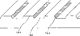
For example, the guide groove of the substrate 141 is formed as shown in fig. 11. Magneto-optical information is recorded in the wide width portion in fig. 11, i.e., on the lands (lands) 151 and grooves 152, and the magnetic layer superposed in the wall surface portions 153 becomes the target of heat treatment (annealing treatment). By the heat treatment, the magnetic layer portion as a processing target is unmagnetized or becomes an in-plane magnetic film.
The land indicates a portion on the far side of the surface (e.g., the lower surface in fig. 11) to which the laser beam for recording/reproduction is input. The portion proximal to this surface is called the groove. The laser beam for heat treatment is irradiated from the surface (e.g., the top surface of fig. 11) opposite to the side of the laser beam for recording/reproducing.
Since the region between the tracks is heat-treated, the wall surface portions 153 are heat-treated in the case of recording onto both lands and grooves. However, in the case of recording data onto one of the lands and the grooves, the other is heat-treated.
Signal replication according to the DWDD system will now be described with reference to fig. 12A to 12E. Fig. 12A shows an example of a cross-sectional view of a magneto-optical information recording medium of a DWDD system for reproduction. The medium is shown inverted from the magneto-optical information recording medium 140 shown in fig. 10. In a manner similar to the magneto-optical information recording medium 140 of fig. 10, a magnetic layer including a displacement layer 160, an exchange layer 161, and a recording layer 162 is formed. In a state where the reproducing laser beam 163 is not irradiated, in each layer, an exchange coupling force (switchcoupling force) acts, and the atomic spins in each layer of the displacement layer 160 and the exchange layer 161 are oriented in the same direction as the direction of the atomic spin 164 in the recording layer 162. The domain wall 165 is formed at a boundary portion where adjacent atoms spin (the directions of atomic spins are opposite).
When the reproducing laser beam 163 is irradiated to the magneto-optical information recording medium, for example, a distribution of the temperature T of the magnetic layer as shown in fig. 12B is obtained. As shown in fig. 12A, the replication laser beam 163 is irradiated from the substrate side. Ts represents the curie temperature of the exchange layer 161. In association with such a temperature distribution, a distribution of domain wall energy density σ as shown in fig. 12C is formed. In general, since the domain wall energy density decreases with an increase in the temperature of the magnetic layer, a distribution is obtained in which the density becomes the lowest at the position of the highest temperature shown in fig. 12B. Thus, the domain wall driving force f (x) moves the domain wall 165 in the direction of low domain wall energy density, i.e., in the high temperature direction of the magnetic layer. The distribution of domain wall driving forces f (x) is shown in fig. 12D.
When there is a gradient (variation) in the energy density of the domain wall as described above, a domain wall driving force f (x) represented by the following equation (1) acts on the domain wall of each layer.
F(x)=-*σ/*x …(1)
The domain wall driving force f (x) acts to move the domain wall 165 in the direction of low domain wall energy density. That is, at a position where the temperature of the magnetic layer is lower than the curie temperature Ts of the exchange layer, even if domain wall driving forces f (x) due to such a temperature gradient act, since the layers are exchange-coupled with each other, movement of the domain wall does not occur because it is hindered by the coercivity of the large domain wall of the recording layer. However, at a position where the temperature of the magnetic layer is higher than the curie temperature Ts of the exchange layer, since the exchange coupling between the displacement layer 160 and the recording layer 162 is cut off, the domain wall of the displacement layer 160 whose domain wall coercivity is small can be moved by the domain wall driving force f (x) according to the temperature gradient. Therefore, when the reproducing laser beam 163 is irradiated while scanning the magneto-optical information recording medium, the domain wall of the displacement layer 160 moves toward the high temperature side (the direction indicated by the arrow 166 in fig. 12A) at the position where the domain wall exceeds the curie temperature Ts and enters the coupling exchange region.
By the principle as described above, the domain wall formed on the magneto-optical information recording medium at intervals corresponding to the recording signal moves at each scanning performed by the laser beam. Therefore, the size of the magnetic domain for effective recording is enlarged at the time of reproduction, the reproduction carrier signal can be increased, and reproduction exceeding the optical limit can be performed. The waveform shown in fig. 12E relates to an example of a replica waveform obtained from the magnetic layer in fig. 12A. In this case, when the atomic spins in the recording layer 162 are oriented downward, a signal at a low level is obtained.
Equation (1) indicating the domain wall driving force f (x) in the reproduction by DWDD system essentially derives from equation (2) below.
F(x)=2M(x)·Hd(x)+2M(x)·Ha-σ(x)/x-*σ/*x …(2)
Wherein,
m (x): magnetization of displacement layer 160
Hd (x): demagnetizing field
Ha: external magnetic field, e.g. leakage flux from the recording layer 162
σ (x): wall energy per unit area
For example, as disclosed in "Journal of Magnetic Society of Japan", Vol.22, supplement No.S2, 1998, pp.47-50, by extremely reducing the magnetization of the displacement layer 160, the first term (2M (x) · Hd (x)) and the second term (2M (x) · Ha) on the right side of equation (2) can be ignored. Further, if the device is constructed such that non-closed magnetic domains are formed by converting them into in-plane magnetic films, for example, by magnetizing both sides of the recording tracks (guide grooves) or by heat-treating them, the third term (- σ (x)/x) on the right side of equation (2) can also be ignored. Thus, by significantly reducing the magnetization of the displacement layer 160 and converting it into an in-plane magnetic film by either side of the non-magnetized tracks or by heat treating them, the right side of equation (2) can be composed of the fourth term only and is equal to equation (1), enabling a copy by a DWDD system to be performed.
Therefore, in order to realize the above system, the process of converting both sides of the non-magnetized recording tracks into in-plane magnetic films by heat-treating them or the like is a very important process. By the heat treatment, the magnetic anisotropy of the heated portion is weakened and the magnetic coupling is weakened. In the heat treatment (also referred to as initialization or annealing treatment), since the track density can be increased by heat-treating a narrow region between tracks, a light spot smaller than that used for recording/reproducing of the magneto-optical information recording medium is generally used. That is, the apparatus for performing the heat treatment is generally prepared separately from the apparatus for performing the recording/reproducing.
However, in the above magneto-optical information recording medium, even if the heat treatment is performed, the change in the magnetic property occurs only in the treatment target portion, and there is no method of determining or checking whether the heat treatment has been performed appropriately. On the other hand, if the width of the heat treatment (heat treatment power) is too small, an appropriate recording power margin (margin) cannot be secured although the recording performance of the track is improved. If the width is too large, the recording performance of the track deteriorates.
It is therefore an object of the present invention to provide a heat treatment determination method and a heat treatment determination apparatus for a magneto-optical information recording medium, in which it can be easily determined whether or not heat treatment has been properly performed, in other words, whether or not heat treatment has been performed (with an appropriate power) for an appropriate width.
Detailed Description
According to the present invention, in order to determine whether or not heat treatment in a magneto-optical disk has been appropriately performed, a heat treatment target portion in which magnetization is changed by the heat treatment is read by a laser pickup (pick up), thereby detecting a magneto-optical signal (MO signal) in this portion. At this time, it is desirable that the correct modulation signal has been recorded in the portion to be heat-treated, or that such a portion has been magnetized in one direction.
First, a first embodiment of a heat treatment determination device for determining whether or not heat treatment (annealing treatment) of a magnetic layer between tracks of a magneto-optical information recording medium constructed as described above has been appropriately performed will be described with reference to fig. 1. The heat treatment determination device of this embodiment performs the normal heat treatment and determines whether or not the heat treatment has been performed appropriately by detecting the magneto-optical signal of the heat-treated portion. A series of constituent elements including the LD11, the collimator 12, the servo circuit 17, and the like, which will be described later, correspond to a heat treatment device that performs a conventional heat treatment and an irradiation device that irradiates a laser beam for detecting the level of a magneto-optical signal. The photodetectors 24, 26 and the differential detecting circuit 27 (and the power monitor 40), which will be described later, correspond to detection means for detecting the level of the magneto-optical signal. The controller 28 corresponds to determination means for determining whether the heat treatment is appropriate or inappropriate on the basis of the level of the detected magneto-optical signal. The controller 28 controls the operations of the other components of the heat treatment determining apparatus 10.
The heat treatment determining apparatus 10 of the present embodiment uses a Laser Diode (LD)11 that oscillates a laser light having a wavelength equal to about 400nm as a light source and uses an objective lens 16 having a numerical aperture equal to 0.85. The above components are merely examples of the present invention, and other various light sources, lenses, and the like may be used for the heat treatment determining device 10.
The laser beam (light beam) oscillated from the LD11 is converted into parallel light by a collimator (collimator lens) 12, then passes through a shaping prism 13, and is divided into three laser beams, i.e., one 0 th order diffracted light and two first order diffracted lights, by a diffraction grating 14. These laser beams are split by the beam splitter 15 into, for example, light directed to a power monitor 31 including a photodiode and light directed to a magneto-optical disk 33. The detection result of the power monitor 31 is transmitted to an APC (automatic power control) 30, and the APC 30 controls the laser driver 29 so as to control the output of the LD 11.
The three laser beams directed to the magneto-optical disk 33 are converged by the objective lens 16 and irradiated onto the magneto-optical disk 33. For example, the 0 th order diffracted laser beam 35 is a laser beam used for heat treatment or heat treatment judgment. The first order diffracted laser beams 34 and 36 are laser beams for tracking (tracking). The three laser beams 34 to 36 are reflected by the magneto-optical disk 33 and enter the photodetector 20 through the beam splitter 15. The light detector 20 has a light detector for servo (servo). The reflected light of each of the laser beams 34 and 36 is detected by a photodetector for servo to perform tracking servo. The reflected light of the laser beam 35 is detected by a detector for servo to perform focus servo. Although not shown, the optical head including the objective lens 16 may be moved in the radial direction of the magneto-optical disk 33 by an optical head (optical head) transfer mechanism. Further, the controller 28 transmits a control signal to a spindle (spindle) driver 32 and controls the rotation of the magneto-optical disk 33.
The laser beam from the LD11 is controlled by focus servo and tracking servo actuation so that the focal point is focused on the magneto-optical disk 33 and a predetermined position is tracked. The focus servo control and the tracking servo control are realized by the servo circuit 17.
The reflected light of the laser beam 35 is split by the beam splitter 18 into light directed to the λ/2 plate 21 and further into light directed to the photo detector 24 and light directed to the photo detector 26, respectively. In the present embodiment, for example, a P wave is input to the photodetector 24 and an S wave is input to the photodetector 26. There is a property that, when the laser beam 35 is reflected by the magnetized surface of the magneto-optical disk 33, the polarization plane of the reflected light is rotated in accordance with the magnetic field. This property is known as the kerr effect.
As will be explained later, when the heat treatment power is increased, the magneto-optical signal obtained from the reflected light from the portion having undergone the heat treatment gradually changes. According to the present invention, attention is paid to such a property that a magneto-optical signal in a portion which has been subjected to heat treatment is detected from a P-wave and an S-wave, and the magnitude of the heat treatment power is determined, that is, whether the heat treatment is appropriate or inappropriate is determined based on the detection result.
Although the present embodiment is made on the assumption that the magnetization direction is deviated to a predetermined direction at the time of forming a magneto-optical film of a magneto-optical disk, it may be also configured in such a manner that a heat treatment target portion is preliminarily magnetized in one direction, for example, by a laser beam 38 and a magnetic head 39 shown in fig. 1, before the heat treatment. With this configuration, the above determination can be easily made. Instead of magnetization, if a modulation signal is recorded in advance in the heat treatment target portion and the amplitude of the magneto-optical signal is detected from the reflected light, the signal amount increases to twice as much as in the case where magnetization is performed. Therefore, the above determination can be more easily performed.
The uniform magnetization of a magneto-optical disk or the recording of a modulated signal can be performed simultaneously. That is, a uniform magnetic field or a modulated magnetic field is applied while the laser beam is being tracked for heat treatment. For example, an objective lens having a magnetic coil is used as a means for generating a magnetic field for recording. In the present invention, for example, since a high frequency is unnecessary as a modulation signal, the magnetic head 37 arranged on the substrate side may be used. Further, in the case of performing uniform magnetization, a permanent magnet may be used.
Since the above-described recording of the uniform magnetization or the modulation signal cannot be performed after the heat treatment is performed, a determination as to whether the heat treatment is appropriate or inappropriate can be made using such a principle. That is, after the heat treatment is performed, for the portion where the heat treatment is performed, the uniform magnetization or the recording of the modulation signal is performed by the laser beam 38 and the magnetic head 39 with a smaller power suitable for performing the heat treatment. After that, the replica signal, that is, the magneto-optical signal of the portion is detected by the above-mentioned photodetectors 24, 26 and the differential detection circuit 27. If the heat treatment has been properly performed, a magneto-optical signal corresponding to such a state is obtained since recording of the portion cannot be performed. On the other hand, if the heat treatment is improperly performed for some reason, a magneto-optical signal at a level corresponding to such a state is obtained.
The amounts of reflected light detected by the photodetectors 24 and 26 are input to a differential detection circuit 27. In the differential detection circuit 27, if only the P-wave or the S-wave is used, the difference in amplitude (amplitude) is small. Therefore, the amplitude is doubled by superimposing these two signals, thereby improving the detection accuracy of the magneto-optical signal. Since the same noise is generated in both the P-wave and the S-wave, the noise can also be eliminated by using both signals.
The magneto-optical signal detected by the differential detection circuit 27 is transmitted to the power monitor 40. For example, the power monitor 40 converts the detection result into a digital signal and transmits it to the controller 28. The power monitor 40 displays the value of the digital magneto-optical signal on a display or the like, if necessary.
From the received detection results, the controller 28 determines whether or not it is an appropriate magneto-optical signal (amplitude). The detection result may be used for feedback control of the heat treatment power so that constant and appropriate heat treatment is continuously performed. The control of the heat treatment power is performed by, for example, a method of sending a predetermined command from the controller 28 to the laser driver 29 and controlling the output of the LD 11. When the received magneto-optical signal does not have an appropriate value, the controller 28 can display a warning indicating this fact or stop the processing of the magneto-optical disk.
In the present embodiment, a push-pull method (push-pull method) is used for the tracking servo. That is, control is made in such a manner that two tracking laser beams (34, 36) are respectively irradiated onto the recording/reproducing tracks (lands 151, grooves 152) adjacent to the wall surface portions 153 in fig. 11 serving as a heat treatment target or a heat treatment judgment, and the laser beam 35 is certainly irradiated onto the wall surface portions 153 by calculating the reflected light amount. The area of the spot of the laser beam 35 on the magneto-optical disk 33 is generally smaller than the area of the spot of each of the laser beams (34, 36).
As described above, since the laser beam for determining whether or not the heat treatment has been appropriately performed also traces the same wall surface portion 153 as that for the heat treatment, it is possible to use as the tracing means a device similar to that for performing only the heat treatment of the magneto-optical disk. For example, the method for use in the optical disk heat treatment apparatus disclosed in JP-A-2002-319201 can be applied.
In the above optical disc heat treatment apparatus, the laser beam is divided into three kinds of laser beams, for example, a laser beam for heat treatment and two laser beams for tracking, by a diffraction grating or the like, and tracking for heat treatment is realized by a sampling servo system using wobble pits (wobbble pits). In this embodiment, it is applied to the land/groove substrate so as to be realized by a push-pull system. That is, as described above, one of the tracking laser beams tracks the lands 151 and the other tracks the grooves 152, thereby allowing the laser beam used for the heat treatment judgment to track the boundary portion (wall surface portion 153) between the lands 151 and the grooves 152.
As described above, the laser beam is first irradiated onto the wall surface portion 153 of the magneto-optical disk 33, so that the magnetic layer of that portion is unmagnetized or converted into an in-plane magnetic film (i.e., is heat-treated). The width to be heat-treated increases as the LD power increases.
In the present embodiment, after irradiation of at least a predetermined range of the wall surface portion 153 of the magneto-optical disk 33 with the laser beam for heat treatment is performed, the laser beam having a power smaller than that of the laser beam for heat treatment is irradiated again onto the wall surface portion 153 in this range, and the magneto-optical signal is detected from the reflected light, thereby determining whether or not the heat treatment has been performed correctly. For example, the innermost track of a magneto-optical disk is set as a test area. Heat treatment is performed in the test area, after which the magneto-optical signal is detected and it is determined whether the heat treatment has been performed properly. If it is determined that the heat treatment has been appropriately performed, the heat treatment is performed for all the remaining tracks at the heat treatment power for the heat treatment.
The process of determining the appropriate magneto-optical signal will now be described. Fig. 2 is a graph showing an example of the relationship between the thermal processing power and the magneto-optical signal. The relative speed of the magneto-optical disk with respect to the laser beam at the time of heat treatment is, for example, equal to 4 m/sec. The ordinate axis (magneto-optical signal) of the graph of fig. 2 represents the level of a magneto-optical signal (MO signal) obtained from the P-wave and S-wave of reflected light when the heat-treated wall surface portion 153 was tracked at a low laser power of 0.5mW after completion of the heat treatment. The numerical values of the ordinate axes of the graphs are shown as relative values, with predetermined values being set as references. The quality of a magneto-optical signal in the case where recording/reproducing of a magneto-optical disk has been performed is determined by the width of a beam spot in a heat treatment.
As can be understood from fig. 2, the level of the magneto-optical signal does not change much when the heat treatment power is equal to about 2 to 3 mW. However, when the thermal processing power is equal to about 3 to 6mW, the level of the magneto-optical signal decreases as the thermal processing power increases. It is desirable that the magneto-optical disk has been DC-magnetized before the heat treatment, during the heat treatment, or after the heat treatment or the modulation signal has been recorded. Therefore, the level of the magneto-optical signal after the heat treatment is changed from the level before the heat treatment and the rate of change is changed according to the heat treatment power.
Fig. 3 is a graph showing one example of the relationship between the heat-treating power and the recording power margin and the relationship between the heat-treating power and the bit error rate. The wavelength of the LD of a magneto-optical signal recording/reproducing apparatus for recording/reproducing of a magneto-optical disk is equal to 660 nm. The numerical aperture of the objective lens is equal to 0.6. In the above apparatus, a laser beam is irradiated from the substrate side. The magneto-optical disk used in this example had a groove pitch (pitch) equal to 1.08 μm and a track pitch equal to 0.54 μm.
The recording power margin means a margin of the recording power in which the bit error rate is equal to or less than a predetermined value. In association with the overwriting (overwriting) characteristic and the cross-writing (cross-writing) characteristic, the bit error rate varies according to the recording power. However, from which the bit error rate is equal to or less than a predetermined value, e.g. 10-4The recording power margin is obtained from the upper limit value, the lower limit value and the middle value of the recording power. For example, assuming that the upper limit value is 0.9, the lower limit value is 1.1, and the intermediate value is 1.0, the range satisfying the above bit error rate is a range of 10% in the direction from the intermediate value along the upper limit or the lower limit. In this case the recording power margin is equal to +/-10%. Recording power for recording magneto-optical information to magneto-optical diskAnd the power to reproduce magneto-optical information from a magneto-optical disk, which is distinguished from the power of heat treatment.
Such a recording power margin varies depending on the heat treatment power used when the heat treatment is performed. In fig. 3, the curve shown by the dotted line represents the relationship between the heat treatment power and the recording power margin. The left ordinate axis indicates the scale of the recording power margin and the unit thereof is set to (+/2)%. In this example, the recording power margin occurs in a range where the heat treatment power is equal to about 3.5 to about 6mW, and the recording power margin becomes a peak (about +/-18%) when the heat treatment power is equal to about 5 mW.
On the other hand, the curve shown by the solid line represents the relationship between the heat treatment power and the bit error rate. More specifically, it shows the bottom (minimum) of the bit error rate according to the thermal processing power. The scale of the bit error rate is set on the ordinate axis on the right side.
Such a recording power margin is often used as a reference in quality management of the manufacture of magneto-optical discs. Assume now that a value of +/-16% or more is required as the recording power margin. Therefore, it can be understood that it is necessary to set the heat treatment power to a value in the range of about 4.5 to 5.2 mW. Subsequently, referring again to fig. 2, it can be understood that the level of the magneto-optical signal corresponding to the range of the thermal processing power (i.e., 4.5 to 5.2mW) is equal to about 0.3 to 0.6.
Therefore, in this case, in the heat treatment judgment of the magneto-optical disk, the disk in which the magneto-optical signal corresponding to the reflected light is at a level of about 0.3 to 0.6 passes the inspection, otherwise the heat treatment needs to be controlled to obtain such reflected light. If the heat treatment is performed while monitoring the reflected light as described above, an error of the heat treatment step can be prevented. Since the interrelations shown in fig. 2 and 3 are affected by the precise structure of the magneto-optical disk and the like, these characteristics can also be changed in a lot (lot) unit basis (for example, 1000 magneto-optical disks) or a unit smaller than 1000.
A heat treatment determination device according to a second embodiment of the present invention will now be described with reference to fig. 4. In the heat treatment determination device of the first embodiment described above, the laser beam from the LD11 is divided into three kinds of laser beams by using the diffraction grating 14. One laser beam is used for heat treatment or detection of the amount of reflected light, and the other two laser beams are used for tracking. However, it is also possible to construct in such a manner that two LDs are prepared, one for heat treatment or detection of magneto-optical signals and the other for tracking. A series of constituent elements including the LD 61, the collimator 62, the servo circuit 67, and the like, which will be described later, correspond to a heat treatment device for performing a conventional heat treatment and an irradiation device that irradiates a laser beam for detecting the level of a magneto-optical signal. The photodetectors 74, 76 and the differential detection circuit 77 (and the power monitor 91), which will be described later, correspond to detection means for detecting the level of the magneto-optical signal. The controller 78 corresponds to determination means for determining whether the heat treatment is appropriate or inappropriate on the basis of the level of the detected magneto-optical signal as described above. The controller 78 controls the operation of the other components of the heat treatment determining device 60.
In the heat treatment determination device 60 in fig. 4, the LD 61 is a laser beam source that performs irradiation for heat treatment and detection of magneto-optical signals, and the LD 80 is a laser beam source for tracking. The laser beam from the LD 61 is irradiated onto a magneto-optical disk 86 (laser beam 87) through a collimator 62, a shaping prism 63, beam splitters 64 and 65, and an objective lens 66. The reflected light of the laser beam 87 irradiated in this manner is detected by the photodetectors 74 and 76. In a similar manner to the photodetectors 24 and 26 described with respect to fig. 1, the photodetectors 74 and 76 detect the reflected light amounts of the P-wave and S-wave, respectively.
The detection results of the photodetectors 24 and 26 are sent to a differential detection circuit 77 where the level of the magneto-optical signal is detected. The detection result is transmitted to the power monitor 91, digital conversion of the level of the detected magneto-optical signal, etc., is performed by the power monitor 91, and the digital signal is transmitted to the controller 78. The controller 78 determines whether the heat treatment is appropriate or inappropriate on the basis of the supplied detection result, and controls the laser drivers 79 and 82, the axis driver 85, and the like in accordance with the detection result, thereby allowing the appropriate heat treatment to be performed.
The laser beam from the LD 80 is irradiated onto a magneto-optical disk 86 (laser beam 87) through a collimator 81, beam splitters 64 and 65, and an objective lens 66. The reflected light of the laser beam 87 irradiated in this way is detected by the photodetector 68 through the beam splitter 65 and the beam splitter 70. Based on the detection result, tracking control is performed by the servo circuit 67. The beam splitters 64, 65 and 72 are polarizing beam splitters.
In the heat treatment judging apparatus of the present embodiment, since it is assumed that a land/groove substrate having lands and grooves is used as the magneto-optical disk 86, a laser beam for heat treatment (for detection of magneto-optical signals) and a laser beam for tracking are separately prepared as described above. However, in the so-called groove substrate as shown in FIG. 5 or in the sampling servo substrate formed with the guide grooves as shown in FIG. 6, it is not necessary to additionally prepare a laser beam for tracking to heat-treat the land portions. The groove substrate of fig. 5 includes grooves 93 and lands 94 indicated by hatched areas, and the land 94 portions become targets for heat treatment and heat treatment judgment. The sampling servo substrate of fig. 6 is composed of grooves 95, lands 96, and pits 97 and 98. The lands 96 become targets for heat treatment and heat treatment judgment.
In the sampling servo substrate of fig. 6, tracking is performed on the land 96 portion at the time of heat treatment and heat treatment judgment. The pits 98 are tracked by a large spot of laser beam at the time of recording/reproducing, thereby allowing a tracking error signal to be generated.
A heat treatment determination device according to a third embodiment of the present invention will now be described. The heat treatment determination device of the first embodiment employs a configuration in which the power of the laser beam used for the heat treatment is reduced and the portion to be heat treated is tracked again by the reduced power, and the amount of reflected light is detected. However, the detection process can be performed by another method. For this reason, in the heat treatment determination device of the third embodiment, a second optical pickup different from the first optical pickup for heat treatment is mounted. The portion to be heat-treated is tracked by the second optical pickup at a power lower than the LD power for heat treatment, thereby determining whether or not heat treatment has been appropriately performed. With such a configuration, the first optical pickup and the second optical pickup can be made to operate in parallel, and the time of the heat treatment step including the heat treatment determination can be shortened.
In the heat treatment determination device according to the fourth embodiment of the present invention, two LDs are used for the magneto-optical disk shown in fig. 5 or 6. That is, the two LDs are arranged in such a manner that the laser beam from one of the LDs is used for both heat treatment and tracking, and the land is tracked, and after the heat treatment, the laser beam from the other LD tracks the portion (land) that is heat-treated to detect the amount of reflected light. According to this configuration, whether or not the heat treatment has been appropriately performed can be determined by the latter laser beam.
A heat treatment determination device according to a fifth embodiment of the present invention is manufactured to improve the heat treatment determination device of the first embodiment. In the first embodiment, the laser beam is divided into three kinds of laser beams by the diffraction grating 14, 0-order diffracted light is used for heat treatment, and first-order diffracted light is used for tracking. However, in the fifth embodiment, the 0 th order diffracted light is used for thermal processing and for tracking. The former first-order diffracted light is used to track the heat-treated portion tracked by the 0 th-order diffracted light, and the latter first-order diffracted light is used to detect the amount of reflected light. In order to prevent the heat treatment from being performed by the first-order diffracted light, it is desirable that the first-order diffraction spectral ratio (spectral ratio) is sufficiently small. For similar reasons, it is desirable that the spot size of the first order diffracted light is larger than the spot size of the 0 th order diffracted light.
An example of the operation of the controller 28 shown in fig. 1 or the controller 78 shown in fig. 4 will now be described with reference to the flowchart of fig. 7. Considered here is a case where the controller controls the heat treatment process and determines whether the heat treatment process has been appropriately performed. The heat treatment process and the determination process are performed in parallel. Shortly after the heat treatment is completed, the portion that has been heat-treated by the heat treatment process is judged by a judgment process. The flow chart of fig. 7 shows the decision process.
In the heat treatment process, a laser beam is irradiated onto the wall surface portion 153 of, for example, a magneto-optical disk at a heat treatment power set in advance. If the heat treatment is performed at an inappropriate heat treatment power for some reason, the determination process finds out this fact and performs a predetermined process.
The determination process of fig. 7 will be described below. First, in step S1, the controller (28, 78) controls in such a manner that a laser power of a power lower than that for heat treatment is irradiated onto a portion to be heat-treated and the level of the magneto-optical signal is detected from the amount of reflected light. The amount of reflected light is obtained by a photodetector (24, 26, 74, 76) and supplied to a differential detection circuit (27, 77) as, for example, a predetermined current value. A differential detection circuit (27, 77) detects the level of the magneto-optical signal from the amount of reflected light supplied and supplies it to a controller (28, 78) through a power monitor (40, 91). In step S2, whether the level of the detected magneto-optical signal is within an allowable range. The allowable range of magneto-optical signal levels is determined, for example, as mentioned in figures 2 and 3. That is, the heat treatment power at which the recording power margin of the predetermined value or more is obtained is derived from fig. 3. The range of the magneto-optical signal level corresponding to the heat treatment power obtained in this way is derived from fig. 2 and set as the range of the above-described magneto-optical signal level. In the example of fig. 2, it is in the range from 0.3 to 0.6. For example, this range of magneto-optical signal levels is set per manufacturing lot of magneto-optical disks, stored into a memory or the like in the controller (28, 78), and referred to in the above determination.
If it is determined in step S2 that the magneto-optical signal level is within the allowable range, it is determined in step S3 whether the determination target still exists. If there is no decision target, the process ends. If there is a determination target, the process proceeds to step S4 and determines whether the detected magneto-optical signal level is within a predetermined range narrower than the allowable range. If it is determined in step S4 that the detected magneto-optical signal level is outside the predetermined range, then step S5 follows. The setting of the heat treatment power is changed so that an optimum recording power margin can be obtained, and the changed heat treatment power is transmitted to the heat treatment processes which are operated in parallel. Steps S4 and S5 may also be omitted if it is sufficient to determine only whether the magneto-optical signal level is within the allowable range.
If it is determined in step S4 that the magneto-optical signal level is within the predetermined range, then step S6 follows and the position of the magneto-optical disk is controlled to determine the next heat-treated portion. The processing returns to step S1. In the case where the setting of the heat treatment power is changed in step S5, the processing procedure also proceeds to step S6, and thereafter returns to step S1.
If it is determined in step S2 that the detected magneto-optical signal level is outside the allowable range, step S7 is followed and information indicating this fact is displayed on a display device or the like. The heat treatment of the magneto-optical disk performed before is stopped in step S8, and the determination process is also ended. Such a procedure is adopted because it is judged that the magneto-optical disk being processed does not satisfy the required quality. Some improvements, such as resetting of heat treatment power and the like, are required with respect to the subsequent heat treatment of magneto-optical disks. In this example, when the magneto-optical signal level is outside the allowable range, the heat treatment process and the determination process are stopped as described above. However, another countermeasure method may also be used.
The operation of the controller as described above can be realized by the control of the microcomputer, the control of the CPU based on the command of the program loaded in the memory, and the like.
The positional relationship of the spots of the laser beam irradiated onto the magneto-optical disk will now be described with reference to fig. 8A, 8B, 9A, and 9B. Fig. 8A shows an example of the layout of light spots in the case where the heat treatment determining apparatus according to the first embodiment is used. According to the configuration of a magneto-optical disk shown in the drawing, which is a land/groove substrate similar to that of fig. 11, it is constituted by lands 151, grooves 152 and wall surface portions 153. The spots 100, 101 and 102 of the laser beams correspond to the spots of the three laser beams 34, 35 and 36, respectively, shown in fig. 3. The spot 101 corresponds to the spot of the 0 th order diffracted laser beam 35, and the heat treatment or the heat treatment determination is performed by irradiation of such laser beam. Spots 100 and 102 correspond to spots of first order diffracted laser beams 34 and 36 and track lands 151 and grooves 152, respectively, so that they are used for tracking servo. As is apparent from the figure, in the present example, the area of the spot 101 on the medium (magneto-optical disk) is smaller than the area of each of the spots 100 and 102 on the medium.
Fig. 8B shows an example of the layout of light spots in the case where the heat treatment determining apparatus according to the second embodiment is used. According to the configuration of the magneto-optical disk shown in the figure, it is a land/groove substrate similar to that of FIG. 11. Spots 110 and 111 of the laser beam correspond to the spots of laser beam 87 in fig. 4. The spot 110 is a spot of the laser beam irradiated from the LD 61 and is used for heat treatment or heat treatment determination. The spot 111 is a spot of the laser beam irradiated from the LD 80 and is used for tracking servo.
Fig. 9A shows an example of a layout of spots of a laser beam irradiated onto the groove substrate or the sampling servo substrate shown in fig. 5 or 6. The spot 120 is a spot of a laser beam for heat treatment. The spot 121 is a spot of a laser beam used for heat treatment determination. In this example, the spots are irradiated from different LDs. It is also possible to divide the laser beam from one LD into three laser beams by a diffraction grating and allocate two of them as laser beam spots for heat treatment or heat treatment determination, respectively. In this example, spots 120 and 121 have nearly the same diameter.
Fig. 9B shows an example of irradiating nine laser beams onto the land/groove substrate by using two diffraction gratings. The apparatus is configured in such a manner that the laser beams of the spots 130B and 132B are used for tracking, the laser beam of the spot 131B is used for heat treatment, and the laser beam of the spot 131A is used for heat treatment determination.
It is also possible to control in such a manner that the area of the spot of the laser beam for heat treatment on the medium is smaller than the area of the spot of the laser beam for detecting the magneto-optical signal of the region to be heat-treated.
As is apparent from the above description, many of the components for determining whether the heat treatment is appropriate or inappropriate are common to the components for heat treatment. Therefore, each of the above embodiments may also be configured to realize the determination process by a conventional heat treatment apparatus. However, the detection process is not necessarily limited to such a configuration. For example, the present invention may be configured as a monitoring device for measuring and displaying a magneto-optical signal level of a magneto-optical disk, or as a dedicated heat treatment determination device for determining whether or not heat treatment of the magneto-optical disk has been appropriately performed as needed.