CN1806741A - Vertical electric dust collector - Google Patents
Vertical electric dust collector Download PDFInfo
- Publication number
- CN1806741A CN1806741A CN 200510132939 CN200510132939A CN1806741A CN 1806741 A CN1806741 A CN 1806741A CN 200510132939 CN200510132939 CN 200510132939 CN 200510132939 A CN200510132939 A CN 200510132939A CN 1806741 A CN1806741 A CN 1806741A
- Authority
- CN
- China
- Prior art keywords
- suction pipe
- vacuum cleaner
- suction
- extended
- mentioned
- Prior art date
- Legal status (The legal status is an assumption and is not a legal conclusion. Google has not performed a legal analysis and makes no representation as to the accuracy of the status listed.)
- Granted
Links
Images


Landscapes
- Electric Vacuum Cleaner (AREA)
- Nozzles For Electric Vacuum Cleaners (AREA)
- Electric Suction Cleaners (AREA)
- Cleaning In General (AREA)
Abstract
本发明的目的在于提供一种延长吸入管的装入简单,在地面的扫除中能够进行即刻使用延长吸入管的扫除的立式电动吸尘器。本发明的立式电动吸尘器具有:具有电动鼓风机和集尘机构的吸尘器主体;设置在吸尘器主体下部的吸入体;设置在吸尘器主体上部的手柄;以及设置在从吸尘器主体伸出的吸入软管的前端,并且伸缩自如的延长吸入管,其特征在于:将装卸自如地收放延长吸入管的前端侧的收放筒部设置在吸尘器主体上。

An object of the present invention is to provide an upright electric vacuum cleaner which can be easily installed with an extended suction pipe, and can be cleaned immediately using the extended suction pipe during floor cleaning. The vertical electric vacuum cleaner of the present invention has: a vacuum cleaner main body with an electric blower and a dust collection mechanism; a suction body arranged at the lower part of the vacuum cleaner main body; a handle arranged at the upper part of the vacuum cleaner main body; The front end and the extended suction pipe that can be retracted freely are characterized in that a retractable cylindrical portion on the front end side of the extended suction pipe that can be detachably stored is provided on the main body of the vacuum cleaner.
Description
技术领域technical field
本发明涉及立式电动吸尘器。The invention relates to an upright electric vacuum cleaner.
背景技术Background technique
例如,特开2000-157450公开公报(特许文献1)所示的立式电动吸尘器。For example, there is an upright electric vacuum cleaner disclosed in Japanese Unexamined Patent Application Publication No. 2000-157450 (Patent Document 1).
这种电动吸尘器除了地面用吸口体之外具备吸入软管。在吸入软管的前端替换安装各种吸口,以便扫除地面以外的场所。为扫除天花板等高处,具备延长吸入管。This type of electric vacuum cleaner is provided with a suction hose in addition to the floor suction body. Replace and install various suction ports on the front end of the suction hose to sweep places other than the ground. In order to sweep high places such as ceilings, it is equipped with an extended suction pipe.
具备延长吸入管的立式电动吸尘器的延长吸入管的装入很麻烦。另外,有时使用立式电动吸尘器在地面的扫除中还有使用延长吸入管的扫除,存在不能即刻使用延长吸入管的不良情况。The installation of the extension suction pipe of the upright electric vacuum cleaner equipped with the extension suction pipe is troublesome. In addition, the upright electric vacuum cleaner may also be used to sweep the floor while cleaning using the extended suction pipe, and there is a disadvantage that the extended suction pipe cannot be used immediately.
发明内容Contents of the invention
本发明的目的是应对上述问题,提供一种延长吸入管的装入简单,在地面的扫除中能够即刻进行使用延长吸入管的扫除的立式电动吸尘器。It is an object of the present invention to solve the above problems and provide an upright electric vacuum cleaner in which the installation of the extended suction pipe is simple, and sweeping with the extended suction pipe can be performed immediately during floor cleaning.
本发明提供一种立式电动吸尘器,具有:具有电动鼓风机和集尘机构的吸尘器主体;设置在吸尘器主体的下部的吸入体;设置在吸尘器主体的上部的手柄;以及设置在从吸尘器主体伸出的吸入软管的前端,并且伸缩自如的延长吸入管,其特征在于,将装卸自如地收放延长吸入管的前端侧的收放筒部设置在吸尘器主体上。The invention provides a vertical electric vacuum cleaner, which has: a vacuum cleaner main body with an electric blower and a dust collection mechanism; a suction body arranged at the lower part of the vacuum cleaner main body; a handle arranged at the upper part of the vacuum cleaner main body; The front end of the suction hose, and the extended suction pipe that can be retracted freely, is characterized in that a retractable cylindrical portion that can detachably store the front end side of the extended suction pipe is provided on the main body of the vacuum cleaner.
根据本发明,通过将延长吸入管的前端侧插入收放筒部中,能够收放延长吸入管,通过从收放筒部取出延长吸入管能够即刻进行使用延长吸入管的扫除。According to the present invention, the extended suction tube can be stored by inserting the front end side of the extended suction tube into the retractable tube, and cleaning using the extended suction tube can be performed immediately by taking out the extended suction tube from the retractable tube.
附图说明Description of drawings
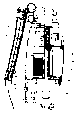
图1是涉及本发明实施例的电动吸尘器的纵剖视图。Fig. 1 is a longitudinal sectional view of an electric vacuum cleaner according to an embodiment of the present invention.
图2是涉及本发明实施例的电动吸尘器主体的纵剖视图。Fig. 2 is a longitudinal sectional view of a main body of an electric vacuum cleaner according to an embodiment of the present invention.
图3是涉及本发明实施例的电动吸尘器的分解立体图。Fig. 3 is an exploded perspective view of the electric vacuum cleaner according to the embodiment of the present invention.
图4是涉及本发明实施例的,表示竖立放置电动吸尘器状态的图。Fig. 4 is a diagram showing a state where the electric vacuum cleaner is placed upright according to the embodiment of the present invention.
图5是涉及本发明实施例的,表示使用延长吸入管扫除时形态的图。Fig. 5 is a diagram showing the state of sweeping with the extended suction pipe according to the embodiment of the present invention.
图6是涉及本发明实施例的,用吸入体扫除地面时形态的图。Fig. 6 is a view showing the state of sweeping the floor with the suction body according to the embodiment of the present invention.
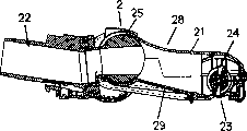
图7是涉及本发明实施例的,表示吸入体的吸口体部和尘埃通气连接管部几乎弯折成直角状态的图。Fig. 7 is a diagram showing a state in which the mouthpiece body of the suction body and the dust ventilation connection pipe are bent almost at right angles, relating to an embodiment of the present invention.
图8是涉及本发明实施例的,表示吸入体的吸口体部和尘埃通气连接管部几乎呈笔直状态的图。Fig. 8 is a diagram showing an almost straight state of the suction port body and the dust ventilation connecting pipe of the suction body according to the embodiment of the present invention.
图9是涉及本发明实施例的,表示卸下吸入体的上罩从上方俯视吸入体时的图。Fig. 9 is a diagram showing a top view of the inhalation body from above with the upper cover of the inhalation body removed, relating to the embodiment of the present invention.
图10是涉及本发明实施例的,放大表示图9的(I)部的图。Fig. 10 is an enlarged view showing part (I) of Fig. 9 according to an embodiment of the present invention.
图11是涉及本发明实施例的,图10的A-A剖视图。Fig. 11 is a sectional view of A-A of Fig. 10 related to the embodiment of the present invention.
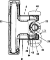
图12是涉及本发明实施例的,表示从吸入体至尘埃罩的尘埃流通路径和从延长吸入管至尘埃罩的尘埃流通路径的图。Fig. 12 is a diagram showing the dust flow path from the suction body to the dust cover and the dust flow path from the extended suction pipe to the dust cover, according to an embodiment of the present invention.
图13是涉及本发明实施例的,从正面看到的收放在吸尘器主体的尘埃罩收放部的尘埃罩的图。Fig. 13 is a view of the dust cover housed in the dust cover storage part of the main body of the vacuum cleaner seen from the front according to the embodiment of the present invention.
图14是涉及本发明实施例的,收放尘埃罩的吸尘器主体的侧视图。Fig. 14 is a side view of the main body of the vacuum cleaner with the dust cover retractable according to the embodiment of the present invention.
图15是涉及本发明实施例的,图13的B-B剖视图。Fig. 15 is a B-B sectional view of Fig. 13 related to an embodiment of the present invention.
图16是涉及本发明实施例的,从正面看到的从吸尘器主体的尘埃罩收放部取出尘埃罩时的图。Fig. 16 is a view when the dust cover is taken out from the dust cover storage part of the vacuum cleaner main body seen from the front according to the embodiment of the present invention.
图17是涉及本发明实施例的,从侧面看到的从吸尘器主体的尘埃罩收放部取出尘埃罩时的图。Fig. 17 is a side view of the embodiment of the present invention when the dust cover is taken out from the dust cover storage part of the main body of the vacuum cleaner.
图18是涉及本发明实施例的,图16的C-C剖视图。Fig. 18 is a sectional view of C-C of Fig. 16 related to the embodiment of the present invention.
图19是涉及本发明实施例的,从表面(正面)看到的尘埃罩的图。Fig. 19 is a diagram of a dust cover seen from the surface (front) related to an embodiment of the present invention.
图20是涉及本发明实施例的,图19的D-D剖视图。Fig. 20 is a D-D sectional view of Fig. 19 related to an embodiment of the present invention.
图21是涉及本发明实施例的,从后面看到的尘埃罩的图。Fig. 21 is a view of a dust cover seen from behind, relating to an embodiment of the present invention.
图22是涉及本发明实施例的,从上面看到的尘埃通气内部导管的图。Figure 22 is a view of the dust ventilation inner duct seen from above, relating to an embodiment of the present invention.
图23是涉及本发明实施例的,图22的E-E剖视图。Fig. 23 is an E-E sectional view of Fig. 22 related to an embodiment of the present invention.
图24是涉及本发明实施例的,放大表示图23的(II)部的图。Fig. 24 is an enlarged view showing part (II) of Fig. 23 according to an embodiment of the present invention.
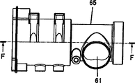
图25是涉及本发明实施例的,从分支口看到的连接座的图。Fig. 25 is a view of the connection seat seen from the branch port related to the embodiment of the present invention.
图26是涉及本发明实施例的,图25的F-F剖视图。Fig. 26 is a sectional view of F-F of Fig. 25 related to the embodiment of the present invention.
图27是涉及本发明实施例的,表示将功率测定用的管插入连接座时的图。Fig. 27 is a diagram showing a case where a tube for power measurement is inserted into a connection socket according to an embodiment of the present invention.
图28是涉及本发明实施例的,从内侧看到的下侧的主体罩的图。Fig. 28 is a diagram of the lower main body cover seen from the inside according to the embodiment of the present invention.
图29是涉及本发明实施例的,图28的G-G剖视图。Fig. 29 is a G-G sectional view of Fig. 28 related to an embodiment of the present invention.
图30是涉及本发明实施例的,放大表示图29的(III)部的图。Fig. 30 is an enlarged view showing part (III) of Fig. 29 according to an embodiment of the present invention.
图31是涉及本发明实施例的,表示将延长吸入管插入收放筒部时的图。Fig. 31 is a diagram showing the case where the extended suction tube is inserted into the retractable cylinder according to the embodiment of the present invention.
图32是涉及本发明实施例的,表示将延长吸入管插到收放筒部后(设定完了时)的图。Fig. 32 is a diagram showing the extension suction pipe inserted into the retractable cylinder (when the setting is completed) according to the embodiment of the present invention.
图33是涉及本发明实施例的,表示伸长了延长吸入管状态的图。Fig. 33 is a diagram showing a state in which the extension suction tube is extended according to the embodiment of the present invention.
图34是涉及本发明实施例的,表示缩短了延长吸入管状态的图。Fig. 34 is a diagram showing a shortened and extended suction pipe according to an embodiment of the present invention.
图35是涉及本发明实施例的,图34的H-H剖视图。Fig. 35 is a sectional view taken along line H-H of Fig. 34 related to the embodiment of the present invention.
图36是涉及本发明实施例的,解除延长吸入管具备的吸入管闭锁机构的闭锁状态的图。Fig. 36 is a diagram showing the unlocked state of the suction pipe lock mechanism included in the extension suction pipe according to the embodiment of the present invention.
图37是涉及本发明实施例的,图36的I-I剖视图。Fig. 37 is an I-I sectional view of Fig. 36 related to an embodiment of the present invention.
图38是涉及本发明实施例的,表示延长吸入管的前端侧的图。Fig. 38 is a diagram showing the front end side of the extended suction pipe according to the embodiment of the present invention.
图39是涉及本发明实施例的,图38的J-J剖视图。Fig. 39 is a J-J sectional view of Fig. 38 related to the embodiment of the present invention.
图40是涉及本发明实施例的,表示延长吸入管的前端侧的其他图。Fig. 40 is another view showing the front end side of the extended suction pipe according to the embodiment of the present invention.
图41是涉及本发明实施例的,图40的K-K剖视图。Fig. 41 is a K-K sectional view of Fig. 40 related to the embodiment of the present invention.
图42是涉及本发明实施例的,表示延长吸入管前端侧的替换吸口的图。Fig. 42 is a diagram showing an alternative suction port on the front end side of the extended suction pipe according to the embodiment of the present invention.
图43是涉及本发明实施例的,表示将延长吸入管的替换吸口替换为刷子侧时的图。Fig. 43 is a diagram showing an example of the present invention when the replacement suction port of the extended suction pipe is replaced with the brush side.
图中:In the picture:
48…电动鼓风机、26…尘埃罩(集尘机构)、1…吸尘器主体、2…吸入体、3…手柄、7…吸入软管、6…延长吸入管、9…收放筒部。48...electric blower, 26...dust cover (dust collection mechanism), 1...vacuum cleaner main body, 2...suction body, 3...handle, 7...suction hose, 6...extended suction pipe, 9...retractable cylinder.
具体实施方式Detailed ways
以下,参照附图说明涉及发明实施方式的实施例。Hereinafter, examples related to embodiments of the invention will be described with reference to the drawings.
首先,结合图1~图8叙述。First, it will be described with reference to FIGS. 1 to 8 .
电动吸尘器具有:吸尘器主体1;装卸自如地安装在吸尘器主体1下部的吸入体2;以及于吸尘器主体1上部折叠自如的手柄3。The electric vacuum cleaner has: a vacuum cleaner
手柄3转动自如地被支撑在吸尘器主体1的手柄支撑轴4上,通常如图6所示,竖起手柄3进行地面的扫除。手柄3具有夹子5,利用夹子5能够约束手柄3的竖立状态,因此在扫除中不会发生手柄3折叠的情况。收放时,如图1、图2所示折叠收放手柄3。The
如图6所示,在地面的扫除中使用吸入体2。在图5所示的高处、沙发上、角落等的扫除中使用延长吸入管6。As shown in FIG. 6, the
延长吸入管6设置在从吸尘器主体1伸出的柔性吸入软管7的前端,自如伸缩。在高处拉出延长吸入管6进行扫除。在窄处能够缩短延长吸入管6使用。由于是对应使用场所的使用方法,因此使用方便性良好。The
如图4、图5所示,吸入软管7滑动自如地被支撑在设置在吸尘器主体1上的软管导环8上。延长吸入管6装卸自如地插入安装在设置在吸尘器主体1上的收放筒部9内。吸尘器主体1上手柄3的安根底附近设置C形状的软管接收部20。As shown in FIGS. 4 and 5 , the
使用延长吸入管6扫除时,从软管接收部20取出吸入软管7,拉出地拉长于软管导环8中滑动自如的吸入软管7进行扫除。也能进行高处的扫除。When using the extended
收放时,将收缩成很短的吸入软管7嵌入保持在软管接收部20内,将延长吸入管6插入到收放筒部9内。由此,将吸入软管7以及延长吸入管6贴近吸尘器主体1地收放不会晃荡,因此容易收放。When retracting, the
如图7、图8所示,吸入体2具有吸口体部21和连接吸尘器主体1的尘埃通气连接管部22。As shown in FIG. 7 and FIG. 8 , the
吸口体部21具有吸入口23,吸入口23设有扫起尘埃的转动刷子24。利用转动自如的转动结合部25结合吸口体部21和尘埃通气连接管部22。吸口体部21和尘埃通气连接管部22以转动结合部25为支点,能够如图7所示几乎弯折成直角或如图8所示转动到呈笔直延伸状态。The
利用转动结合部25的通道,连通吸口体部21的吸入口23和尘埃通气连接管部22的内部。转动结合部25还具备作为吸入口用闸门的功能。转动结合部25通过如图7所示几乎弯折呈直角吸入口用闸门能够关闭,遮断转动结合部25通道。由此,能够阻断吸口体部21和尘埃通气连接管部22的连通。Utilize the channel of the rotating
通过如图8所示转动到呈笔直延伸的状态,吸入口用闸门能够打开,保证吸口体部21和尘埃通气连接管部22的连通。在如图8所示的几乎呈笔直地延长吸入管2的状态下,进行使用吸入体2的扫除。As shown in FIG. 8 , the valve for the suction port can be opened to ensure the communication between the suction
如图7所示几乎弯折呈直角时,关闭转动结合部25的吸入口用闸门因此不能进行使用吸入体2的扫除。取代之,进行使用延长吸入管6的扫除。即使在如图8所示打开转动结合部25的吸入口用闸门的状态下,也可以使用延长吸入管6进行扫除,但由于吸入体2和延长吸入管6一同进行吸入会导致双方的吸力下降,因此不建议使用。When bent almost at right angles as shown in FIG. 7 , the suction gate of the swivel joint 25 is closed, so cleaning using the
图12是便于理解表示从吸入体2至尘埃罩26的尘埃流通路径和从延长吸入管6至尘埃罩26的尘埃流通路径的图。如该图中可理解的那样,利用尘埃通气内部导管27将吸入体2连通到尘埃罩26上。另外,将延长吸入管6从尘埃通气内部导管27的途中连通到尘埃罩26上。FIG. 12 is a diagram illustrating the dust flow path from the
如此地,利用尘埃通气内部导管27尘埃罩26可以分支地连通吸入体2和延长吸入管6,因此打开转动结合部25的吸入口用闸门时,关闭延长吸入管6进行利用吸入体2的扫除。关闭转动结合部25的吸入口用闸门时,进行利用延长吸入管6的扫除。In this way, the
如此地,通过将吸入体2弯折成直角(竖起吸尘器主体1),或呈笔直(放倒吸尘器主体1),便于交替进行利用吸入体2的扫除和利用延长吸入管6的扫除。可提供使用方便性良好的吸尘器。In this way, by bending the
结合图9、图10、图11叙述有关转动抑制机构。In conjunction with Fig. 9, Fig. 10 and Fig. 11, the relevant rotation restraining mechanism is described.
如上所述,竖起吸尘器主体1或放倒吸尘器主体1地使用该电动吸尘器。为此,具备切实保持竖起吸尘器主体1的状态并能够简单地转动到放倒状态的转动抑制机构。吸入体2具备该转动抑制机构。As described above, the electric vacuum cleaner is used with the vacuum cleaner
如图7、图8所示吸入体2的吸口体部21具有上罩28和下罩29。在图9、图10、图11的图示中,取下上罩28,表示下罩29的内部。As shown in FIGS. 7 and 8 , the
吸入体2的吸口体部21在吸口体23的后侧隔开间隔具有大后轮40。吸入口体23的前侧下部具有小前轮41。转动结合部25的轴心位于后轮40的转动轴心附近地进行设置。用前后4个轮支撑吸入体2,因此在竖起吸尘器主体1的状态下能够自立。The
吸入口体21的下罩29上设有邻接转动结合部25的板簧42。板簧42在中央具有沿纵向延长的隆起部43。构成转动结合部25的尘埃通气连接管部22的转动轴44上设有突起44。利用该突起45和板簧42的隆起部43能够形成转动抑制机构。The
突起45和隆起部43彼此相对地设置并且突起45滑动于板簧42地设置该转动抑制机构。通过相对吸口体部21转动尘埃通气连接管部22,尘埃通气连接管部22的突起45碰到板簧42的隆起部43。还有,若再用力转动尘埃通气连接管部22,则板簧42弯曲,隆起部43避让后退,因此突起45超过隆起部43的顶部转动。若突起45超过隆起部43的顶部,则板簧42的变形复原,因此能够抑制尘埃通气连接管部22的反方向转动。The
在刚竖起吸尘器主体1时产生该反方向的转动抑制地定位转动抑制机构的突起45和隆起部43的位置。因此,能够保持竖起吸尘器主体1的状态。即,在使吸尘器主体1位于吸入体2上方的状态下,能够抑制吸尘器主体1倒向后方一侧那样的转动。由于吸尘器主体1不倾倒,因此能够无障碍地进行使用延长吸入管6的高处扫除。倾倒吸尘器主体1时,通过稍微用力沿反方向转动,抵抗转动抑制机构进行转动。The positions of the
结合图3、图1、图2、图22、图23、图24说明有关吸尘器主体1的构成。3, 1, 2, 22, 23, 24 to illustrate the structure of the
形成吸尘器主体1外轮廓的主体罩由下侧的主体罩46和上侧的主体罩47构成。使用手柄支撑轴4,在下侧的主体罩46的上部转动自如地安装手柄3。The body cover forming the outer contour of the
主体罩46内收放电动鼓风机48、绕线轴49、尘埃通气内部导管27以及电动鼓风机用吸入罩60。尘埃通气内部通道2位于下侧、在其上面重叠软线轴49、在其上面重叠电动鼓风机用吸入罩60地收放在主体罩46内。The main body cover 46 houses the
如图22、图23、图24所示,尘埃通气内部导管27具有连接座61、连通管62以及尘埃罩用连接管部63。连接座61具有连通到吸入软管64的分支口65。As shown in FIG. 22 , FIG. 23 , and FIG. 24 , the dust ventilation
连通管62在与绕线轴49重叠处设有压破面对绕线轴49的一面侧的扁平部66。扁平部66处与他处相比具有一半左右的厚度,因此能够使得主体罩的厚度变细更窄紧凑型。The connecting
但是,为确保扁平部66处的风道截面积,在横向上加粗。However, in order to ensure the cross-sectional area of the air passage at the
另外,扁平部66设有多个加强筋67。若加热吹塑成形(合成树脂)的连通管62,则扁平部66容易发生热变形。通过加强筋67能够抑制扁平部66的热变形。In addition, the
参照图3、图28、图29、图30说明电动鼓风机保护用吸气阀。Referring to Fig. 3, Fig. 28, Fig. 29 and Fig. 30, the suction valve for electric blower protection will be described.
电动鼓风机保护用吸气阀68安装在电动鼓风机用吸入罩60的连接环69上。利用中间环80将连接环69连接到电动鼓风机48的吸入部。The
电动鼓风机保护用吸气阀68吸收外部空气,抑制电动鼓风机48的温度上升。关闭上述吸入体2的转动结合部25的吸入口用闸门的同时,阻断延长吸入管6的吸入时,通过从电动鼓风机保护用吸气阀68流入外部空气能够抑制电动鼓风机48的温度上升。The
电动鼓风机保护用吸气阀68位于尘埃罩26的下游侧和电动鼓风机48的吸入侧。下侧的主体罩46上设有外部空气流入的通气孔81。该通气孔81也设置在尘埃罩26的下游侧和电动鼓风机48的吸入侧之间。经过位于通气孔81处地设置的电动鼓风机保护用吸气阀68,外部空气被电动鼓风机吸入,从而抑制电动鼓风机48的温度上升。The
电动鼓风机保护用吸气阀68具有阀体82和阀体加力弹簧83。阀体加力弹簧83关闭阀体82地加力。若阻断吸入体2、延长吸入管6的吸入,加强电动鼓风机48吸入侧的负压,则阀体82抵抗阀体加力弹簧83而进行打开动作,进而流入外部空气。The
作为如图3、图19、图20、图21所示的集尘机构的尘埃罩26具有积存粗大尘埃的旋流集尘部84、积存细小尘埃的细尘集尘部85以及旋流集尘部84和细尘集尘部85装卸自如的结合机构的操作按钮86。As Fig. 3, Fig. 19, Fig. 20, the
另外,旋流集尘部84具有装卸自如地连接上述尘埃罩用连接管部63的尘埃流入口87。还有,细尘集尘部85具有细尘过滤网88和除尘装置89。结合机构的操作按钮86、尘埃流入口87、细尘过滤网88以及除尘装置89设置在尘埃罩26的背面侧。Moreover, the cyclone
尘埃罩26装卸自如地收放在设置在吸尘器主体1的主体罩47中的尘埃罩收放部100中。尘埃罩26将其背侧朝向尘埃罩收放部100内侧地收放,因此从表面看不到操作按钮86、尘埃流入口87、细尘过滤网88、以及除尘装置89,可提供外观形状简洁的电动吸尘器。The
参照图13~图18叙述尘埃罩的装卸。Attachment and detachment of the dust cover will be described with reference to FIGS. 13 to 18 .
图13~图15表示尘埃罩26收放在尘埃罩收放部100中的状态。图16~图18表示将尘埃罩26从尘埃罩收放部100开始取出时的情况。13 to 15 show the state in which the
如图15、图18所示尘埃罩26上侧部,相比作为表侧的前侧宽度,后侧(里侧)宽度宽。另外,尘埃罩收放部100上侧,相比里侧宽度正面宽度窄。并且,使尘埃罩26的上侧部的后侧(里侧)的宽度比尘埃罩收放部100的上侧的正面宽度窄。As shown in FIGS. 15 and 18 , the upper side of the
按下尘埃罩26上侧部的钩按钮101,分开与吸尘器主体1的结合,若使尘埃罩的上部向面前拉出地稍微倾倒,则尘埃罩26的后侧(里侧)与尘埃罩收放部100的正面接触并被保持。Press the
利用该保持防止取出尘埃罩26时的脱落。尘埃罩26的取出变得简便。This holding prevents the
如图4、图5、图6所示,主体罩46的下面下部侧设有撬起用突起102,该撬起用突起102的前端侧实施植绒103。如图6所示扫除地面时植绒103与地面接触,因此不损伤地面。As shown in FIG. 4 , FIG. 5 , and FIG. 6 , a prying
另外,上述收放筒部9在与地面接触的下部侧也实施植绒104。如图6所示扫除地面时植绒103与地面接触,因此不损伤地面。In addition, flocking 104 is also given to the lower part side which contacts the ground|floor in the said storage and
结合图25、图26、图27叙述有关电动吸尘器的作功量测定。In conjunction with Fig. 25, Fig. 26 and Fig. 27, the measurement of the amount of work related to the electric vacuum cleaner is described.
包含设有分支口65处向外侧变大地形成连接座61的内径。通过插入作功量测定用管105,能够关闭分支口65,因此不要用于关闭分支口65的其他工具,使得测定可以简单进行。The inner diameter of the
引用图31~图43详细叙述延长吸入管。The extended suction pipe will be described in detail with reference to FIGS. 31 to 43 .
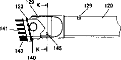
如图33~图37所示,延长吸入管6由粗细不同的多个吸入管120、121、122滑动自如地结合而形成。细吸入管120的前端设有利用转动能够替换的替换吸口123。As shown in FIGS. 33 to 37 , the
延长吸入管6伸缩自如。拉长后扫除天花板等高处。缩短后扫除狭窄处。Prolong
延长吸入管6具备吸入管闭锁机构124、125。The
吸入管闭锁机构125设置在粗吸入管122的前侧。吸入管闭锁机构125具有配合突起126。该配合突起126配合在中粗吸入管121的配合孔上,能够保持伸长状态。The suction
若吸入管闭锁机构125的旋钮127向W方向移动,则配合突起126从配合孔脱离,能够解除吸入管闭锁机构125的约束。能收缩以便使中粗吸入管121收放在粗吸入管122中。When the knob 127 of the suction
吸入管闭锁机构124设置在中粗吸入管121的前侧。吸入管闭锁机构124具有杆128,杆128的内端突起配合到细吸入管120的配合孔129中,能够保持伸长状态。The suction
若将中粗吸入管121收放到粗吸入管122中,则杆128碰到吸入管闭锁机构125,进而杆128向外周方向动作。利用该动作杆128的内端突起从细吸入管120的配合孔129脱离,因此能够解除吸入管闭锁机构124的约束。能收缩以便使细吸入管120收放在中粗吸入管121中。When the medium
如此地,利用吸入管闭锁机构的约束能够切实地保持延长吸入管6的伸长状态。通过解除吸入管闭锁机构的约束,能够容易地缩短延长吸入管6。In this way, the extended state of the
利用支撑轴140替换吸口123转动自如地被支撑在细吸入管120的前端。替换吸口123具有两个吸口部141、142。吸口部141设有刷子143。The tip of the
通过转动替换吸口123,能够替换无刷子的吸口部142(图42)和有刷子的吸口部142(图43)。By rotating the
设定无刷子的吸口部142时,如图39所示利用锁销的保持机构144(凹凸),能够保持该状态。When setting the
设定有刷子的吸口部142时,如图40、图41所示利用锁销的保持机构145(突起),能够保持该状态。When the
如此地,利用转动进行替换吸口的替换因此很方便。另外,利用锁销的保持机构能够保持双方的替换状态,因此不是在使用中简单地转动收放替换吸口,便于使用。In this way, it is convenient to replace the replacement nozzle by turning it. In addition, the holding mechanism using the lock pin can maintain the replacement state of both sides, so the replacement suction mouth does not need to be simply turned and retracted during use, which is convenient for use.
如图31、图32所示,收放延长吸入管6的收放筒部9r底部封闭。收放筒部9在接收口处具有环状的密封件146。延长吸入管6的粗吸入管122的外周设有凸缘147。As shown in Fig. 31 and Fig. 32, the bottom of the retractable cylindrical part 9r of the retractable and
若将缩短的延长吸入管6插入到收放筒部9中,则凸缘147贴紧到密封件146上能够保证气密。收放筒部9的底部封闭,因此能够阻断延长吸入管6的吸入。只有吸入体2的吸入,因此能够顺利进行吸入体2的吸入。If the shortened
如此地,阻断延长吸入管6的吸入但不设置断流阀,因此构成简单且廉价。另外,延长吸入管6收放筒部9内能够阻止延长吸入管6的吸入,因此操作简单。In this way, the suction of the
收放筒部9具有吸入管保持机构148。吸入管保持机构148设置在收放筒部9的接收口处。吸入管保持机构148具有销锁149、销锁加力弹簧150以及返回杆151。The
通过将延长吸入管6插入到收放筒部9,销锁149配合凸缘147,切实地被保持在收放筒部9中。因此,没有在利用吸入体2的地面扫除中延长吸入管6从收放筒部9取下对扫除带来障碍的情况。When the
使销锁149后退而转动返回杆151,能够容易地从收放筒部9取下延长吸入管6。The
Claims (11)
Applications Claiming Priority (2)
| Application Number | Priority Date | Filing Date | Title |
|---|---|---|---|
| JP2005010678 | 2005-01-18 | ||
| JP2005010678A JP4340629B2 (en) | 2005-01-18 | 2005-01-18 | Upright vacuum cleaner |
Publications (2)
| Publication Number | Publication Date |
|---|---|
| CN1806741A true CN1806741A (en) | 2006-07-26 |
| CN100340201C CN100340201C (en) | 2007-10-03 |
Family
ID=36838959
Family Applications (1)
| Application Number | Title | Priority Date | Filing Date |
|---|---|---|---|
| CNB2005101329394A Expired - Fee Related CN100340201C (en) | 2005-01-18 | 2005-12-29 | Vertical electric dust collector |
Country Status (2)
| Country | Link |
|---|---|
| JP (1) | JP4340629B2 (en) |
| CN (1) | CN100340201C (en) |
Cited By (43)
| Publication number | Priority date | Publication date | Assignee | Title |
|---|---|---|---|---|
| CN102018479A (en) * | 2010-10-19 | 2011-04-20 | 宁波富佳实业有限公司 | Multifunctional vertical dust collector |
| CN102232813A (en) * | 2010-04-21 | 2011-11-09 | 松下电器产业株式会社 | Vertical electric dust collector |
| US20110314629A1 (en) * | 2009-03-13 | 2011-12-29 | G. B. D. Corp. | Surface cleaning apparatus with different cleaning configurations |
| CN102499608A (en) * | 2011-11-18 | 2012-06-20 | 宁波锦隆电器有限公司 | Vertical type dust collector |
| US20140082881A1 (en) * | 2006-12-12 | 2014-03-27 | G.B.D. Corp. | Upright Vacuum Cleaner |
| CN103876687A (en) * | 2012-12-22 | 2014-06-25 | 昆山瑞恒峰技术咨询有限公司 | Dust collector convenient to move and dispose |
| US9015899B2 (en) | 2009-03-13 | 2015-04-28 | G.B.D. Corp. | Surface cleaning apparatus with different cleaning configurations |
| US9198551B2 (en) | 2013-02-28 | 2015-12-01 | Omachron Intellectual Property Inc. | Surface cleaning apparatus |
| US9226633B2 (en) | 2009-03-13 | 2016-01-05 | Omachron Intellectual Property Inc. | Surface cleaning apparatus |
| US9232877B2 (en) | 2010-03-12 | 2016-01-12 | Omachron Intellectual Property Inc. | Surface cleaning apparatus with enhanced operability |
| US9314138B2 (en) | 2013-02-28 | 2016-04-19 | Omachron Intellectual Property Inc. | Surface cleaning apparatus |
| CN105615766A (en) * | 2014-11-03 | 2016-06-01 | 康塔有限公司 | Ground cleaning equipment |
| US9364127B2 (en) | 2013-02-28 | 2016-06-14 | Omachron Intellectual Property Inc. | Surface cleaning apparatus |
| US9386895B2 (en) | 2009-03-13 | 2016-07-12 | Omachron Intellectual Property Inc. | Surface cleaning apparatus |
| US9392916B2 (en) | 2009-03-13 | 2016-07-19 | Omachron Intellectual Property Inc. | Surface cleaning apparatus |
| US9427122B2 (en) | 2009-03-13 | 2016-08-30 | Omachron Intellectual Property Inc. | Surface cleaning apparatus |
| US9456721B2 (en) | 2013-02-28 | 2016-10-04 | Omachron Intellectual Property Inc. | Surface cleaning apparatus |
| US9480373B2 (en) | 2009-03-13 | 2016-11-01 | Omachron Intellectual Property Inc. | Surface cleaning apparatus |
| US9591953B2 (en) | 2009-03-13 | 2017-03-14 | Omachron Intellectual Property Inc. | Surface cleaning apparatus |
| US9693666B2 (en) | 2011-03-04 | 2017-07-04 | Omachron Intellectual Property Inc. | Compact surface cleaning apparatus |
| US9962050B2 (en) | 2016-08-29 | 2018-05-08 | Omachron Intellectual Property Inc. | Surface cleaning apparatus |
| US10136779B2 (en) | 2016-08-29 | 2018-11-27 | Omachron Intellectual Property Inc. | Surface cleaning apparatus |
| US10136780B2 (en) | 2016-08-29 | 2018-11-27 | Omachron Intellectual Property Inc. | Surface cleaning apparatus |
| US10292550B2 (en) | 2016-08-29 | 2019-05-21 | Omachron Intellectual Property Inc. | Surface cleaning apparatus |
| US10299649B2 (en) | 2013-02-28 | 2019-05-28 | Omachron Intellectual Property Inc. | Surface cleaning apparatus |
| US10321794B2 (en) | 2016-08-29 | 2019-06-18 | Omachron Intellectual Property Inc. | Surface cleaning apparatus |
| US10405711B2 (en) | 2016-08-29 | 2019-09-10 | Omachron Intellectual Property Inc. | Surface cleaning apparatus |
| US10413141B2 (en) | 2016-08-29 | 2019-09-17 | Omachron Intellectual Property Inc. | Surface cleaning apparatus |
| US10433686B2 (en) | 2007-08-29 | 2019-10-08 | Omachron Intellectual Property Inc. | Configuration of a surface cleaning apparatus |
| US10433689B2 (en) | 2016-08-29 | 2019-10-08 | Omachron Intellectual Property Inc. | Surface cleaning apparatus |
| US10441125B2 (en) | 2016-08-29 | 2019-10-15 | Omachron Intellectual Property Inc. | Surface cleaning apparatus |
| US10441124B2 (en) | 2016-08-29 | 2019-10-15 | Omachron Intellectual Property Inc. | Surface cleaning apparatus |
| US10548442B2 (en) | 2009-03-13 | 2020-02-04 | Omachron Intellectual Property Inc. | Portable surface cleaning apparatus |
| US10729295B2 (en) | 2016-08-29 | 2020-08-04 | Omachron Intellectual Property Inc. | Surface cleaning apparatus |
| US10765277B2 (en) | 2006-12-12 | 2020-09-08 | Omachron Intellectual Property Inc. | Configuration of a surface cleaning apparatus |
| US11478117B2 (en) | 2016-08-29 | 2022-10-25 | Omachron Intellectual Property Inc. | Surface cleaning apparatus |
| US11612288B2 (en) | 2009-03-13 | 2023-03-28 | Omachron Intellectual Property Inc. | Surface cleaning apparatus |
| US11690489B2 (en) | 2009-03-13 | 2023-07-04 | Omachron Intellectual Property Inc. | Surface cleaning apparatus with an external dirt chamber |
| US11751733B2 (en) | 2007-08-29 | 2023-09-12 | Omachron Intellectual Property Inc. | Portable surface cleaning apparatus |
| US12048409B2 (en) | 2007-03-11 | 2024-07-30 | Omachron Intellectual Property Inc. | Portable surface cleaning apparatus |
| US12220099B2 (en) | 2006-12-12 | 2025-02-11 | Omachron Intellectual Property Inc. | Surface cleaning apparatus |
| US12251716B2 (en) | 2016-12-27 | 2025-03-18 | Omachron Intellectual Property Inc. | Surface cleaning apparatus |
| US12446739B2 (en) | 2009-03-11 | 2025-10-21 | Omachron Intellectual Property Inc. | Hand vacuum cleaner |
Families Citing this family (5)
| Publication number | Priority date | Publication date | Assignee | Title |
|---|---|---|---|---|
| GB2454922A (en) * | 2007-11-23 | 2009-05-27 | Dyson Technology Ltd | Removable head connection member for vacuum cleaner |
| GB2454921A (en) | 2007-11-23 | 2009-05-27 | Dyson Technology Limited | Rotatable electrical connection for cleaner head |
| JP5095639B2 (en) * | 2009-01-13 | 2012-12-12 | シャープ株式会社 | Hinge mechanism |
| JP5840424B2 (en) * | 2011-08-29 | 2016-01-06 | 株式会社東芝 | Electric vacuum cleaner |
| JP2015156884A (en) * | 2014-02-21 | 2015-09-03 | 日立アプライアンス株式会社 | Electric vacuum cleaner |
Family Cites Families (6)
| Publication number | Priority date | Publication date | Assignee | Title |
|---|---|---|---|---|
| US4959885A (en) * | 1990-01-12 | 1990-10-02 | Royal Applicance Mfg. Co. | Vacuum cleaner |
| US6108861A (en) * | 1995-12-06 | 2000-08-29 | Royal Appliance Mfg. Co. | Extendable hose for a vacuum cleaner |
| JP3144309B2 (en) * | 1996-08-02 | 2001-03-12 | 松下電器産業株式会社 | Electric vacuum cleaner |
| EP1052924B1 (en) * | 1998-01-09 | 2010-03-24 | Royal Appliance Manufacturing Co. | Upright vacuum cleaner with cyclonic airflow |
| JP2001078928A (en) * | 1999-09-13 | 2001-03-27 | Hitachi Ltd | Upright type vacuum cleaner |
| KR20010035934A (en) * | 1999-10-05 | 2001-05-07 | 배길성 | Upright type vacuum cleaner |
-
2005
- 2005-01-18 JP JP2005010678A patent/JP4340629B2/en not_active Expired - Fee Related
- 2005-12-29 CN CNB2005101329394A patent/CN100340201C/en not_active Expired - Fee Related
Cited By (80)
| Publication number | Priority date | Publication date | Assignee | Title |
|---|---|---|---|---|
| US11076729B2 (en) | 2006-12-12 | 2021-08-03 | Omachron Intellectual Property Inc. | Upright vacuum cleaner |
| US10765277B2 (en) | 2006-12-12 | 2020-09-08 | Omachron Intellectual Property Inc. | Configuration of a surface cleaning apparatus |
| US9301662B2 (en) * | 2006-12-12 | 2016-04-05 | Omachron Intellectual Property Inc. | Upright vacuum cleaner |
| US12256882B2 (en) | 2006-12-12 | 2025-03-25 | Omachron Intellectual Property Inc. | Upright vacuum cleaner |
| US12220099B2 (en) | 2006-12-12 | 2025-02-11 | Omachron Intellectual Property Inc. | Surface cleaning apparatus |
| US20140082881A1 (en) * | 2006-12-12 | 2014-03-27 | G.B.D. Corp. | Upright Vacuum Cleaner |
| US10076217B2 (en) | 2006-12-12 | 2018-09-18 | Omachron Intellectual Property Inc. | Upright vacuum cleaner |
| US11700984B2 (en) | 2006-12-12 | 2023-07-18 | Omachron Intellectual Property Inc. | Configuration of a surface cleaning apparatus |
| US12048409B2 (en) | 2007-03-11 | 2024-07-30 | Omachron Intellectual Property Inc. | Portable surface cleaning apparatus |
| US11751733B2 (en) | 2007-08-29 | 2023-09-12 | Omachron Intellectual Property Inc. | Portable surface cleaning apparatus |
| US10561286B2 (en) | 2007-08-29 | 2020-02-18 | Omachron Intellectual Property Inc. | Configuration of a surface cleaning apparatus |
| US12324557B2 (en) | 2007-08-29 | 2025-06-10 | Omachron Intellectual Property Inc. | Portable surface cleaning apparatus |
| US10542856B2 (en) | 2007-08-29 | 2020-01-28 | Omachron Intellectual Property Inc. | Configuration of a surface cleaning apparatus |
| US10433686B2 (en) | 2007-08-29 | 2019-10-08 | Omachron Intellectual Property Inc. | Configuration of a surface cleaning apparatus |
| US12446739B2 (en) | 2009-03-11 | 2025-10-21 | Omachron Intellectual Property Inc. | Hand vacuum cleaner |
| US11622659B2 (en) | 2009-03-13 | 2023-04-11 | Omachron Intellectual Property Inc. | Portable surface cleaning apparatus |
| US10327608B2 (en) | 2009-03-13 | 2019-06-25 | Omachron Intellectual Property Inc. | Surface cleaning apparatus with different cleaning configurations |
| US9386895B2 (en) | 2009-03-13 | 2016-07-12 | Omachron Intellectual Property Inc. | Surface cleaning apparatus |
| US9392916B2 (en) | 2009-03-13 | 2016-07-19 | Omachron Intellectual Property Inc. | Surface cleaning apparatus |
| US9427122B2 (en) | 2009-03-13 | 2016-08-30 | Omachron Intellectual Property Inc. | Surface cleaning apparatus |
| US9451852B2 (en) * | 2009-03-13 | 2016-09-27 | Omachron Intellectual Property Inc. | Surface cleaning apparatus with different cleaning configurations |
| US11529031B2 (en) | 2009-03-13 | 2022-12-20 | Omachron Intellectual Property Inc. | Portable surface cleaning apparatus |
| US9480373B2 (en) | 2009-03-13 | 2016-11-01 | Omachron Intellectual Property Inc. | Surface cleaning apparatus |
| US9591953B2 (en) | 2009-03-13 | 2017-03-14 | Omachron Intellectual Property Inc. | Surface cleaning apparatus |
| US11612288B2 (en) | 2009-03-13 | 2023-03-28 | Omachron Intellectual Property Inc. | Surface cleaning apparatus |
| US11330944B2 (en) | 2009-03-13 | 2022-05-17 | Omachron Intellectual Property Inc. | Portable surface cleaning apparatus |
| US9801511B2 (en) | 2009-03-13 | 2017-10-31 | Omachron Intellectual Property Inc. | Surface cleaning apparatus with different cleaning configurations |
| US9907444B2 (en) | 2009-03-13 | 2018-03-06 | Omachron Intellectual Property Inc. | Surface cleaning apparatus with different cleaning configurations |
| US20110314629A1 (en) * | 2009-03-13 | 2011-12-29 | G. B. D. Corp. | Surface cleaning apparatus with different cleaning configurations |
| US9226633B2 (en) | 2009-03-13 | 2016-01-05 | Omachron Intellectual Property Inc. | Surface cleaning apparatus |
| US12251074B2 (en) | 2009-03-13 | 2025-03-18 | Omachron Intellectual Property Inc. | Surface cleaning apparatus with an external dirt chamber |
| US11690489B2 (en) | 2009-03-13 | 2023-07-04 | Omachron Intellectual Property Inc. | Surface cleaning apparatus with an external dirt chamber |
| US9066642B2 (en) | 2009-03-13 | 2015-06-30 | G.B.D. Corp. | Surface cleaning apparatus with different cleaning configurations |
| US11950751B2 (en) | 2009-03-13 | 2024-04-09 | Omachron Intellectual Property Inc. | Surface cleaning apparatus with an external dirt chamber |
| US11896183B2 (en) | 2009-03-13 | 2024-02-13 | Omachron Intellectual Property Inc. | Surface cleaning apparatus with different cleaning configuration |
| US10548442B2 (en) | 2009-03-13 | 2020-02-04 | Omachron Intellectual Property Inc. | Portable surface cleaning apparatus |
| US11571096B2 (en) | 2009-03-13 | 2023-02-07 | Omachron Intellectual Property Inc. | Surface cleaning apparatus with different cleaning configurations |
| US11771278B2 (en) | 2009-03-13 | 2023-10-03 | Omachron Intellectual Property Inc. | Surface cleaning apparatus |
| US11771276B2 (en) | 2009-03-13 | 2023-10-03 | Omachron Intellectual Property Inc. | Surface cleaning apparatus |
| US11771277B2 (en) | 2009-03-13 | 2023-10-03 | Omachron Intellectual Property Inc. | Surface cleaning apparatus |
| US9301663B2 (en) | 2009-03-13 | 2016-04-05 | Omachron Intellectual Property Inc. | Surface cleaning apparatus with different cleaning configurations |
| US9015899B2 (en) | 2009-03-13 | 2015-04-28 | G.B.D. Corp. | Surface cleaning apparatus with different cleaning configurations |
| US11744417B2 (en) | 2009-03-13 | 2023-09-05 | Omachron Intellectual Property Inc. | Surface cleaning apparatus with different cleaning configuration |
| US10512374B2 (en) | 2009-03-13 | 2019-12-24 | Omachron Intellectual Property Inc. | Surface cleaning apparatus with different cleaning configurations |
| US11771275B2 (en) | 2010-03-12 | 2023-10-03 | Omachron Intellectual Property Inc. | Surface cleaning apparatus with enhanced operability |
| US11839342B2 (en) | 2010-03-12 | 2023-12-12 | Omachron Intellectual Property Inc. | Surface cleaning apparatus with enhanced operability |
| US9232877B2 (en) | 2010-03-12 | 2016-01-12 | Omachron Intellectual Property Inc. | Surface cleaning apparatus with enhanced operability |
| US9668631B2 (en) | 2010-03-12 | 2017-06-06 | Omachron Intellectual Property Inc. | Surface cleaning apparatus with enhanced operability |
| CN102232813A (en) * | 2010-04-21 | 2011-11-09 | 松下电器产业株式会社 | Vertical electric dust collector |
| CN102018479B (en) * | 2010-10-19 | 2013-01-23 | 宁波富佳实业有限公司 | Multifunctional vertical dust collector |
| CN102018479A (en) * | 2010-10-19 | 2011-04-20 | 宁波富佳实业有限公司 | Multifunctional vertical dust collector |
| US10602894B2 (en) | 2011-03-04 | 2020-03-31 | Omachron Intellectual Property Inc. | Portable surface cleaning apparatus |
| US11612283B2 (en) | 2011-03-04 | 2023-03-28 | Omachron Intellectual Property Inc. | Surface cleaning apparatus |
| US9693666B2 (en) | 2011-03-04 | 2017-07-04 | Omachron Intellectual Property Inc. | Compact surface cleaning apparatus |
| CN102499608A (en) * | 2011-11-18 | 2012-06-20 | 宁波锦隆电器有限公司 | Vertical type dust collector |
| CN103876687A (en) * | 2012-12-22 | 2014-06-25 | 昆山瑞恒峰技术咨询有限公司 | Dust collector convenient to move and dispose |
| US10624511B2 (en) | 2013-02-28 | 2020-04-21 | Omachron Intellectual Property Inc. | Surface cleaning apparatus |
| US11889968B2 (en) | 2013-02-28 | 2024-02-06 | Omachron Intellectual Property Inc. | Surface cleaning apparatus |
| US9198551B2 (en) | 2013-02-28 | 2015-12-01 | Omachron Intellectual Property Inc. | Surface cleaning apparatus |
| US9456721B2 (en) | 2013-02-28 | 2016-10-04 | Omachron Intellectual Property Inc. | Surface cleaning apparatus |
| US10638897B2 (en) | 2013-02-28 | 2020-05-05 | Omachron Intellectual Property Inc. | Surface cleaning apparatus |
| US9364127B2 (en) | 2013-02-28 | 2016-06-14 | Omachron Intellectual Property Inc. | Surface cleaning apparatus |
| US9931005B2 (en) | 2013-02-28 | 2018-04-03 | Omachron lntellectual Property Inc. | Surface cleaning apparatus |
| US10299649B2 (en) | 2013-02-28 | 2019-05-28 | Omachron Intellectual Property Inc. | Surface cleaning apparatus |
| US9314138B2 (en) | 2013-02-28 | 2016-04-19 | Omachron Intellectual Property Inc. | Surface cleaning apparatus |
| CN105615766A (en) * | 2014-11-03 | 2016-06-01 | 康塔有限公司 | Ground cleaning equipment |
| US10405711B2 (en) | 2016-08-29 | 2019-09-10 | Omachron Intellectual Property Inc. | Surface cleaning apparatus |
| US12161281B2 (en) | 2016-08-29 | 2024-12-10 | Omachron Intellectual Property Inc. | Surface cleaning apparatus |
| US10321794B2 (en) | 2016-08-29 | 2019-06-18 | Omachron Intellectual Property Inc. | Surface cleaning apparatus |
| US10413141B2 (en) | 2016-08-29 | 2019-09-17 | Omachron Intellectual Property Inc. | Surface cleaning apparatus |
| US10433689B2 (en) | 2016-08-29 | 2019-10-08 | Omachron Intellectual Property Inc. | Surface cleaning apparatus |
| US10292550B2 (en) | 2016-08-29 | 2019-05-21 | Omachron Intellectual Property Inc. | Surface cleaning apparatus |
| US10136780B2 (en) | 2016-08-29 | 2018-11-27 | Omachron Intellectual Property Inc. | Surface cleaning apparatus |
| US11478117B2 (en) | 2016-08-29 | 2022-10-25 | Omachron Intellectual Property Inc. | Surface cleaning apparatus |
| US10136779B2 (en) | 2016-08-29 | 2018-11-27 | Omachron Intellectual Property Inc. | Surface cleaning apparatus |
| US10441125B2 (en) | 2016-08-29 | 2019-10-15 | Omachron Intellectual Property Inc. | Surface cleaning apparatus |
| US10729295B2 (en) | 2016-08-29 | 2020-08-04 | Omachron Intellectual Property Inc. | Surface cleaning apparatus |
| US9962050B2 (en) | 2016-08-29 | 2018-05-08 | Omachron Intellectual Property Inc. | Surface cleaning apparatus |
| US10441124B2 (en) | 2016-08-29 | 2019-10-15 | Omachron Intellectual Property Inc. | Surface cleaning apparatus |
| US12251716B2 (en) | 2016-12-27 | 2025-03-18 | Omachron Intellectual Property Inc. | Surface cleaning apparatus |
Also Published As
| Publication number | Publication date |
|---|---|
| JP2006198010A (en) | 2006-08-03 |
| JP4340629B2 (en) | 2009-10-07 |
| CN100340201C (en) | 2007-10-03 |
Similar Documents
| Publication | Publication Date | Title |
|---|---|---|
| CN100340201C (en) | Vertical electric dust collector | |
| CN108135414B (en) | Low profile surface cleaning head | |
| CN1169488C (en) | Extension pipes in vacuum cleaners | |
| CN1284500C (en) | Multi-stage cyclonic vacuum cleaner | |
| CN1589722A (en) | Electric vacuum cleaner, and vacuum cleaner hose | |
| CN100340202C (en) | Rotary cleaning body, suction port portion of electric vacuum cleaner, and method of manufacturing rotary cleaning body | |
| CN1208597A (en) | electric vacuum cleaner | |
| CN1144567C (en) | Ground suction nozzle of electric sweeping appts. | |
| KR100500841B1 (en) | Inhalation unit of vacuum cleaner | |
| CN1626024A (en) | Upright type vacuum cleaner | |
| CN1788671A (en) | Stacked tank setup for cleaning equipment | |
| WO2014205923A1 (en) | Suction and blowing apparatus | |
| CN1605315A (en) | Vacuum cleaner | |
| KR20140136553A (en) | Vacuum Cleaner | |
| KR100429479B1 (en) | Electric cleaner | |
| CN1644150A (en) | Hand-held vacuum cleaner with filter indicator | |
| CN1642466A (en) | Suction cleaner | |
| US20060042041A1 (en) | Vacuum cleaner and suction nozzle structure thereof | |
| CN2724606Y (en) | Electric vacuum cleaner | |
| CN1281676A (en) | Vacuum cleaner | |
| CN1168415C (en) | electric vacuum cleaner | |
| CN2613226Y (en) | Dust suction device for hand-held power tool | |
| CN200970200Y (en) | Suction nozzle and vacuum cleaner using the same | |
| TW201336463A (en) | Blowing/sucking dual-purpose vacuum cleaner and its fan | |
| CN1139358C (en) | electric vacuum cleaner |
Legal Events
| Date | Code | Title | Description |
|---|---|---|---|
| C06 | Publication | ||
| PB01 | Publication | ||
| C10 | Entry into substantive examination | ||
| SE01 | Entry into force of request for substantive examination | ||
| C14 | Grant of patent or utility model | ||
| GR01 | Patent grant | ||
| CF01 | Termination of patent right due to non-payment of annual fee |
Granted publication date: 20071003 Termination date: 20151229 |
|
| EXPY | Termination of patent right or utility model |