CN1670879A - Electromagnetic relay - Google Patents
Electromagnetic relay Download PDFInfo
- Publication number
- CN1670879A CN1670879A CNA2005100517517A CN200510051751A CN1670879A CN 1670879 A CN1670879 A CN 1670879A CN A2005100517517 A CNA2005100517517 A CN A2005100517517A CN 200510051751 A CN200510051751 A CN 200510051751A CN 1670879 A CN1670879 A CN 1670879A
- Authority
- CN
- China
- Prior art keywords
- contact
- spring
- guide rod
- load
- electromagnetic relay
- Prior art date
- Legal status (The legal status is an assumption and is not a legal conclusion. Google has not performed a legal analysis and makes no representation as to the accuracy of the status listed.)
- Granted
Links
Images


Classifications
-
- H—ELECTRICITY
- H01—ELECTRIC ELEMENTS
- H01H—ELECTRIC SWITCHES; RELAYS; SELECTORS; EMERGENCY PROTECTIVE DEVICES
- H01H50/00—Details of electromagnetic relays
- H01H50/54—Contact arrangements
- H01H50/546—Contact arrangements for contactors having bridging contacts
Landscapes
- Physics & Mathematics (AREA)
- Electromagnetism (AREA)
- Switch Cases, Indication, And Locking (AREA)
- Electromagnets (AREA)
Abstract
一种电磁继电器,不提高触点弹簧的载荷而可以确保必要的触点压力。通过导杆(21)对抗复位弹簧(23)而向固定触点(48)侧移动,使接触片(34)的可动触点(35)完全吸着到固定触点(48)上,导杆(21)上设置平面突起部(33),并装设有在两侧形成截面“コ”形的板簧片部(37)的弹簧用辅助部件(36),该弹簧用辅助部件(36)固定在接触片(34)上,通过导杆的移动而使板簧片部被推碰到平面突起部,从而使该板簧片部弯曲、在可动触点即将完全吸着到固定触点之前产生板簧片部的负荷(F3),将触点弹簧(39)的触点弹簧载荷(F2)和负荷(F3)作为使可动触点完全吸着到固定触点上的触点压力而作用于接触片上。
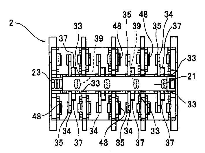
An electromagnetic relay that ensures the necessary contact pressure without increasing the load of the contact spring. The guide rod (21) moves toward the fixed contact (48) side against the return spring (23), so that the movable contact (35) of the contact piece (34) is completely attracted to the fixed contact (48), and the guide rod (21) is provided with planar protruding part (33), and is equipped with the spring auxiliary part (36) that forms the plate spring part (37) of section " U " shape on both sides, and this spring auxiliary part (36) Fixed on the contact piece (34), the leaf spring part is pushed against the flat protrusion by the movement of the guide rod, so that the leaf spring part is bent, and the movable contact is about to be completely attracted to the fixed contact The load (F3) of the plate spring part is generated, and the contact spring load (F2) and load (F3) of the contact spring (39) act as contact pressure to completely attract the movable contact to the fixed contact on the contact sheet.
Description
技术领域technical field
本发明涉及可以作为高电容功率继电器等使用的、特别是改良了触点接触机构的电磁继电器。The invention relates to an electromagnetic relay which can be used as a high-capacitance power relay and the like, especially an improved contact mechanism.
背景技术Background technique
如图23至图26所示,现有的电磁继电器由电磁动作部101和触点块102构成,电磁动作部101的结构为:在外壳104内容纳电磁构件105和铁片106,通过将电磁构件105的线圈105A励磁,而使该铁芯的磁极部107产生引力,以其支点部106A为中心向左摇动铁片106。As shown in Fig. 23 to Fig. 26, the existing electromagnetic relay is composed of an
而且,触点块102具有基座108、导杆109、端子台110、复位弹簧111,如图25(1)所示,端子台110上设置导杆容纳部118和触点配置部120,触点配置部120上配置固定触点121。如图24所示,导杆109具有可以分解为上下的一个以及另一个导杆本体109A、109B,在一个导杆本体109A的图24中,在左端部向上方突出设置一个导杆突起部112,而且,另一个导杆本体109B的图24中,在右端部向下方突出设置另一个导杆突起部113。而且,在一个导杆突起部112的基部形成复位弹簧容纳部112A,在另一个突起部113上形成卡合凹部(未图示)。Moreover, the
而且,在一个导杆本体109A上在导杆109的纵向形成四个接触片插入部114,如图25(1)所示,接触片插入部114的端部设置弹簧容纳部114A。Moreover, four contact
而且,接触片115上,在其左面部(固定触点相对面部)的两端部固定可动触点116。Further,
而且,接触片插入部114的弹簧容纳部114A中容纳触点弹簧117,触点弹簧117抵接到接触片115的中央部,在接触片插入部114的图25(2)中,接触片115由触点弹簧117的弹力推动而被推碰到左侧的端壁部。在该情况下,接触片115的两端部位于触点配置部120内,可动触点116与固定触点121对置。Moreover, the
而且,导杆109容纳在端子台110的导杆容纳部118内,一个导杆突起部112插入在导杆容纳部118的天棚部设置的开口部(都未图示),而且另一个导杆突起部113插入基座108的插入用开口部108A。而且,导杆109由于复位弹簧111的弹力而位于图25(1)所示的复位状态。Furthermore, the
而且,通过将触点块102连接到电磁开关动作部101而构成电磁继电器。在该情况下,设置在铁片106的上边部的卡合突起部106B可摇动地与另一个导杆突起部113的卡合凹部卡合。Furthermore, an electromagnetic relay is constituted by connecting the
在没有将电磁构件105的线圈105A励磁的状态下,导杆109由于复位弹簧111的复位弹簧载荷(弹力)而位于复位状态。In a state where the
通过使电磁构件105的线圈105A励磁,而使铁芯的磁极部107产生引力,以其支点部106A为中心在图23中向左摇动铁片106,使导杆109抵抗复位弹簧111而移动并使可动触点116接触固定触点121。By exciting the
而且,作为现有的电磁继电器,有由电磁铁部和端子台和绝缘板和外壳构成的电磁继电器。即,由端子台和绝缘板形成基座,在其中央设置的滑动槽中自由滑动地组装导杆,在滑动槽的两侧对置的以等间隔配置的多个室部内分别设置触点端子的固定端子,接触片由触点弹簧推动,从导杆的两侧使以等间隔在侧方突出的接触片的可动触点可接触或离开地与固定端子对置,对电磁铁部通电而将线圈励磁,使可动铁片转动并使导杆抗拒复位弹簧而移动而将可动触点压在固定触点上(参照专利文献1)。Furthermore, as conventional electromagnetic relays, there is an electromagnetic relay composed of an electromagnet portion, a terminal block, an insulating plate, and a case. That is, the base is formed by the terminal block and the insulating plate, the guide bar is slidably assembled in the sliding groove provided in the center, and the contact terminals are respectively arranged in a plurality of chambers arranged at equal intervals on both sides of the sliding groove. The fixed terminal of the fixed terminal, the contact piece is pushed by the contact spring, and the movable contact of the contact piece protruding from the side at equal intervals can be contacted or separated from the fixed terminal from both sides of the guide rod, and the electromagnet part is energized And the coil is excited, the movable iron piece is rotated and the guide rod is moved against the return spring to press the movable contact on the fixed contact (refer to Patent Document 1).
【专利文献1】(日本)特开平5-342964号公报[Patent Document 1] (Japanese) Unexamined Patent Publication No. 5-342964
在上述现有的两电磁继电器中,其触点接触机构从导杆109和接触片115和触点弹簧117的结构得到触点压力。在这样的触点接触机构中,如图25(2)所示,为了抑制触点接触时的可动触点116的离开(跳动、振动)以及电流通电造成的温度上升,而有必要增大触点弹簧117的载荷而得到触点压力。In the above-mentioned existing two electromagnetic relays, the contact mechanism obtains the contact pressure from the structure of the
因此,如图26所示,根据继电器的负荷载荷和线圈引力的关系,有必要从线圈引力A提升到线圈引力B,而且伴随于此,而有必要将触点弹簧载荷A提升到触点弹簧载荷B,产生消耗电力增大的问题。而且,为了抑制线圈105A的消耗电力,而产生制约触点弹簧117的载荷,接触片115的振动造成的离开、发热等问题。Therefore, as shown in Fig. 26, according to the relationship between the load of the relay and the coil attractive force, it is necessary to increase from the coil attractive force A to the coil attractive force B, and with this, it is necessary to increase the contact spring load A to the contact spring load A. The load B has a problem of increased power consumption. In addition, in order to suppress the power consumption of the
发明内容Contents of the invention
本发明为了改善上述现有的问题而完成,其目的在于提供一种可以确保必要的触点压力而不增加触点弹簧的载荷(不增加线圈的消耗电力)的电磁继电器。The present invention was made to improve the above-mentioned conventional problems, and an object of the present invention is to provide an electromagnetic relay capable of securing a necessary contact pressure without increasing the load of the contact spring (without increasing the power consumption of the coil).
为了达成上述目的,本发明的电磁继电器中,由导杆载置包括可动触点的接触片和将该接触片推动到固定触点侧的触点弹簧,由线圈的励磁产生的引力进行该导杆的移动,同时由复位弹簧的弹力进行导杆的复位,其中,包括在可动触点即将完全吸着于固定触点上之时,产生通过抗拒导杆的复位弹簧而向固定触点侧的移动作用于接触片的负荷的负荷产生部件,将触点弹簧的触点弹簧载荷和所述负荷,作为使可动触点完全吸着于固定触点的触点压力而作用于接触片。In order to achieve the above object, in the electromagnetic relay of the present invention, the contact piece including the movable contact and the contact spring that pushes the contact piece to the fixed contact side are placed on the guide rod, and the attractive force generated by the excitation of the coil performs the contact spring. The movement of the guide rod, and the reset of the guide rod by the elastic force of the return spring, including when the movable contact is about to be completely absorbed on the fixed contact, the return spring that resists the guide rod will move to the fixed contact side. The load generating member that moves the load acting on the contact piece acts the contact spring load of the contact spring and the load as a contact pressure that completely attracts the movable contact to the fixed contact and acts on the contact piece.
根据该结构,在完全吸着状态下,作为触点压力得到触点弹簧载荷和负荷产生部件产生的负荷,在该情况下,由于在可动触点即将完全吸着于固定触点之时产生所述负荷,所以,不必将触点弹簧的载荷增大(增加线圈的消耗电力)以得到触点压力,由于对引力特性没有影响,所以可以不增加线圈的引力而确保必要的触点压力。According to this structure, in the fully adsorbed state, the contact spring load and the load generated by the load generating member are obtained as the contact pressure. In this case, since the movable contact is about to be completely adsorbed to the fixed contact Therefore, it is not necessary to increase the load of the contact spring (increase the power consumption of the coil) to obtain the contact pressure. Since it has no effect on the attractive force characteristics, the necessary contact pressure can be ensured without increasing the attractive force of the coil.
而且,在上述本发明的电磁继电器中,负荷产生部件包括具有在两端部形成截面“コ”形状的板簧片部的弹簧用辅助部件,该弹簧用辅助部件固定到接触片上,导杆上设置平面突起部,通过导杆的移动而使所述板簧片部被推碰到平面突起部,而使板簧片部弯曲,在该板簧片部产生负荷。Moreover, in the above-mentioned electromagnetic relay of the present invention, the load generating member includes an auxiliary member for a spring having a plate spring part having a cross-sectional "U" shape formed at both ends, and the auxiliary member for spring is fixed to the contact piece, and the guide rod is fixed to the contact piece. A planar protrusion is provided, and the leaf spring is pushed against the planar protrusion by the movement of the guide rod to bend the leaf spring and generate a load on the leaf spring.
而且,在上述本发明的电磁继电器的另一实施例中,负荷产生部件由板簧片部构成,所述板簧片部被设置在导杆上,并通过导杆的移动而被推碰到接触片上,从而弯曲并产生负荷。Moreover, in another embodiment of the electromagnetic relay of the present invention described above, the load generating member is constituted by a plate spring portion which is provided on the guide rod and pushed against by the movement of the guide rod. on the contact piece, thereby bending and generating a load.
而且,在上述本发明的电磁继电器中,弹簧辅助部件和板簧片部采用金属材料以提高导热性。Furthermore, in the above-mentioned electromagnetic relay of the present invention, metal materials are used for the spring auxiliary member and the plate spring portion to improve thermal conductivity.
根据该结构,如果将这些材料设为金属(例如铜系金属),则可以得到触点温度上升的散热效果。According to this structure, if these materials are made of metals (for example, copper-based metals), it is possible to obtain a heat dissipation effect that increases the temperature of the contacts.
根据该结构,在完全吸着状态下,作为触点压力而得到触点弹簧载荷和负荷产生部件产生的负荷,在该情况下,由于在可动触点即将完全吸着到固定触点上时产生负荷,所以没有必要增加触点弹簧的载荷(提高线圈的消耗电力)以得到触点压力,不提高线圈的引力而可以确保必要的触点压力。According to this structure, in the fully attracted state, the contact spring load and the load generated by the load generating member are obtained as the contact pressure. , so there is no need to increase the load of the contact spring (increase the power consumption of the coil) to obtain the contact pressure, and the necessary contact pressure can be ensured without increasing the attractive force of the coil.
附图说明Description of drawings
图1是本发明的电磁继电器的立体图。Fig. 1 is a perspective view of an electromagnetic relay of the present invention.
图2是同一电磁继电器中的电磁继电器本体的立体图。Fig. 2 is a perspective view of an electromagnetic relay body in the same electromagnetic relay.
图3是同一的电磁继电器本体的装配状态的立体图。Fig. 3 is a perspective view of an assembled state of the same electromagnetic relay body.
图4是本发明的电磁继电器中的电磁构件的装配状态的立体图。4 is a perspective view of an assembled state of electromagnetic components in the electromagnetic relay of the present invention.
图5是同一电磁继电器中的触点块的装配状态的立体图。Fig. 5 is a perspective view of an assembled state of contact blocks in the electromagnetic relay.
图6是同一触点块中的基座的立体图。Figure 6 is a perspective view of a base in the same contact block.
图7是同一触点块中的导杆的立体图。Figure 7 is a perspective view of a guide rod in the same contact block.
图8是同一接触片的立体图。Fig. 8 is a perspective view of the same contact piece.
图9是导杆复位时的说明图。Fig. 9 is an explanatory diagram when the guide rod is reset.
图10是同一触点块的端子台的立体图。Fig. 10 is a perspective view of a terminal block of the same contact block.
图11(1)、(2)、(3)是电磁继电器本体的动作说明图。Fig. 11 (1), (2), (3) are action explanatory diagrams of the electromagnetic relay body.
图12是用于同一电磁继电器本体中的特性说明的线图。Fig. 12 is a graph used for description of characteristics in the same electromagnetic relay body.
图13是辅助触点块的立体图。Fig. 13 is a perspective view of an auxiliary contact block.
图14是辅助触点块的装配状态的立体图。Fig. 14 is a perspective view of an assembled state of the auxiliary contact block.
图15是辅助触点块中的导杆的立体图。Fig. 15 is a perspective view of a guide rod in an auxiliary contact block.
图16是同一导杆的另一个导杆本体的立体图。Fig. 16 is a perspective view of another guide rod body of the same guide rod.
图17是接触片的立体图。Fig. 17 is a perspective view of a contact piece.
图18是导杆中的可动触点和固定触点的配置说明图。Fig. 18 is an explanatory view showing the arrangement of movable contacts and fixed contacts in the guide rod.
图19(1)、(2)、(3)是辅助触点块的动作说明图。19(1), (2), and (3) are diagrams illustrating the operation of the auxiliary contact block.
图20是导杆包括的触点接触机构的变形例的立体图。20 is a perspective view of a modified example of the contact mechanism included in the guide rod.
图21是导杆包括的其它的触点接触机构的变形例的立体图。Fig. 21 is a perspective view of another modified example of the contact mechanism included in the guide rod.
图22是触点接触机构的变形例的说明图。FIG. 22 is an explanatory diagram of a modified example of the contact mechanism.
图23是现有的电磁继电器的纵截面图。Fig. 23 is a longitudinal sectional view of a conventional electromagnetic relay.
图24是同一电磁继电器中的包括触点接触机构的导杆的立体图。Fig. 24 is a perspective view of a guide rod including a contact mechanism in the same electromagnetic relay.
图25(1)、(2)是导杆的从复位时到吸引时的动作说明图。Fig. 25 (1), (2) is an explanatory diagram of the operation of the guide rod from the time of reset to the time of suction.
图26是同一电磁继电器中的特性说明的线图。Fig. 26 is a diagram illustrating characteristics of the same electromagnetic relay.
具体实施方式Detailed ways
参照附图详细叙述本发明的实施方式。Embodiments of the present invention will be described in detail with reference to the drawings.
图1至图22表示本发明的实施方式。图1是本发明的电磁继电器的立体图,图2是同一电磁继电器中的电磁继电器本体的立体图,图3是同一的电磁继电器本体的装配状态的立体图,图4是本发明的电磁继电器中的电磁构件的装配状态的立体图,图5是同一电磁继电器中的触点块的装配状态的立体图。1 to 22 show embodiments of the present invention. Fig. 1 is the perspective view of the electromagnetic relay of the present invention, Fig. 2 is the perspective view of the electromagnetic relay body in the same electromagnetic relay, Fig. 3 is the perspective view of the assembled state of the same electromagnetic relay body, Fig. 4 is the electromagnetic relay in the electromagnetic relay of the
如图1所示,本发明的电磁继电器将电磁动作部1、触点构件2、辅助触点块3一体构成。而且,由电磁动作部1和触点构件2构成电磁继电器本体F。另外,图1中,J是可装卸地安装在电磁继电器本体F中的AC操作单元。As shown in FIG. 1 , the electromagnetic relay of the present invention is composed of an
如图3以及图4所示,电磁动作部1包括外壳4、电磁构件11、铁片12。As shown in FIGS. 3 and 4 , the
在外壳4的横向的侧壁部部4a、4b的中央部,在纵向上形成凹部5。在该凹部5的下部设置安装座部6。而且,在侧壁部4a、4b上,在图4中位于左侧部设置端子用窗部7。A recessed
而且,侧壁部4a、4b以及外壳4的纵向的互相对置的一个端壁部4c上设置卡紧孔部8,在另一个端壁部4d的内面上形成一对间隔壁部9,间隔壁部9之间为铁片容纳部10A,除去该铁片容纳部10A的部分为电磁构件容纳部10B。而且,在铁片容纳部10A的底部设置铁片12的支承部(未图示)。Moreover, a
电磁构件11具有在两端部有凸肩部14A、14B的卷线筒14,该卷线筒14上缠绕有线圈15,而且,卷线筒14的中心孔14a中插过铁芯13,该铁芯13的图4中,右端部为磁极部13A。The
而且,卷线筒14上配置磁轭16,该磁轭16的弯曲端部固定在铁芯13的左端部(未图示)。而且,凸肩部14A上设置线圈端子17。Further, a
而且,如图4所示,铁片12有长方形的铁片本体12A,该铁片本体12A的两侧边部的下部设置支点部18。而且,铁片本体12A的上边部的中央设置卡合突起部19。Furthermore, as shown in FIG. 4 , the
而且,如图3所示,外壳4的电磁构件容纳部10B中容纳电磁构件11,铁片容纳部10A中容纳铁片12。在该情况下,电磁构件11的线圈端子17插入外壳4的端子用窗部7,而且,铁片12的支点部18由铁片容纳部10A的支承部可摇动地支承。而且,该铁片12与电磁构件11的铁芯13的磁极部13A对置。Furthermore, as shown in FIG. 3 , the
如图3以及图5所示,触点块部2有基座20、导杆21、具有端子台22A的构件本体22、以及复位弹簧23。As shown in FIGS. 3 and 5 , the
如图5以及图6所示,基座20具有长方形的底面部20A、基座20的横向的前、后侧壁部20B、20C、基座20的纵向的端壁部20D、20E,如图6所示,底面部20A上,以一对支脚承担部25a、25b为一组,在底面部20A的纵向上在两列上设置多个组。As shown in FIGS. 5 and 6, the
而且,如图6所示,侧壁部20B、20C上隔开预定的间隔形成多个卡合槽部26,而且,端壁部20D、20E上分别设置一对卡紧孔部27。而且,基座20上,在底面部20A的纵向的两端部分别设置卡紧爪部28。Furthermore, as shown in FIG. 6 , a plurality of
导杆21在图7中,具有可以上下分解的一个以及另一个导杆本体21A、21B,在一个导杆本体21A的图7中,在左端部向上突出设置一个导杆突起部29。在一方的导杆突起部29的基部形成复位弹簧容纳部29A。而且,在另一个导杆本体21B的图7中,在右端部向下突出设置另一个导杆突起部30,在该另一个导杆突起部30上形成卡合凹部30A。In FIG. 7 , the
而且,在一个导杆本体21A上,在导杆21的纵向上形成四个从其一个侧面部21a穿过另一个侧面部21b的长方形接触片插入部31,如图9所示,在接触片插入部31的图9中,在右侧的端面部31a上设置弹簧容纳部32。而且,在两侧面部21a、21b上,位于在接触片插入部31的端面部31a侧,设置平面突起部33。Moreover, on one guide rod body 21A, four rectangular contact
而且,如图8所示,在接触片34上,在其表面(固定触点对置面部)34a的两端部固定可动触点35,在接触片34的背面部(与固定触点对置面部34a相反侧的面部)34b上安装弹簧用辅助部件36。And, as shown in FIG. 8, on the
该弹簧用辅助部件36,通过其弹性材料构成的长方形的部件本体36A的前、后部弯曲为“コ”字型而形成板簧片部37,在部件本体36A的两边缘部分别形成一对卡紧片部38而构成,弹簧用辅助部件36在沿着接触片34的背面部34b的状态下,通过将卡紧片部38卡紧在接触片34的两边缘部,而安装在接触片34上。而且,弹簧用辅助部件36的中央部为触点弹簧抵接部36B。The spring auxiliary member 36 is formed by bending the front and rear parts of the rectangular member body 36A made of elastic material into a "U" shape to form a
然后,如图9所示,接触片插入部31内插入接触片34,而且,弹簧容纳部32内容纳触点弹簧39。而且,触点弹簧39抵接到接触片34的触点弹簧抵接部36B上,接触片34通过触点弹簧39的弹力被推动而在接触片插入部31的图9中被推碰到左侧的端面部31b上。而且,由导杆21、由该导杆21载置的接触片34、可动触点35、触点弹簧39、平面突起部33、后述的固定触点48构成触点接触机构。Then, as shown in FIG. 9 , the contact
构件本体22上,如图10所示,在其纵向上形成端壁部22B、22C,在端壁部22B、22C之间形成导杆容纳部40和触点配置部41。而且,组件本体22上,在隔着导杆容纳部40的两侧上设置多个端子安装部42。On the
在导杆容纳部40的天棚部40A,位于端壁部22B侧形成长方形的插入凹部43,该插入凹部43的底部上设置长方形的开口部44。而且,端壁部22B上设置穿过插入凹部43的卡紧孔部22D。A
而且,端子安装部42通过将端壁部22B、22C之间由多个间隔壁部45间隔而分区,端壁部22B、22C以及间隔壁部45在图10中向下方延伸,这些延伸部为支脚部46。Furthermore, the
这些支脚部46之间为上述触点配置部41,触点配置部41位于导杆容纳部40的两侧。而且,端壁部22B、22C的支脚部46上设置卡紧爪部47。Between these
然后,如图5以及图9所示,各触点配置部41上配置固定端子48A的固定触点48,固定端子48A配置于端子安装部42。Then, as shown in FIGS. 5 and 9 , the fixed
然后,外壳20内配置导杆21和构件本体22,位于构件本体22的导杆容纳部40的两侧的支脚部46由支脚承担部25a、25b定位,构件本体22的间隔壁部45卡合在外壳20的侧壁部20B、20C的卡合沟部26中,构件本体22的卡紧爪部47卡紧在外壳20的卡紧孔部27中。Then, the
在该状态下,导杆21可移动地容纳在构件本体22的导杆容纳部40内,一个导杆突起部29插入导杆容纳部40的开口部44中,而另一个导杆突起部30插入外壳20的插入用开口部24中。In this state, the
然后,一个导杆突起部29的复位弹簧容纳部29A中容纳复位弹簧23,导杆21由于该复位弹簧23的弹力而位于图11(1)所示的复位状态。Then, the return spring 23 is accommodated in the return spring accommodating portion 29A of one
即,在该复位状态下,导杆21处于行程0的位置,各接触片34由于各个触点弹簧39的弹力而被押在接触片插入部31的端面部31b上,接触片34上设置的可动触点35离开固定触点48,弹簧用辅助部件36的板簧片部37离开平面突起部33。That is, in this reset state, the
通过将如上述那样组装的触点构件2连接到电磁动作部1上而构成电磁继电器本体F。通过将在外壳20的底面部20A上设置的各个卡紧爪部28可装卸地卡紧在外壳的卡紧孔部8而进行该连接。The electromagnetic relay main body F is formed by connecting the
这样,在触点构件2被连接在电磁动作部1上的状态下,铁片12的上边部上设置的卡紧突起部19可摇动地卡紧在从外壳20的插入用开口部24突出的另一个导杆突起部30的卡合凹部30A。In this way, in the state where the
然后,由弹簧用辅助部件36的板簧片部37和平面突起部33构成负荷产生部件。Then, the load generating member is constituted by the plate
如图13至19所示,辅助触点块3由具有基座61、导杆62、端子台63A的块本体63构成。As shown in FIGS. 13 to 19 , the
基座61具有长方形的底面部61A和基座的横向的侧壁部61B、61C,如图14所示,底面部61A上,位于其中央形成插入用开口部64。而侧壁部61B、61C上形成卡合沟部65和卡紧孔部66,而且,基座61上,在底面部61A的纵向的一端部设置卡紧爪部67。The
导杆62,在图15中具有可以上下分解的导杆体62A、62B,一个导杆体62A通过在与另一个导杆体62B的上面部吻合的基座部74上突出设置导杆部75而构成,在该导杆部75的顶部上设置钮部76。而且,基座部74上设置卡紧销(未图示)。The
另一个导杆体62B上,其上面部的纵向上设置两个接触片安装部68,而且,上面部的中央设置销孔69。接触片安装部68由孔部70和从该孔部70的周面部穿过两侧面部62a、62b的切口部71构成。而且,另一个导杆体62B的下侧的面部上突出设置一对支脚部72,这些支脚部72之间为突起插入部73。On the other
上述接触片安装部68上安装接触片80。即,如图17所示,该接触片80,其长方形的弹簧材料构成的接触片本体80A的中央部形成半圆形作为配合部81,接触片本体80A的配合部81的两侧的弹簧片部82上,从各个端缘部82a在配合部81侧形成切口部83,在两弹簧片部82的前部固定可动触点84。A
然后,这样构成的接触片80,其配合部81与孔部70配合,同时通过将两板簧片部82的基部插入切口部71而安装在接触片安装部68上。Then, the thus constituted
然后,将卡紧销卡紧到另一个导杆体62B的上面部的销孔69中,通过使一个导杆体62A的基座部74和另一个导杆体70B的上面部吻合,将一个导杆体62A安装到另一个导杆体62B上而构成导杆62。Then, the clamping pin is clamped into the
如图14所示,块本体63上设置端壁部63B、63C,和位于这些端壁部63B、63C之间的导杆容纳部85。在该天棚部85A上,位于其中央形成长方形的开口部86。而且,在隔着导杆容纳部85的两侧设置多个端子安装部87。通过这些间隔壁部89而被间隔。As shown in FIG. 14 , the
而且,端壁部63B、63C以及间隔壁部89在图14中向下方延伸处,这些延伸部90之间为触点配置部91,触点配置部91位于导杆容纳部85的两侧。而且,端子安装部87的底部外面上设置卡紧爪部92。Furthermore, the
而且,各触点配置部91上配置固定端子93A的固定触点93,固定端子93A配置于端子安装部87上。Furthermore, fixed
然后,块本体63,在其导杆容纳部85内容纳导杆62的状态下,将卡紧爪部92卡紧在卡紧孔部66中而被安装在外壳61上,导杆部75的钮部76插入导杆容纳部85的开口部86中,而另一个导杆体62B的一对支脚部72插入基座61的开口部64中,并突出到基座61外。Then, the
通过将如上述那样组装的辅助触点块3连接到电磁继电器本体F上而构成电磁继电器。通过将在基座61上设置的卡紧爪部67卡紧在电磁继电器本体F的构件本体22的卡紧孔部22D而进行该连接。在该情况下,导杆62的支脚部72插入触点构件2的插入凹部43的底部上设置的开口部44内,触点构件2的导杆21的一个导杆突起部29插入导杆62支脚部72之间的突起插入部73。An electromagnetic relay is constituted by connecting the
这样,在辅助触点块3被连接到电磁继电器本体F上的状态下,如果导杆21为复位状态,则辅助触点块3侧的导杆62也处于复位状态,如图18所示,各接触片80的可动触点84离开固定触点93。In this way, in the state where the
接着,说明如上述那样构成的电磁继电器的工作。Next, the operation of the electromagnetic relay configured as described above will be described.
在没有将电磁构件11的线圈15励磁的状态下,导杆21通过复位弹簧23的复位弹簧载荷(弹力)F1而位于图11(1)所示的复位状态。在该情况下,复位弹簧载荷F1作用于导杆21上。In the state where the
通过将线圈15励磁,使该铁芯13的磁极部13A产生引力A而吸引铁片12,以其支点部18为中心使其摇动。By energizing the
通过该铁片12的摇动,在铁片12的上边部设置的配合突起部19,经由另一个导杆突起部30使导杆21抗拒复位弹簧23而如图11(2)所示那样移动。因此,弹簧用辅助部件36的板簧片部37与平面突起部33接触。在该情况下,在图12所示的吸着时,触点弹簧载荷F2作用于接触片34。By the rocking of the
如图12所示,吸引力F随着冲程增加而增加,通过该吸引力F的增加,导杆21经由铁片12被进一步压入,所以弹簧用辅助部件36的板簧片部37由于平面突起部33而弯曲,在该板簧片部37产生负荷(弹簧载荷)F3。该状态为图11(3)所示的完全吸着时,触点弹簧载荷F2和弹簧用辅助部件36的板簧片部37产生的负荷(弹簧载荷)F3产生的触点压力作用于接触片34,从而将可动触点35押在固定触点48上。As shown in FIG. 12, the attractive force F increases as the stroke increases, and the
这样,在完全吸着的状态下,作为触点压力而得到触点弹簧载荷F2和弹簧用辅助部件36的板簧片部37产生的负荷(弹簧载荷)F3。在该情况下,由于在可动触点35即将完全吸着到固定触点48上之前产生弹簧用辅助部件36的负荷(弹簧载荷)F3,所以不必增大触点弹簧的载荷(增加线圈的消耗电力),以得到触点压力,不提高线圈15的引力就可以确保必要的触点压力。In this way, in the completely sucked state, the contact spring load F2 and the load (spring load) F3 generated by the
而且,通过解除线圈15的励磁而解除引力F,导杆21通过复位弹簧23的复位力F1而移动,复位到图11(1)所示的复位位置。在该复位时,由于接触片34被弹簧用辅助部件36抑制,所以可以减少可动触点35的离开时间。Then, when the excitation of the
另外,如果将弹簧用辅助部件36的材料设为金属(例如,铜系金属),则可以得到触点温度上升的散热效果。In addition, if the material of the spring auxiliary member 36 is metal (for example, a copper-based metal), a heat dissipation effect of an increase in the contact temperature can be obtained.
而且,在辅助触点块3侧,在电磁继电器F侧的导杆21为复位状态的情况下,如图19(1)所示,辅助触点块3侧的导杆62也为复位状态,各接触片82的可动触点84离开固定触点93,但如上述那样,电磁构件11的线圈15被励磁,导杆21通过引力F经由铁片12而抗拒复位弹簧23移动时,导杆21的一个导杆突起部29干涉导杆21的支脚部72,如图19(2)、(3)所示,由于使导杆62移动,而使设置在接触片82上的可动触点84接触固定触点93。And, at the
如以上所说明的,根据本发明的实施方式,在完全吸着状态下,作为触点压力而得到触点弹簧载荷F2和弹簧用辅助部件36的板簧片部37产生的负荷(弹簧载荷)F3。在该情况下,由于在可动触点35即将完全吸着到固定触点48上之前产生弹簧用辅助部件36的负荷(弹簧载荷)F3,所以不必增大触点弹簧39的载荷(提高线圈的消耗电力)来得到触点压力,由于不影响引力特性,所以不提高线圈15的引力而可以确保必要的触点压力。As described above, according to the embodiment of the present invention, in the fully sucked state, the contact spring load F2 and the load (spring load) F3 generated by the
而且,接触片34被弹簧用辅助部件36所抑制,所以可以减少可动触点35的离开时间,而且,如果将弹簧用辅助部件36的材料设为铜系金属,则也得到触点温度上升的散热效果。Moreover, since the
图20中表示导杆21的变形例。在该导杆21-1中,其一个导杆本体21A的两侧面部21a、21b上替代平面突起部33而设置弹簧片形状的弹性元件37-1。这些弹性元件37-1偏向接触片34侧。在该情况下,弹性元件37-1构成负荷产生部件。其它的结构与上述导杆21结构相同,所以赋予相同标号而省略说明。A modified example of the
而且,接触片34上没有安装弹簧用辅助部件36,在其两端部固定可动触点35。在该情况下,在接触片插入部31中插入接触片34,在弹簧容纳部32中容纳触点弹簧39,接触片34被触点弹簧39的弹力推动。Furthermore, the spring auxiliary member 36 is not attached to the
上述导杆21-1被组装到触点构件2中而代替导杆21,在导杆21-1抗拒复位弹簧23而移动时,弹簧片形状的弹性元件37-1与接触片34接触从而弹性元件37-1弯曲,该弹性元件37-1上产生负荷(弹簧载荷)F3。该状态为完全吸着状态,触点弹簧载荷F2和弹性元件37-1产生的负荷(弹簧载荷)F3构成的触点压力作用于接触片34,从而将可动触点35压在固定触点48上。The above-mentioned guide rod 21-1 is assembled into the
这样,在完全吸着状态下,作为触点压力而得到触点弹簧载荷F2和弹性元件37-1产生的负荷(弹簧载荷)F3。在该情况下,在可动触点35即将接触到固定触点48之前产生弹性元件37-1的负荷(弹簧载荷)F3,所以不必增加触点弹簧39的载荷(提高线圈的消耗电力)来得到触点压力,由于不影响引力特性,所以不提高线圈15的引力而可以确保必要的触点压力。而且在该情况下,如果将弹性元件37-1的材料设为铜系金属,则也可以得到触点温度上升的散热效果。In this way, in the fully adsorbed state, the contact spring load F2 and the load (spring load) F3 generated by the elastic member 37-1 are obtained as the contact pressure. In this case, the load (spring load) F3 of the elastic member 37-1 is generated immediately before the
而且,在导杆21-1中,如图21所示,也可以替代弹簧片形状的弹性元件37-1,而将“コ”字形状的弹性元件37-2设置在导杆本体21A的两侧面部21a、21b上。在该情况下,弹性元件37-2构成负荷产生部件。Moreover, in the guide rod 21-1, as shown in FIG. 21, it is also possible to replace the elastic member 37-1 in the shape of a leaf spring, and the elastic member 37-2 in the shape of "U" is arranged on both sides of the guide rod body 21A. on the side portions 21a, 21b. In this case, the elastic member 37-2 constitutes a load generating member.
该情况同样,上述导杆21-1被组装到触点构件2中而代替导杆21,在导杆21-1抗拒复位弹簧23而移动时,弹簧片形状的弹性元件37-2与接触片34接触从而弹性元件37-2弯曲,该弹性元件37-2上产生负荷(弹簧载荷)F3。该状态为完全吸着时,触点弹簧载荷F2和弹性元件37-2产生的负荷(弹簧载荷)F3构成的触点压力作用于接触片34,从而将可动触点35压在固定触点48上。This case is also the same, the above-mentioned guide rod 21-1 is assembled in the
这样,在完全吸着状态下,作为触点压力而得到触点弹簧载荷F2和弹性元件37-2产生的负荷(弹簧载荷)F3。在该情况下,在可动触点35即将完全吸着到固定触点48之前产生弹性元件37-2的负荷(弹簧载荷)F3,所以不必增加触点弹簧39的载荷(提高线圈的消耗电力)来得到触点压力,由于不影响引力特性,所以不提高线圈15的引力而可以确保必要的触点压力。In this way, in the fully adsorbed state, the contact spring load F2 and the load (spring load) F3 by the elastic member 37-2 are obtained as the contact pressure. In this case, the load (spring load) F3 of the elastic member 37-2 is generated immediately before the
而且,在上述本发明的实施方式中,在触点接触机构中,为将固定触点48配置在各触点配置部41上,将容纳在导杆21的接触片插入部31中的接触片34的可动触点35与固定触点48对置,将接触片34通过触点弹簧39的弹力推动到固定触点48侧,在复位状态下使可动触点35离开固定触点48的a触点结构,如图22所示,也可以将左边两个触点结构作为在复位状态下可动触点35接触固定触点48的b触点结构,并将右边两个触点结构作为在复位状态下可动触点35离开固定触点48的a触点结构。Moreover, in the above-mentioned embodiment of the present invention, in the contact contact mechanism, in order to arrange the fixed
本发明的电磁继电器,有以下效果:在完全吸着状态下,作为触点压力得到触点弹簧载荷和负荷产生部件产生的负荷,在该情况下,在可动触点即将完全吸着到固定触点上之时产生负荷,所以不必为了抑制电流通电造成的温度上升而增加触点弹簧的载荷(提高线圈的消耗电力)来得到触点压力,由于对引力特性没有影响,所以不提高线圈的引力而可以确保必要的触点压力,对触点为高容量的功率继电器、电磁继电器等很有用。The electromagnetic relay of the present invention has the following effects: In the fully adsorbed state, the contact spring load and the load generated by the load generating member are obtained as the contact pressure. In this case, the movable contact is about to be completely adsorbed to the fixed contact. When the load is applied, it is not necessary to increase the load of the contact spring (increase the power consumption of the coil) to obtain the contact pressure in order to suppress the temperature rise caused by the current energization. Since it has no effect on the attractive force characteristics, it does not increase the attractive force of the coil. The necessary contact pressure can be ensured, and it is useful for power relays and electromagnetic relays whose contacts have high capacity.
Claims (7)
Applications Claiming Priority (3)
| Application Number | Priority Date | Filing Date | Title |
|---|---|---|---|
| JP2004073210 | 2004-03-15 | ||
| JP073210/2004 | 2004-03-15 | ||
| JP073210/04 | 2004-03-15 |
Publications (2)
| Publication Number | Publication Date |
|---|---|
| CN1670879A true CN1670879A (en) | 2005-09-21 |
| CN100334671C CN100334671C (en) | 2007-08-29 |
Family
ID=34836499
Family Applications (2)
| Application Number | Title | Priority Date | Filing Date |
|---|---|---|---|
| CNB2005100517517A Expired - Fee Related CN100334671C (en) | 2004-03-15 | 2005-03-01 | Electromagnetic relay |
| CNU2005200041402U Expired - Fee Related CN2840314Y (en) | 2004-03-15 | 2005-03-01 | Electromagnetic relay |
Family Applications After (1)
| Application Number | Title | Priority Date | Filing Date |
|---|---|---|---|
| CNU2005200041402U Expired - Fee Related CN2840314Y (en) | 2004-03-15 | 2005-03-01 | Electromagnetic relay |
Country Status (3)
| Country | Link |
|---|---|
| US (1) | US7091805B2 (en) |
| EP (1) | EP1577919B1 (en) |
| CN (2) | CN100334671C (en) |
Cited By (5)
| Publication number | Priority date | Publication date | Assignee | Title |
|---|---|---|---|---|
| CN101022063B (en) * | 2006-02-16 | 2010-12-01 | Ls产电株式会社 | Secondary contact unit for use in electromagnetic contactor |
| CN102365699A (en) * | 2009-08-20 | 2012-02-29 | 富士电机机器制御株式会社 | Electromagnetic contactor |
| CN103839731A (en) * | 2012-11-21 | 2014-06-04 | 亨斯特勒有限公司 | Isolation Configuration for the Contact Set of a Relay |
| CN102265364B (en) * | 2008-10-27 | 2014-12-10 | 罗伯特·博世有限公司 | Electromagnetic switch for starting device, and method for switching electromagnetic switch |
| TWI899702B (en) * | 2022-12-06 | 2025-10-01 | 日商歐姆龍股份有限公司 | electromagnetic relay |
Families Citing this family (12)
| Publication number | Priority date | Publication date | Assignee | Title |
|---|---|---|---|---|
| DE102004017160B4 (en) * | 2004-03-31 | 2020-11-05 | Seg Automotive Germany Gmbh | Relay with self-springing contact bridge |
| US7843291B2 (en) * | 2006-02-23 | 2010-11-30 | Siemens Industry, Inc. | Integrated maglatch accessory |
| CH698492B1 (en) * | 2006-03-20 | 2009-08-31 | Elesta Relays Gmbh | Relay. |
| JP4947107B2 (en) * | 2009-08-20 | 2012-06-06 | 富士電機機器制御株式会社 | Magnetic contactor |
| JP4957764B2 (en) * | 2009-08-20 | 2012-06-20 | 富士電機機器制御株式会社 | Reversible electromagnetic contactor |
| JP5018844B2 (en) * | 2009-08-20 | 2012-09-05 | 富士電機機器制御株式会社 | Magnetic contactor |
| JP5104826B2 (en) * | 2009-08-20 | 2012-12-19 | 富士電機機器制御株式会社 | Magnetic contactor |
| JP4998566B2 (en) * | 2010-01-27 | 2012-08-15 | 富士電機機器制御株式会社 | Attachment / detachment structure of electromagnetic contactor and accessory unit, and assembly method of movable hook provided in accessory unit |
| CN102945770B (en) * | 2012-11-08 | 2015-01-07 | 浙江兆正机电有限公司 | Auxiliary switch assembly for rotary alternating current (AC) contactor |
| KR101741586B1 (en) * | 2014-10-31 | 2017-05-30 | 엘에스산전 주식회사 | Crossbar Structure of Electro-magnetic Contactor |
| JP6658621B2 (en) | 2017-03-02 | 2020-03-04 | オムロン株式会社 | Control circuit and switch device for switch device |
| CN118380288A (en) * | 2024-03-19 | 2024-07-23 | 厦门宏发电力电器有限公司 | Auxiliary contact assembly and relay |
Family Cites Families (12)
| Publication number | Priority date | Publication date | Assignee | Title |
|---|---|---|---|---|
| US3260824A (en) * | 1963-07-29 | 1966-07-12 | Arrow Hart & Hegeman Electric | Low energy non-arcing electric relay construction |
| US3740510A (en) * | 1969-08-27 | 1973-06-19 | Westinghouse Electric Corp | Contactor with improved contact means |
| DE2315567A1 (en) * | 1973-03-28 | 1974-10-17 | Huetoegepgyar | CONTACT AND ACTUATION DEVICE FOR ELECTRIC SWITCHES, ESPECIALLY FOR MOTOR STARTING RELAY |
| DE3031725A1 (en) * | 1980-08-22 | 1982-04-01 | Siemens AG, 1000 Berlin und 8000 München | CONTACT ARRANGEMENT |
| EP0304539B1 (en) * | 1984-03-31 | 1993-02-03 | Square D Company (Deutschland) Gmbh | Switching bridge for electrical switching devices, particularly for contactors |
| ES2035843T3 (en) * | 1987-11-25 | 1993-05-01 | Square D Company (Deutschland) Gmbh | CONTACTOR. |
| US5081436A (en) * | 1988-11-22 | 1992-01-14 | Omron Corporation | Electromagnetic relay having an improved terminal structure |
| JPH0758606B2 (en) * | 1989-03-24 | 1995-06-21 | 三菱電機株式会社 | Electromagnetic contactor |
| US5021760A (en) | 1989-10-03 | 1991-06-04 | Clum Manufacturing Company, Inc. | Solenoid switch contact and mounting assembly |
| CN2188242Y (en) * | 1994-03-15 | 1995-01-25 | 石家庄市规划设计院 | Electromagnetic energy-saving relay |
| US5815058A (en) * | 1997-04-02 | 1998-09-29 | Onan Corporation | Contact enhancement apparatus for an electric switch |
| DE19804572A1 (en) * | 1997-05-05 | 1999-08-12 | Schrack Components Ag | Relay with contact springs |
-
2005
- 2005-02-02 EP EP05002182.3A patent/EP1577919B1/en not_active Expired - Lifetime
- 2005-02-09 US US11/054,738 patent/US7091805B2/en not_active Expired - Lifetime
- 2005-03-01 CN CNB2005100517517A patent/CN100334671C/en not_active Expired - Fee Related
- 2005-03-01 CN CNU2005200041402U patent/CN2840314Y/en not_active Expired - Fee Related
Cited By (7)
| Publication number | Priority date | Publication date | Assignee | Title |
|---|---|---|---|---|
| CN101022063B (en) * | 2006-02-16 | 2010-12-01 | Ls产电株式会社 | Secondary contact unit for use in electromagnetic contactor |
| CN102265364B (en) * | 2008-10-27 | 2014-12-10 | 罗伯特·博世有限公司 | Electromagnetic switch for starting device, and method for switching electromagnetic switch |
| CN102365699A (en) * | 2009-08-20 | 2012-02-29 | 富士电机机器制御株式会社 | Electromagnetic contactor |
| CN102365699B (en) * | 2009-08-20 | 2016-02-17 | 富士电机机器制御株式会社 | Electromagnetic contactor |
| CN103839731A (en) * | 2012-11-21 | 2014-06-04 | 亨斯特勒有限公司 | Isolation Configuration for the Contact Set of a Relay |
| CN103839731B (en) * | 2012-11-21 | 2017-03-01 | 亨斯特勒有限公司 | Insulation system for relay contact group |
| TWI899702B (en) * | 2022-12-06 | 2025-10-01 | 日商歐姆龍股份有限公司 | electromagnetic relay |
Also Published As
| Publication number | Publication date |
|---|---|
| EP1577919A1 (en) | 2005-09-21 |
| CN2840314Y (en) | 2006-11-22 |
| US7091805B2 (en) | 2006-08-15 |
| CN100334671C (en) | 2007-08-29 |
| EP1577919B1 (en) | 2014-09-10 |
| US20050200439A1 (en) | 2005-09-15 |
Similar Documents
| Publication | Publication Date | Title |
|---|---|---|
| CN1670879A (en) | Electromagnetic relay | |
| CN101620950B (en) | Contact device | |
| CN1294606C (en) | Electromagnetic relay | |
| CN1205697C (en) | Wire connector | |
| CN1145132A (en) | Electromagnetic relay | |
| CN103038851B (en) | Contact making device | |
| CN1265410C (en) | Electromagnetic operating device | |
| JP3636445B2 (en) | Stator support device for reciprocating compressor | |
| CN103985605B (en) | Electromagnetic relay | |
| CN1071484C (en) | Electromagnetic relay | |
| CN101620951A (en) | Electromagnetic relay | |
| JP2006042897A (en) | Reciprocal electric shaver | |
| CN1877770A (en) | Electromagnetic relay | |
| JP2010153082A5 (en) | ||
| CN1480971A (en) | switchgear | |
| TW201303945A (en) | Electromagnetic relay | |
| CN1637993A (en) | Electromagnetic relay | |
| CN106487194A (en) | Vibration machine and the electronic installation with vibration machine | |
| CN1254837C (en) | High frequency relay | |
| CN1441955A (en) | Electromechanical remote switch | |
| CN1123030C (en) | Switch for high frequency | |
| JP2024171134A (en) | Vibration type linear actuator, structure for fixing vibration type linear actuator to fixed part, and cutting device | |
| CN1310405C (en) | DC. motor and fuel pump using said motor | |
| JPH07326254A (en) | Monitor power switch operating device | |
| CN102422372A (en) | Electromagnetic contactor |
Legal Events
| Date | Code | Title | Description |
|---|---|---|---|
| C06 | Publication | ||
| PB01 | Publication | ||
| C10 | Entry into substantive examination | ||
| SE01 | Entry into force of request for substantive examination | ||
| C14 | Grant of patent or utility model | ||
| GR01 | Patent grant | ||
| CF01 | Termination of patent right due to non-payment of annual fee |
Granted publication date: 20070829 Termination date: 20210301 |
|
| CF01 | Termination of patent right due to non-payment of annual fee |