CN1638621A - Remote control water flow and drainage system - Google Patents

Remote control water flow and drainage system Download PDF

Info

Publication number
CN1638621A
CN1638621A CN 02818407 CN02818407A CN1638621A CN 1638621 A CN1638621 A CN 1638621A CN 02818407 CN02818407 CN 02818407 CN 02818407 A CN02818407 A CN 02818407A CN 1638621 A CN1638621 A CN 1638621A
Authority
CN
China
Prior art keywords
water
fluid pressure
pump
pipe
drain
Prior art date
Legal status (The legal status is an assumption and is not a legal conclusion. Google has not performed a legal analysis and makes no representation as to the accuracy of the status listed.)
Pending
Application number
CN 02818407
Other languages
Chinese (zh)
Inventor
弗兰克·盖尔盖克
Current Assignee (The listed assignees may be inaccurate. Google has not performed a legal analysis and makes no representation or warranty as to the accuracy of the list.)
Individual
Original Assignee
Individual
Priority date (The priority date is an assumption and is not a legal conclusion. Google has not performed a legal analysis and makes no representation as to the accuracy of the date listed.)
Filing date
Publication date
Application filed by Individual filed Critical Individual
Publication of CN1638621A publication Critical patent/CN1638621A/en
Pending legal-status Critical Current

Links

Images

Classifications

    • AHUMAN NECESSITIES
    • A01AGRICULTURE; FORESTRY; ANIMAL HUSBANDRY; HUNTING; TRAPPING; FISHING
    • A01GHORTICULTURE; CULTIVATION OF VEGETABLES, FLOWERS, RICE, FRUIT, VINES, HOPS OR SEAWEED; FORESTRY; WATERING
    • A01G27/00Self-acting watering devices, e.g. for flower-pots
    • A01G27/003Control of self-acting watering devices
    • AHUMAN NECESSITIES
    • A01AGRICULTURE; FORESTRY; ANIMAL HUSBANDRY; HUNTING; TRAPPING; FISHING
    • A01GHORTICULTURE; CULTIVATION OF VEGETABLES, FLOWERS, RICE, FRUIT, VINES, HOPS OR SEAWEED; FORESTRY; WATERING
    • A01G27/00Self-acting watering devices, e.g. for flower-pots
    • A01G27/04Self-acting watering devices, e.g. for flower-pots using wicks or the like
    • A01G27/06Self-acting watering devices, e.g. for flower-pots using wicks or the like having a water reservoir, the main part thereof being located wholly around or directly beside the growth substrate
    • AHUMAN NECESSITIES
    • A01AGRICULTURE; FORESTRY; ANIMAL HUSBANDRY; HUNTING; TRAPPING; FISHING
    • A01KANIMAL HUSBANDRY; AVICULTURE; APICULTURE; PISCICULTURE; FISHING; REARING OR BREEDING ANIMALS, NOT OTHERWISE PROVIDED FOR; NEW BREEDS OF ANIMALS
    • A01K63/00Receptacles for live fish, e.g. aquaria; Terraria
    • A01K63/04Arrangements for treating water specially adapted to receptacles for live fish

Landscapes

  • Life Sciences & Earth Sciences (AREA)
  • Environmental Sciences (AREA)
  • Engineering & Computer Science (AREA)
  • Water Supply & Treatment (AREA)
  • Marine Sciences & Fisheries (AREA)
  • Animal Husbandry (AREA)
  • Biodiversity & Conservation Biology (AREA)
  • Flow Control (AREA)
  • Farming Of Fish And Shellfish (AREA)
  • Domestic Plumbing Installations (AREA)
  • Pipeline Systems (AREA)
  • Devices For Dispensing Beverages (AREA)

Abstract

A remote water flow and drain system (130) for supplying water to or draining water from a user device (70) through a single water tube (22) during different times includes a water passage (22) with two ends, one for use with the user device (70) such as a plant pot (70) and the other connected to a reversible pump (150). The system (130) is controlled by a master controller (152), preferably in combination with a remote control (34). The system (130) is connectable to a water source (136) and a location (146) for draining water, selectively in fluid communication with the water source (136), the water source (136) supplying water to the user device (70) through the water passage (22) during one period, and draining water from the user device (70) and delivering the drained water to the drain location (146) during another period in fluid communication with the drain location (146).

Description

遥控水流和排水系统Remote control water flow and drainage system

技术领域technical field

本发明涉及一种供水方法,尤其涉及向装置可控供水和从装置可控排水的方法,以及实施该方法的遥控水流和排水系统。The invention relates to a water supply method, in particular to a method for controllably supplying water to and draining water from the device, and a remote control water flow and drainage system for implementing the method.

背景技术Background technique

为了不同的目的,已经研制了各种供水系统。例如,如1990年5月20日向Kidouchi等人颁发的美国专利US4909435中所述,水温和流速控制器用于热水供应系统,尤其是浴缸。Kidouchi等人描述了一种带有远程水流控制器的热水供应系统。热水供应系统包括水管,其一端连接到能够可控混合热水和冷水的装置,以便通过水管以各种温度和各种速度供水,水管另一端连接到用户。热水供应系统也包含排水功能,在水重力下通过浴缸排水管实现排水。排水旋阀确认开关用于从远程水流控制器中接收信号,以便打开和关闭浴缸排水旋阀。Various water supply systems have been developed for different purposes. For example, as described in US Patent No. 4,909,435 issued May 20, 1990 to Kidouchi et al., water temperature and flow rate controllers are used in hot water supply systems, especially bathtubs. Kidouchi et al. describe a hot water supply system with a remote water flow controller. A hot water supply system consists of a water pipe connected at one end to a device capable of controllably mixing hot and cold water in order to supply water at various temperatures and at various speeds through the pipe, and connected at the other end to the consumer. The hot water supply system also includes a drainage function, which is achieved through the bathtub drain under the gravity of the water. The drain cock confirmation switch is used to receive a signal from the remote flow controller to open and close the bathtub drain cock.

另一类型供水和排水系统是众所周知的,它与地板清洗设备一起使用来循环清洗液。在这种系统中称为连续水流循环,向要清洗的表面喷洒液体清洗溶液,同时真空源建立高速气流,在地毯的情况下,其将雾化液体移向表面,沿着表面移动或进入材料中,然后向上远离表面。这个程序从地板表面沿着清洗溶液吸收污垢、碎片和其它外来物质。1978年4月11日向Knight等人颁发的美国专利US4083077中描述了这些系统的一个实例。Knight等人描述了一种手工工具,构造这种工具用来可分离地连接到流体清洗机,例如蒸汽清洗设备。手工工具的中空头具有前部区域和后部区域,分别形成吸入室和喷洒室。流体溶液管由软吸管包围和保护,软吸管可释放地耦合到手动工具的颈部。流量控制器使流体溶液管和喷嘴相互连接。Knight等人的流体清洗机也包括分配罐,其容纳用于清洗纺织品、地毯等的特殊流体溶液,所述溶液由水和各种清洗剂、除臭剂等构成。回收罐最后收集用过的流体溶液和残留污垢、碎片等。蒸汽清洗机的一侧装备有开关和控制面板,当电源线耦合到电气出口时,可以启动它们。软流体溶液管和被环绕的软真空管将手动工具连接到蒸汽清洗机。Another type of water supply and drainage system is well known and is used with floor cleaning equipment to circulate cleaning fluid. In such systems, known as continuous water circulation, a liquid cleaning solution is sprayed onto the surface to be cleaned while a vacuum source creates a high velocity air stream which, in the case of carpet, moves the atomized liquid towards the surface, along the surface or into the material , then up and away from the surface. This procedure draws dirt, debris and other foreign matter from the floor surface along the cleaning solution. An example of these systems is described in US Patent No. 4,083,077, issued April 11, 1978 to Knight et al. Knight et al. describe a hand tool configured for detachable connection to a fluid cleaning machine, such as a steam cleaning device. The hollow head of the hand tool has a front region and a rear region forming a suction chamber and a spray chamber, respectively. The fluid solution tube is surrounded and protected by a soft straw releasably coupled to the neck of the hand tool. A flow controller interconnects the fluid solution tube and the nozzle. The fluid cleaning machine of Knight et al. also includes a dispensing tank that holds a special fluid solution for cleaning textiles, carpets, etc., consisting of water and various cleaning agents, deodorants, etc. The recovery tank finally collects the spent fluid solution and residual dirt, debris, etc. One side of the steam cleaner is equipped with a switch and control panel that can be activated when the power cord is coupled to an electrical outlet. A soft fluid solution hose and a surrounded soft vacuum hose connect the hand tool to the steam cleaner.

通常设计在先技术的这些供水系统用于特殊目的,一般来说,不能应用在不同设备中。例如,Kidouchi等人的供水系统不能从罐中排出用过的水,所述罐没有自己的排水口和排水管。Knight等人的供水和排水系统分别不适于供应所需量水以填充容器和然后从所述容器排出所需量水。因此,需要一种供水和排水系统,以便克服在先技术的供水和排水系统的缺点。These water supply systems of the prior art are usually designed for special purposes and, in general, cannot be applied in different installations. For example, the water supply system of Kidouchi et al. does not drain used water from tanks, which do not have their own drains and drains. The water supply and drainage systems of Knight et al. are not adapted to supply the required volumes of water to fill the container and then drain the required volume from said container, respectively. Therefore, there is a need for a water supply and drainage system that overcomes the disadvantages of the prior art water supply and drainage systems.

发明内容Contents of the invention

本发明的一个目的是提供一种以所需量供水和排水的方法和系统。It is an object of the present invention to provide a method and system for supplying and draining water in required quantities.

总体上来说,本发明提供一种供水和排水方法,包含以下步骤:通过单根水管向装置供应所需量的水和从装置排出所需量的水。以所需程序控制通过单根水管的供水和排水。In general terms, the present invention provides a method of supplying and draining water comprising the steps of supplying and draining a desired amount of water to and from a device through a single water pipe. Control the water supply and discharge through a single water pipe in the desired program.

优选地,在相对于装置的水管远端,在第一水流通模式和第二水流通模式之间切换水管的水流通模式,在第一水流通模式中,水管与水源进行流体流通,在第二水流通模式中,水管与排水位置进行流体流通。优选地,以响应于从位于装置附近的控制器中发送的信号或从与装置相关的传感器中发送的信号,在第一和第二水流通模式之间切换水管的水流通模式。Preferably, at the remote end of the water pipe relative to the device, the water flow mode of the water pipe is switched between a first water flow mode and a second water flow mode. In the first water flow mode, the water pipe is in fluid communication with the water source. In the two-water circulation mode, the water pipe and the drainage position are in fluid communication. Preferably, the water flow mode of the water conduit is switched between the first and second water flow modes in response to a signal sent from a controller located proximate to the device or from a sensor associated with the device.

同样优选地,通过使用位于水管远端的设备供水或排水,所述设备用于在装置的水管端部和水管远端之间的水管内产生流体压差。优选地,在第一流体压力模式和第二流体压力模式之间,响应于从位于装置附近的控制器中发送的信号或响应于从与装置相关的传感器中发送的信号,交替产生水管内的流体压差,其中第一流体压力模式用于给装置供水,第二流体压力模式用于从装置排水。Also preferably, the water is supplied or drained by means at the distal end of the water pipe for creating a fluid pressure differential within the water pipe between the water pipe end of the device and the water pipe distal end. Preferably, between the first fluid pressure mode and the second fluid pressure mode, the pressure in the water pipe is alternately generated in response to a signal sent from a controller located in the vicinity of the device or in response to a signal sent from a sensor associated with the device. Fluid pressure differential, where a first fluid pressure mode is used to supply water to the unit and a second fluid pressure mode is used to drain water from the unit.

根据本发明的一方面,水流和排水系统用于供水和排水。在所述系统中提供水通道,所述水通道第一端适于和装置一起使用,向所述装置供水和从它排水。设备例如与可逆电机耦合的泵,与水通道第二端相连,用于在水通道的第一端和第二端之间,产生水通道内的流体压差。同样提供设备,用于在水通道和水源或排水位置之间建立水流通,以便在不同时间间隔期间,通过水通道给装置供水或从装置排水。建立水流通的设备优选为阀和管旁路系统,与例如带有可逆电机的泵连接在一起。According to an aspect of the present invention, a water flow and drainage system is used for water supply and drainage. A water channel is provided in the system, the water channel having a first end adapted for use with the device, supplying water to and draining water from the device. A device, such as a pump coupled to a reversible motor, is connected to the second end of the water channel for creating a fluid pressure differential within the water channel between the first end and the second end of the water channel. Means are also provided for establishing water communication between the water channel and a water source or drain location for supplying water to or draining the device through the water channel during different time intervals. The means for establishing water flow is preferably a valve and tube bypass system, connected together eg with a pump with reversible motor.

在本发明的一个实施例中,系统包括主控制器,其与例如带有可逆电机的泵及阀和管子系统相关联,以便控制供水和排水操作。提供遥控器和与装置关联的传感器,以便主控制器响应于从遥控器和传感器中发送的信号,控制供水和排水操作。所述的系统包括至少一部分水通道,该水通道是软水管。水管第一端限定水通道第一端,其适于与装置一起使用。In one embodiment of the invention, the system includes a master controller associated with, for example, pumps with reversible motors and valves and piping systems to control water supply and drainage operations. A remote controller and a sensor associated with the device are provided so that the main controller controls water supply and drainage operations in response to signals sent from the remote controller and the sensor. The system includes at least a portion of the water passage, which is a hose. The water tube first end defines a water channel first end adapted for use with the device.

根据本发明另一个实施例所述的系统进一步包括连接在一起的多个水管部分,它们形成配水网。配水网包括一个限定水通道第二端的开口和多个其它开口,所述第二端例如连接到带有可逆电机的泵,所述其它开口有选择地连接到软水管,以便当配水网的剩余开口关闭时,所述一个开口和所选开口之间的配水网分支与软水管一起限定水通道,所述一个开口连接到泵,所选开口与软水管连接在一起。因此,当每次将这些多个装置之一有选择地连接到配水网的各个开口时,可以给多个装置之一供水并从其排水。这些装置可以位于各种位置,每个可以连接到配水网的最近一个开口。The system according to another embodiment of the present invention further includes a plurality of water pipe sections connected together to form a water distribution network. The water distribution network comprises an opening defining a second end of the water channel, said second end being connected, for example, to a pump with a reversible motor, said other openings being selectively connected to a flexible hose so that when the rest of the water distribution network When the opening is closed, the branch of the water distribution network between the one opening and the selected opening defines a water passage together with the soft water pipe, the one opening is connected to the pump, and the selected opening is connected with the soft water pipe. Therefore, water can be supplied to and drained from one of the plurality of devices each time one of the plurality of devices is selectively connected to the respective openings of the water distribution network. These devices can be located in various locations and each can be connected to the nearest opening of the water distribution network.

在申请人的未决美国专利申请NO.09/945620中描述了类似的供水和排水系统,本文将参考引用。不过,在美国专利申请NO.09/945620中描述的供水和排水系统局限于和植物盆一起使用,用于给植物盆浇水,然而,它只是根据本发明所述的水流和排水系统的可能应用之一。A similar water supply and drainage system is described in applicant's co-pending US Patent Application No. 09/945620, incorporated herein by reference. However, the water supply and drainage system described in US Patent Application No. 09/945620 is limited to use with plant pots for watering the plant pots, however, it is only possible with the water flow and drainage system according to the present invention one of the applications.

根据本发明的另一方面,提供一种供水和排水装置,用于向装置供水或从其排水。该装置包含容器,该容器包括用于容纳水源的第一室和用于收集用过水的第二室,通常水源为淡水。在所选的与第一和第二室之一的流体通道中设置泵,所述泵与可逆电机耦合。所述装置配备有包含第一端和第二端的管,第一端连接到泵,第二端适于与装置一起使用。提供设备,用于控制泵与第一和第二室之一有选择地流体流通,并且用于在操作中控制电机,由此电机在所需的任一方向上驱动泵,以便从第一室将水源水供应给装置,或从装置排出用过的水并将用过的水输入第二室。根据本发明一个实施例所述的装置制造成便携式的,而且所述容器包含触点安全阀,以容许空气流经该安全阀,而当容器翻倒在其一侧时防止水溢出。According to another aspect of the present invention, there is provided a water supply and drainage device for supplying water to or draining water from an apparatus. The device comprises a container comprising a first chamber for containing a source of water, typically fresh water, and a second chamber for collecting used water. A pump is disposed in the selected fluid channel with one of the first and second chambers, the pump coupled to the reversible motor. The device is provided with a tube comprising a first end connected to the pump and a second end adapted for use with the device. Means are provided for controlling the pump in selective fluid communication with one of the first and second chambers, and for controlling the motor in operation, whereby the motor drives the pump in either direction as desired to move the pump from the first chamber to the Source water is supplied to the device, or used water is drained from the device and fed into the second chamber. The device according to one embodiment of the invention is made portable and the container contains a contact safety valve to allow air to flow through the valve while preventing water from overflowing if the container is tipped over on its side.

本发明提供一种新颖的供水和排水方法,以及实施该方法的水流和排水系统,所述方法可以用于各种应用中。参考下文描述的本发明的优选实施例,本发明的优点和特征将得到更好理解。The present invention provides a novel water supply and drainage method, and water flow and drainage system implementing the method, which can be used in various applications. The advantages and features of the present invention will be better understood with reference to the preferred embodiments of the present invention described hereinafter.

附图说明Description of drawings

基本上已经描述了本发明的特性,现在将参考附图,通过图解图示本发明的优选实施例,其中:Having substantially described the characteristics of the invention, preferred embodiments of the invention will now be illustrated by way of diagrams with reference to the accompanying drawings, in which:

图1是图解根据本发明所述的供水和抽水方法的简图;Figure 1 is a schematic diagram illustrating a water supply and pumping method according to the present invention;

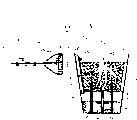
图2是图解本发明一种应用的简要示意图,其中本发明所述的方法用于更换鱼缸水;Fig. 2 is a schematic diagram illustrating an application of the present invention, wherein the method of the present invention is used for changing fish tank water;

图3是图解本发明另一个应用的简要示意图,其中根据本发明一个实施例本发明所述的方法用于给盆栽植物浇水;Fig. 3 is a schematic diagram illustrating another application of the present invention, wherein the method according to the present invention is used for watering potted plants according to an embodiment of the present invention;

图3a是简要示意图的顶视图,图示了根据本发明另一个实施例用于给盆栽植物浇水的本发明所述的方法;Figure 3a is a top view of a schematic diagram illustrating the method of the present invention for watering potted plants according to another embodiment of the present invention;

图3b是简要示意图的剖面图,图示了用于从图3a中图解的盆中抽取过剩水的本发明所述的方法;Figure 3b is a cross-sectional view of a schematic diagram illustrating the method of the present invention for extracting excess water from the basin illustrated in Figure 3a;

图4是在本发明一个实施例中使用的遥控器的透视图;Figure 4 is a perspective view of a remote control used in one embodiment of the invention;

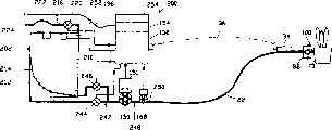
图5是根据本发明又一实施例所述的中央水流和排水系统的示意图;Fig. 5 is a schematic diagram of a central water flow and drainage system according to yet another embodiment of the present invention;

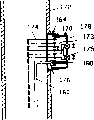
图6是图解水电连接器的示意图,它的指示器盖附着在其上;Figure 6 is a schematic diagram illustrating the hydroelectric connector with its indicator cover attached thereto;

图7是图解图6所示水电连接器的简要示意图,它的指示器盖被拆除并且处于连接状态;Fig. 7 is a schematic diagram illustrating the water and electricity connector shown in Fig. 6 with its indicator cover removed and in a connected state;

图8是图解根据本发明又一实施例所述的可连接水流和排水系统的简要示意图;Figure 8 is a schematic diagram illustrating a connectable water flow and drainage system according to yet another embodiment of the present invention;

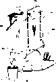
图9是图解根据本发明再一实施例所述的便携式水流和排水系统的简要示意图;Figure 9 is a schematic diagram illustrating a portable water flow and drainage system according to yet another embodiment of the present invention;

图10是图9所示便携式水流和排水系统的透视图;Figure 10 is a perspective view of the portable water flow and drainage system shown in Figure 9;

图10a是安装在图9所示便携式水流和排水系统中的触点安全阀的剖视图;Figure 10a is a cross-sectional view of the contact safety valve installed in the portable water flow and drainage system shown in Figure 9;

图10b是图10a所示触点安全阀的剖视图,图示了其垂直位置。Figure 10b is a cross-sectional view of the contact safety valve shown in Figure 10a, illustrating its vertical position.

具体实施方式Detailed ways

参考这些附图,尤其是图1,从原理上图解的并且通常用数字20表示的、用于供水和抽水的水流和排水系统包括单根水管22。水管22的一端24适合于与用户装置26一起使用,用于给其供水或从其抽水。相对于用户装置26的水管22的远端28连接到水电系统30,水电系统30也包括水源和用于排水的地方。水电系统30也电连接到主控制器32,以便在不同时期期间通过单根水管可以将所需量的水提供给用户装置26和从用户装置26中抽回。在运行期间,主控制器32给水电系统30发送信号,以便在远端28处在第一水流通模式和第二水流通模式之间切换水管22的水流通模式。在第一水流通模式中,水管22与水源进行流体流通,在第二水流通模式中,水管22与用于排水的地方进行流体流通。主控制器32也给水电系统30发送信号,以便例如依靠与可逆电机结合的泵,在两端24和28之间的水管22内产生流体压差,使得水从任一方向流入水管22。通过反转受主控制器32控制的电机,可以在供水和抽水之间选择水压模式。通过在水电系统30中装配两个泵可以代替与可逆电机结合的泵,其中一个泵通过水管22将水抽入用户装置26,而另一个泵通过水管22将水抽出用户装置26并将水输送进用于排水的地方。这两个泵也由主控制器32控制。Referring to these drawings, and in particular to FIG. 1 , the water flow and drainage system for water supply and pumping, schematically illustrated and generally indicated by the numeral 20 , comprises a single water pipe 22 . One end 24 of the water tube 22 is adapted for use with a user device 26 for supplying or drawing water therefrom. The distal end 28 of the water pipe 22 relative to the user unit 26 is connected to a hydroelectric system 30 which also includes a water source and a place for drainage. The hydroelectric system 30 is also electrically connected to the main controller 32 so that the desired amount of water can be supplied to and withdrawn from the user device 26 during different periods of time through a single water pipe. During operation, master controller 32 sends a signal to hydroelectric system 30 to switch the water flow mode of water pipe 22 at remote end 28 between a first water flow mode and a second water flow mode. In the first water circulation mode, the water pipe 22 is in fluid communication with a water source, and in the second water circulation mode, the water pipe 22 is in fluid communication with a place for draining water. Master controller 32 also sends signals to hydroelectric system 30 to create a fluid pressure differential in water pipe 22 between ends 24 and 28 to allow water to flow into water pipe 22 from either direction, for example by means of a pump in combination with a reversible motor. By reversing the motor controlled by the main controller 32, the water pressure mode can be selected between water supply and water pumping. The pump combined with the reversible motor can be replaced by having two pumps in the hydroelectric system 30, one of which pumps water into the consumer unit 26 through the water pipe 22, and the other pumps the water out of the consumer unit 26 through the water pipe 22 and delivers the water into a place for drainage. These two pumps are also controlled by the master controller 32 .

可以手动操作主控制器32给水电系统30发送信号,以便在同一时间从水源给用户装置26供应所需量的水,以及给水电系统30发送信号,以便在另一时间从用户装置26抽出所需量的水并将所需量的水输送到用于排水的地方。然而,也可以由主控制器32响应于从遥控器34中发送的信号自动执行这种操作,遥控器34位于用户装置26附近。要么如虚线36所示无线地、要么如虚线38所示通过电缆把遥控器34电连接到主控制器32。主控制器32也可以通过如虚线40所示的、连接到用户装置26的导线从与用户装置26结合的传感器(未图示)中接收信号。电缆38和导线40可以彼此直接连接而不需要通过遥控器34。在这种布置中,在遥控器34上手动启动供水和排水过程,根据保存在主控制器32或遥控器34中的预定程序,响应于从用户装置26的传感器中发送的信号逐步自动地实施这些过程,直到过程结束。The master controller 32 can be manually operated to signal the hydro system 30 to supply the required amount of water from the water source to the user device 26 at the same time, and to signal the hydro system 30 to draw all the water from the user device 26 at another time. The required amount of water and the required amount of water is delivered to the place for drainage. However, this operation may also be performed automatically by the main controller 32 in response to a signal sent from a remote control 34 located in the vicinity of the user device 26 . The remote control 34 is electrically connected to the main controller 32 either wirelessly as shown by the dashed line 36 or by a cable as shown by the dashed line 38 . The main controller 32 may also receive signals from sensors (not shown) associated with the user device 26 via wires connected to the user device 26 as indicated by dashed line 40 . The cable 38 and wire 40 can be directly connected to each other without going through the remote control 34 . In this arrangement, the water supply and drain process is initiated manually on the remote control 34, and is carried out automatically step by step in response to signals sent from sensors in the user unit 26 according to a predetermined program stored in the main controller 32 or the remote control 34. These processes until the end of the process.

为了理解根据本发明所述供水和排水方法所需条件的复杂性,并为了图解本发明的各种设备,下面描述不同类型的用户装置。要说明的是,根据本发明所述的各种应用和实施例,在附图的不同图中同样的附图标记用来表示本发明的类似部件和特征。因此,将不重复描述类似部件和特征。In order to understand the complexity of the conditions required for the water supply and drainage method according to the present invention, and to illustrate the various devices of the present invention, different types of user devices are described below. It is to be noted that like reference numerals are used in the different views of the drawings to refer to like parts and features of the invention according to various applications and embodiments of the invention described herein. Accordingly, descriptions of similar components and features will not be repeated.

图2图解的用户装置26A是鱼缸42,使用连接到水流和排水系统20的管22上的吸管44对其进行清洗。当第一次用水流和排水系统20对鱼缸42进行服务时,必须对系统20进行编程。The user device 26A illustrated in FIG. 2 is a fish tank 42 which is cleaned using a suction tube 44 connected to the pipe 22 of the water flow and drainage system 20 . When the aquarium 42 is serviced with the water flow and drainage system 20 for the first time, the system 20 must be programmed.

参考图1和4,使用图4中详细图解的遥控器34可以实施编程。为了编写鱼缸42的清洗程序,按遥控器34的键盘45上的“program(编程)”键46,然后重复按“user(用户)”键48,直到“aquarium(鱼缸)”显示在遥控器34的显示屏50上。如果系统20对一个以上鱼缸进行服务时,则遥控器34将显示用户装置名称和标志符,例如“鱼缸2”。主控制器32用名称“aquarium(鱼缸)”创建文件。然后将吸管44插入鱼缸42水中,按遥控器34的键盘45上的键52,开始从鱼缸42中抽水。当主控制器32响应于按下“drain(排水)”键52而从遥控器34发送的抽水信号而启动水电系统30时,水电系统30在管22中产生真空,通过吸管44的端部从鱼缸42中抽水。使用按遥控器34的键盘45上的“up(向上)”键54和“down(向下)”56可以调节抽水速度。适当选择的抽水速度将鱼缸42底部上的砂砾58中的沉积物与所抽的水一起升起,但基本上上将不打乱砂砾58。Referring to Figures 1 and 4, programming may be performed using the remote control 34 illustrated in detail in Figure 4 . In order to write the cleaning program of the fish tank 42, press the "program (programming)" key 46 on the keyboard 45 of the remote controller 34, then repeatedly press the "user (user)" key 48 until "aquarium (fish tank)" is displayed on the remote controller 34 on the display screen 50. If the system 20 is servicing more than one aquarium, the remote control 34 will display the user device name and identifier, eg "Aquarium 2". The main controller 32 creates a file with the name "aquarium". Suction pipe 44 is inserted in fish tank 42 water then, presses key 52 on the keyboard 45 of remote controller 34, starts to draw water from fish tank 42. When the main controller 32 activates the hydroelectric system 30 in response to the pumping signal sent from the remote control 34 by pressing the "drain (drainage)" key 52, the hydroelectric system 30 creates a vacuum in the tube 22, which draws water from the fish tank through the end of the suction tube 44. 42 in pumping. The pumping speed can be adjusted by pressing the "up" key 54 and "down" 56 on the keypad 45 of the remote control 34. A properly chosen pumping speed will lift sediment in the gravel 58 on the bottom of the fish tank 42 with the pumped water, but will not substantially disturb the gravel 58 .

当已经从鱼缸42中抽出所需量的水,按遥控器34的键盘45上的键60,终止排水时间。作为选择,可以简单地将吸管44从鱼缸42中的水中移开,使得抽水时间段结束。水电系统中的水流量计不再检测水,并给主控制器32发送信号,几秒钟后,主控制器32将切断水管22中的真空。When the desired amount of water has been drawn from the fish tank 42, press key 60 on the keypad 45 of the remote control 34 to terminate the draining time. Alternatively, the suction tube 44 may simply be removed from the water in the fish tank 42 so that the pumping period ends. The water flow meter in the hydropower system no longer detects water, and sends a signal to the main controller 32, and after a few seconds, the main controller 32 will cut off the vacuum in the water pipe 22.

从鱼缸42中已经抽出的水量和抽水速度保存在主控制器32中的为这个具体鱼缸42所创建的文件中。The amount of water that has been extracted from the fish tank 42 and the pumping speed are saved in the file created for this specific fish tank 42 in the main controller 32 .

为了在清洗鱼缸42之后开始给鱼缸42再充水,按下“water(充水)”键62启动水电系统30,以所选温度给鱼缸42供应需求量的淡水,通过按遥控器34的键盘45上的“temperature(温度)”键64可以调节所述温度,而且根据目前保存在文件中的数据,将水流设定到最大。当想要改变水流速时,可以按“up(向上)”键54和“down(向下)”56调节水流速。当与从鱼缸42中抽出的水量相同的水量已经供应给鱼缸42时,供水时间完成并终止。将调节的流速数据保存在该鱼缸文件中。In order to start to refill the fish tank 42 after cleaning the fish tank 42, press the "water (water filling)" key 62 to start the hydroelectric system 30, supply the required amount of fresh water to the fish tank 42 with the selected temperature, and press the keyboard of the remote control 34 The "temperature (temperature)" key 64 on 45 can adjust the temperature and set the water flow to the maximum according to the data currently saved in the file. When wanting to change the water flow rate, you can press "up (up)" key 54 and "down (down)" 56 to adjust the water flow rate. When the same amount of water as that drawn from the fish tank 42 has been supplied to the fish tank 42, the water supply time is completed and terminated. Save the adjusted flow rate data in this fish tank file.

在结束这个第一操作之前,遥控器34将通过它的显示屏50请求警报输入数据,然后为了设定所述警报,可以输入用于下一次清洗操作的预定日期。每日监控保存在主控制器32中的所有用户装置文件。当任何用户装置具有到期的服务期时,系统20的主控制器32将以蜂鸣器或指示灯的形式产生警报。Before concluding this first operation, the remote control 34 will request via its display 50 the alarm input data, and then, in order to set said alarm, the scheduled date for the next cleaning operation can be entered. All user device files stored in the main controller 32 are monitored daily. The main controller 32 of the system 20 will generate an alarm in the form of a buzzer or indicator light when any user device has an expired service period.

一旦具体用户装置的文件已经保存在系统20的主控制器32中,在这个应用中用户装置是鱼缸42,水流和排水系统20可以被自动用在鱼缸42的未来清洗操作中。为了启动自动操作,通过按遥控器34的键盘45上的“user(用户)”键48,选择鱼缸42作为用户装置,然后按下“drain(排水)”键52。将吸管44插入鱼缸42,将水连同砂砾58上的沉积物一起抽出鱼缸42。以预先编程的排水速度从鱼缸42中抽出水和沉积物,当从鱼缸42中抽出的水量达到根据保存在该鱼缸文件中的数据的量时,将自动切断排水时间段。预定的短时间间隔之后,将以保存在文件中的温度和速度自动供应淡水。当实施编程时,例如通过按遥控器34的键盘45上的功能键66,可以调节排水时间和供水时间之间的预定短时间间隔。当根据保存在主控制器32文件中的数据补充了所需量的水时,主控制器32将自动关闭水流和排水系统20。Once the file for a specific user device, in this application the fish tank 42, has been saved in the master controller 32 of the system 20, the water flow and drainage system 20 can be automatically used in future cleaning operations of the fish tank 42. To initiate automatic operation, select the fish tank 42 as the user device by pressing the "user" key 48 on the keypad 45 of the remote control 34, and then press the "drain" key 52. The suction tube 44 is inserted into the fish tank 42 and the water is drawn out of the fish tank 42 along with the sediment on the gravel 58 . Water and sediment are drawn from the tank 42 at a pre-programmed drain rate, and when the amount of water drawn from the tank 42 reaches an amount according to data stored in the tank file, the drain period is automatically cut off. After a predetermined short interval, fresh water is automatically supplied at the temperature and speed saved in the file. When programming is performed, for example by pressing a function key 66 on the keypad 45 of the remote control 34, the predetermined short time interval between the drain time and the water supply time can be adjusted. When the required amount of water is replenished according to the data stored in the main controller 32 file, the main controller 32 will automatically shut down the water flow and drainage system 20 .

要说明的是,遥控器34在其背面设有一对固定件68,固定件便于允许遥控器34在沿软水管22长度的任何位置上可分离地连接到其上。It should be noted that the remote control 34 is provided with a pair of fixing members 68 on its back side, which are convenient for allowing the remote control 34 to be detachably connected thereto at any position along the length of the hose 22 .

参考图1和3,下面描述水流和排水系统20的另一种应用。在这种应用中,与水流和排水系统20一起使用的用户装置26B是植物盆70,为了延长浇水间的时间,准备使用储存水的蓄水池88进行自动浇水。这个应用产生于给有根植物浇水的方法,所述根位于无排水孔的盆中的土壤中,在申请人的美国专利申请NO.09/945620中描述了这种方法。在该美国专利申请中描述的方法包括以下步骤:通过由不渗水材料形成的水通道,在压力下将水引入盆底,从盆底向上延伸并伸出盆,直到水淹没盆中土壤顶部;然后通过相同通道,从盆中排除未被土壤吸收的部分水。优选地在盆底和土壤底部之间提供空间,该空间适合于收集从土壤中排出的水并与通道进行流体流通。Referring to Figures 1 and 3, another application of the water flow and drainage system 20 is described below. In this application, the user device 26B used with the water flow and drainage system 20 is a plant pot 70 ready to be watered automatically using a reservoir 88 for storing water for extended time between waterings. This application arose from the method of watering rooted plants in soil in non-drainage pots, which is described in Applicant's US Patent Application No. 09/945620. The method described in this US patent application comprises the steps of introducing water under pressure into the bottom of the pot through a water channel formed of impermeable material, extending from the bottom of the pot up and out of the pot until the water covers the top of the soil in the pot; The portion of the water not absorbed by the soil is then drained from the pot through the same channel. A space is preferably provided between the pot floor and the soil bottom, the space being adapted to collect water drained from the soil and to be in fluid communication with the channel.

植物盆70包括开口顶部72、封闭底部74和侧壁76,侧壁在顶部72和底部74之间延伸成截锥形。穿孔挡板78将植物盆70分割成上部分和下部分。上部分用于容纳土壤80,植物根掩埋在土壤中。下部分形成为蓄水池82,用于容纳植物盆70中的水。穿孔挡板78容许水向下或向上自由地穿过它,而禁止土壤颗粒落入蓄水池82。管84从蓄水池82延伸接近植物盆70的底部74,穿过穿孔挡板78并沿侧壁76向上延伸。管84的上端伸出植物盆70的开口顶部72,并利用水流和排水系统20的水电连接器86和植物盆70的水电插座100连接到水流和排水系统20的水管22上。The plant pot 70 includes an open top 72 , a closed bottom 74 and side walls 76 extending between the top 72 and the bottom 74 in a frusto-conical shape. A perforated baffle 78 divides the plant pot 70 into upper and lower sections. The upper part is used to hold the soil 80 in which the plant roots are buried. The lower portion is formed as a water reservoir 82 for containing water in the plant pot 70 . The perforated barrier 78 allows water to pass freely through it downwardly or upwardly while inhibiting soil particles from falling into the reservoir 82 . A tube 84 extends from the reservoir 82 proximate the bottom 74 of the plant pot 70 , through the perforated baffle 78 and up the side wall 76 . The upper end of the tube 84 protrudes from the open top 72 of the plant pot 70 and is connected to the water pipe 22 of the water flow and drainage system 20 using the water connector 86 of the water flow and drainage system 20 and the water socket 100 of the plant pot 70 .

开关88和90分别位于蓄水池82的顶部和底部,它们中的每个由浮动件92启动。水位检测器94位于植物盆70中的土壤80顶部,通过接触水来启动它。通过电缆102、水电连接器86和电缆96,开关88、90和检测器94连接到遥控器34,该检测器94作用为水位传感器。Switches 88 and 90 are located at the top and bottom of reservoir 82 respectively, each of which is actuated by float 92 . A water level detector 94 is located on top of the soil 80 in the plant pot 70 and is activated by contact with water. The switches 88, 90 and detector 94, which acts as a water level sensor, are connected to the remote control 34 via the cable 102, the water connector 86 and the cable 96.

水电连接器86连接到软水管22和信号导线38,根据与装置26一起使用的传感器类型,信号导线38可以是光纤。然而,在本发明的这个实施例中,导线38是电线。优选地电线38组合在软水管22的壁中,以便电线38得到保护并可以与软水管22一起被方便地移动。水电插座100连接到管84和电线102的外端,电线102与各个传感器88、90和94电连接。遥控器34和水电连接器86之间的电缆96是可选择的,因为遥控器34无线连接到主控制器32,主控制器32通过电线38依次连接到水电连接器86。当水电连接器86和水电插座100连接在一起时,电缆102利用金属触点(未指示)连接到各自的电缆96和电线38,而且连接管84与管22流体相通。A water connector 86 connects to the water hose 22 and to a signal lead 38 which may be an optical fiber depending on the type of sensor used with the device 26 . However, in this embodiment of the invention, the conductors 38 are wires. The electrical wires 38 are preferably incorporated in the wall of the hose 22 so that the electrical wires 38 are protected and can be conveniently moved along with the hose 22 . A water receptacle 100 is connected to the outer ends of the tube 84 and an electrical wire 102 electrically connected to each of the sensors 88 , 90 and 94 . The cable 96 between the remote control 34 and the water connector 86 is optional because the remote control 34 is wirelessly connected to the main controller 32 which in turn is connected to the water connector 86 by the wire 38 . When the water connector 86 and the water receptacle 100 are connected together, the cable 102 is connected to the respective cable 96 and wire 38 using metal contacts (not indicated), and the connection tube 84 is in fluid communication with the tube 22 .

水电插座100包括存储器芯片104。遥控器34直接或通过主控制器32可以读取存储器芯片104的数据,但是遥控器34不能改变该数据。对存储器芯片104进行编程以用于具体植物盆70,存储器芯片104包含标识号以及代码,优选地标识号任意选择为高数字,代码包括自动浇水所需的所有其它数据。The utility socket 100 includes a memory chip 104 . The remote control 34 can read the data of the memory chip 104 directly or through the main controller 32, but the remote control 34 cannot change the data. The memory chip 104 is programmed for a particular plant pot 70 and contains an identification number, preferably arbitrarily chosen as a high number, along with a code that includes all other data required for automatic watering.

当水电连接器86和水电插座100第一次连接在一起时,遥控器34读取保存在存储器芯片104中的标识号并将其发送到主控制器32,或者主控制器32直接读取标识号。主控制器32将该数字与保存在系统20中的其它标识号进行比较,并因为读取的标识号不能与已经保存在系统20中的任一标识号相匹配,则继续为读取的用户装置26B的标识号创建新文件。主控制器32为植物盆70确定默认数字,例如“花盆8”,以便显示在遥控器34的显示屏50上(参见图4)。如果需要,可以对所显示的植物盆70的默认数字进行修改。然后建议将标签或标记(未图示)粘贴到表示该数字的植物盆70,字符和/或名称分配给该具体植物盆70。现在将存储器芯片104中的其它数据保存在用植物盆70的具体标识号创建的文件中。When the water and electricity connector 86 and the water and electricity socket 100 were connected together for the first time, the remote controller 34 read the identification number stored in the memory chip 104 and sent it to the main controller 32, or the main controller 32 directly read the identification Number. The master controller 32 compares this number with other identification numbers stored in the system 20, and because the read identification number cannot match any identification number already stored in the system 20, the user who continues to read The identification number of device 26B creates a new file. The master controller 32 determines a default number for the plant pot 70, such as "pot 8", for display on the display screen 50 of the remote control 34 (see FIG. 4). The default number of plant pots 70 shown can be modified if desired. It is then suggested that a label or label (not shown) be affixed to the plant pot 70 representing the number, letter and/or name assigned to that particular plant pot 70 . The other data in the memory chip 104 is now saved in a file created with the specific identification number of the plant pot 70 .

水流和排水系统20与植物盆70连接之后,可以手动或自动启动供水和排水过程,因为主控制器32提供利用从存储器芯片104中读取的参数预先编写的程序。启动供水和排水过程之后,主控制器32通过软水管22以预置速度打开水流,以便使用淹没和排水浇水方法对盆栽植物进行浇水。通过管84将水输入植物盆70的蓄水池82中。当蓄水池82中的水上升浮动件92而启动蓄水池82顶部上的开关90时,降低水流速。然后通过管84以降低的速度连续将水供给植物盆70,以便用水淹没土壤80。当水位检测器94检测到水并发送信号给水流和排水系统20时,切断给植物盆70供水。After the water flow and drainage system 20 is connected to the plant pot 70 , the water supply and drainage process can be started manually or automatically because the main controller 32 provides a pre-programmed program using the parameters read from the memory chip 104 . After starting the water supply and drain process, the master controller 32 turns on the water flow through the hose 22 at a preset rate to water the potted plants using the flood and drain watering method. Water is fed into the reservoir 82 of the plant pot 70 via a pipe 84 . When the water in the reservoir 82 rises up the float 92 activating a switch 90 on the top of the reservoir 82, the water flow rate is reduced. Water is then continuously supplied to the plant pot 70 at a reduced rate through the pipe 84 so that the soil 80 is flooded with water. Water supply to plant pot 70 is shut off when water level detector 94 detects water and sends a signal to water flow and drainage system 20 .

切断给植物盆70供水之后几秒钟,水流和排水系统20通过软水管22和管84开始从植物盆70中抽水。当植物盆70中的水位降低到蓄水池82顶部之下时,使得浮动件92关闭开关90,水流和排水系统20停止从植物盆70中抽水。因此,植物盆70的蓄水池82包含水,以利用多个吸液芯部件106继续给植物盆70的土壤80提供一段时间的湿气,吸液芯部件106从蓄水池82向上延伸,越过穿孔挡板78,进入土壤80的下部,土壤80包含在植物盆70的上部中。A few seconds after the water supply to the plant pot 70 is cut off, the water flow and drainage system 20 begins to draw water from the plant pot 70 through the hose 22 and the tube 84 . When the water level in the plant pot 70 drops below the top of the reservoir 82 , causing the float 92 to close the switch 90 , the water flow and drainage system 20 stops pumping water from the plant pot 70 . Accordingly, the reservoir 82 of the plant pot 70 contains water to continue to provide moisture to the soil 80 of the plant pot 70 for a period of time utilizing a plurality of wick members 106 extending upwardly from the reservoir 82, Beyond the perforated barrier 78 , access is made to the lower portion of the soil 80 contained in the upper portion of the plant pot 70 .

在起始过程期间,观察供水和排水过程,如果需要,可以立即或在任何时刻进行调节。然后将调节值替换这个具体装置26B文件中的预定参数,在这个应用中具体装置是植物盆70。也测量从蓄水池82顶层到植物盆70开口端72处的水位的水量,这个数据记录在主控制器32的文件中,开关90位于蓄水池82顶层,水位检测器94位于植物盆70开口端。在水位检测器94发生故障的情况下,水量这个参数就随后用作预防备份数据,以便当启动开关90之后已经供应了预置水量时,虽然水位检测器94没有发送相应信号,水流和排水系统20也将自动关闭供水。由此消除水溢出植物盆70的可能。可以使用遥控器34将下一个计划服务日期输入水流和排水系统20。然后当到达计划服务日期时,主控制器32将检测警报。During the start-up process, the water supply and drain process is observed and, if necessary, adjusted immediately or at any time. The adjusted values are then substituted for the predetermined parameters in the file 26B for this particular device, which in this application is the plant pot 70 . Also measure the water quantity from the top floor of the reservoir 82 to the water level at the open end 72 of the plant pot 70, this data is recorded in the file of the master controller 32, the switch 90 is located at the top layer of the reservoir 82, and the water level detector 94 is positioned at the plant pot 70 open end. In the event of a failure of the water level detector 94, this parameter of water quantity is then used as a preventive backup data, so that when the preset water quantity has been supplied after actuating the switch 90, although the water level detector 94 does not send a corresponding signal, the water flow and drainage system 20 will also automatically shut off the water supply. The possibility of water overflowing the plant pot 70 is thereby eliminated. The next planned service date can be entered into the water flow and drainage system 20 using the remote control 34 . The master controller 32 will then detect the alarm when the scheduled service date is reached.

在下一个供水和排水服务中,当水电连接器86和插座100连接在一起而且保留在蓄水池82中的水维持浮动件90漂浮在蓄水池82底部上的开关88之上时,主控制器32将识别开关88的无效状态。这表示在蓄水池82中还存在剩下的水,将重写保存在主控制器32中的植物盆70的文件,使其在供水和排水服务过程之间具有更长时间间隔。In the next water supply and drainage service, when the water connector 86 and the socket 100 are connected together and the water remaining in the reservoir 82 maintains the float 90 floating above the switch 88 on the bottom of the reservoir 82, the main control The device 32 will recognize the inactive state of the switch 88. This indicates that there is still water remaining in the reservoir 82, and the file of the plant pot 70 stored in the main controller 32 will be overwritten to have a longer time interval between water supply and drain service processes.

现在参考图1和3a、3b。水流和排水系统20也可以用来手动给盆栽植物浇水。在手动操作中,水流和排水系统20可以用来给植物浇水,其生长在类似于植物盆70的植物盆中,专门设计这种植物盆来使用自底向上浇水的方法,但是如图3a和3b所示也可以用来给生长在目前市场上可用的植物盆中的植物浇水。与水流和排水系统20一起使用的装置26C包括植物盆106,其具有开口顶部108、封闭底部110和侧壁112,侧壁在顶部108和底部110之间延伸成截锥形。盘116位于植物盆106底部110之下,用于收集通过一个或多个排水孔114从土壤80中排出的黑水,排水孔114位于植物盆106的封闭底部110中。Reference is now made to Figures 1 and 3a, 3b. The water flow and drainage system 20 can also be used to manually water potted plants. In manual operation, the water flow and drainage system 20 can be used to water plants, which are grown in plant pots similar to plant pots 70, which are specially designed to use bottom-up watering methods, but as shown 3a and 3b can also be used to water plants growing in plant pots currently available on the market. Apparatus 26C for use with water flow and drainage system 20 includes plant pot 106 having open top 108 , closed bottom 110 and side walls 112 extending between top 108 and bottom 110 in a frusto-conical shape. A pan 116 is located below the bottom 110 of the plant pot 106 for collecting black water that drains from the soil 80 through one or more drainage holes 114 located in the closed bottom 110 of the plant pot 106 .

取代图3的水电连接器86,具有扁平出口的适配器118连接到水流和排水系统20的软水管22。在手动操作中,使用水流和排水系统20的遥控器34手动开始供水时间。适配器118位于植物盆106开口顶部108之上,以便将由水流和排水系统20提供的水流通过适配器118输送给土壤80顶部。从植物盆106开口顶部108输入植物盆106的水蔓延,并被土壤80吸收,同时通过排水孔114顺流而下进入盘116。一旦在盘116中观察到黑水,立即手动终止水流和排水系统20的供水时间段。盘116需要较短时间收集从植物盆106的土壤80中排出的所有黑水,然后为了开始排水时间段,将适配器118的扁平出口放入盘116中的黑水中,也可以使用水流和排水系统20的遥控器34手动启动排水时间段。当在盘116中没有留下黑水时,可以使用遥控器34手动终止排水时间段。作为选择,当检测到软水管22中的无水状态时,水流和排水系统20可以自动关闭。Instead of the water connector 86 of FIG. 3 , an adapter 118 with a flat outlet connects to the hose 22 of the water flow and drainage system 20 . In manual operation, the water supply time is manually started using the remote control 34 of the water flow and drainage system 20 . The adapter 118 is positioned above the open top 108 of the plant pot 106 so that the water flow provided by the water flow and drainage system 20 is delivered through the adapter 118 to the top of the soil 80 . Water entering the plant pot 106 from the open top 108 of the plant pot 106 spreads, is absorbed by the soil 80 , and flows downstream through the drainage holes 114 into the tray 116 . As soon as black water is observed in the pan 116, the water flow and the water supply period of the drainage system 20 are immediately manually terminated. The pan 116 takes a short time to collect all the black water that drains from the soil 80 of the plant pot 106, then to start the drainage period, place the flat outlet of the adapter 118 into the black water in the pan 116, a water flow and drainage system can also be used The remote control 34 of 20 manually starts the drainage time period. The drain period can be manually terminated using the remote control 34 when no black water is left in the pan 116 . Alternatively, the water flow and drainage system 20 may be automatically shut off when a dry condition in the hose 22 is detected.

如果供水时间段期间的水流速相对高,并且盘116中收集的黑水快速增长到接近盘116的顶部边缘的水位,为了防止水溢出盘116,供水时间段终止之后,排水时间段可能必须立即开始。If the water flow rate during the water supply period is relatively high, and the black water collected in the pan 116 grows rapidly to a level near the top edge of the pan 116, in order to prevent the water from overflowing the pan 116, the drain period may have to be drained immediately after the water supply period ends. start.

参考图2、3、3a、3b描述的应用只是使用本发明方法和系统的实例,参考图1对本发明进行描述。能够与本发明一起使用的更多应用可以得到进一步认可。例如图1的水流和排水系统20可以与专门设计的地板清洁设备一起使用,该设备在压力下将水喷洒在地板表面上进行清洗,在不同的时段期间,用真空吸尘器打扫地板表面中的黑水。专门设计的地板清洁设备不是本发明的部分,因此将不进一步描述它。The applications described with reference to Figures 2, 3, 3a, 3b are only examples of the use of the method and system of the invention, the invention being described with reference to Figure 1 . Further applications that can be used with the present invention may be further recognized. For example, the water flow and drainage system 20 of FIG. 1 may be used with specially designed floor cleaning equipment that sprays water under pressure onto the floor surface for cleaning, and during various periods of time, vacuums the floor surface to remove black dirt. water. A specially designed floor cleaning device is not part of the present invention, so it will not be described further.

图5图解了中央水流和排水系统,一般用数字130表示。图解的中央水流和排水系统130用来与多个植物盆一起使用,这些植物盆与参考图3所述的植物盆70的类型相同。应该理解,在上述各种应用中各种装置可以与中央水流和排水系统130一起使用。FIG. 5 illustrates the central water flow and drainage system, indicated generally at 130 . The illustrated central water flow and drainage system 130 is intended for use with plant pots of the same type as the plant pots 70 described with reference to FIG. 3 . It should be understood that various devices may be used with the central water flow and drainage system 130 in the various applications described above.

中央水流和排水系统130包括总管系统132,例如,优选地其布置在配备有水流和排水系统130的房子地下室中。总管系统132通过电磁阀134连接到水源,进行流体流通。水源是低压水罐136,其通过电磁阀138和140分别连接到冷水补给线和热水补给线。总管系统132通过电磁阀142和144也分别直接和利用辅助收集器148间接连接到排水入口146。辅助收集器148是可选择的。总管系统132还连接到泵150,其耦合到可逆电机151并适合由可逆电机151驱动。优选地,低压水罐136放置在地下室中,而辅助收集器148可以放置在室外。The central water flow and drainage system 130 includes a mains system 132 , eg preferably arranged in the basement of a house equipped with the water flow and drainage system 130 . The mains system 132 is connected to a water source via a solenoid valve 134 for fluid communication. The water source is a low pressure water tank 136, which is connected to the cold and hot water supply lines through solenoid valves 138 and 140, respectively. The header system 132 is also connected directly to the drain inlet 146 through solenoid valves 142 and 144 and indirectly with an auxiliary collector 148, respectively. Auxiliary collector 148 is optional. The manifold system 132 is also connected to a pump 150 which is coupled to and suitably driven by a reversible motor 151 . Preferably, the low pressure water tank 136 is placed in the basement, while the auxiliary collector 148 can be placed outside.

优选地,在地下室中也提供主控制器单元152和电源单元154,它们连接到地下室中的电气系统中。主控制器单元152电连接到电磁阀134、138、140、142和144。主控制器单元152也电连接到电机151,以及安装在低压水罐136上的压力传感器156和温度传感器158,分别用于测量罐136的内压和水温。Preferably, a main controller unit 152 and a power supply unit 154 are also provided in the basement, which are connected to the electrical system in the basement. The main controller unit 152 is electrically connected to the solenoid valves 134 , 138 , 140 , 142 and 144 . The main controller unit 152 is also electrically connected to the motor 151, and a pressure sensor 156 and a temperature sensor 158 mounted on the low-pressure water tank 136 for measuring the internal pressure and water temperature of the tank 136, respectively.

水流和排水系统130配备有配水网160,配水网160包含连接在一起的水管路部分。配水网160在它的一个开口处连接到泵150,而在另一个开口处利用水电连接器162选择连接到软水管22,下文中将参考图6和7详细描述水电连接器162。用于连接软水管22的这些配水网160的开口可以连接到室内浇水出口164,这些出口164固定在房子各个位置上的墙内和不同地板上。配水网160在房子外面可以进一步包括一个或多个开口,所述开口由手控阀166控制用来有选择地连接房子外面的软水管22。水流量计168包含在靠近泵150的配水网160中,以便当水流经配水网160时,将测量水量,而不管连接软水管22的出口164的选择情况。The water flow and drainage system 130 is equipped with a water distribution network 160 comprising water pipe sections connected together. The water distribution grid 160 is connected at one of its openings to the pump 150 and at the other opening is optionally connected to the hose 22 by means of a water and electricity connector 162 which will be described in detail below with reference to FIGS. 6 and 7 . The openings of these water distribution networks 160 for connection of hoses 22 can be connected to indoor watering outlets 164 fixed in walls and on different floors at various places in the house. The water distribution network 160 may further include one or more openings outside the house controlled by a manual valve 166 for selectively connecting the water hose 22 outside the house. A water flow meter 168 is included in the water distribution network 160 close to the pump 150 so that as water flows through the water distribution network 160 the amount of water will be measured regardless of the selection of the outlet 164 connected to the hose 22 .

主控制器单元152电连接到水流量计168,以便接收表示测量水流量的电信号。还提供电线,以将主控制器单元152与房子各个位置上和不同地板上的室内浇水出口164连接,用于双向传输电信号,下文中将进一步对此进行详细描述。The main controller unit 152 is electrically connected to the water flow meter 168 to receive an electrical signal indicative of the measured water flow. Wires are also provided to connect the main controller unit 152 with indoor watering outlets 164 at various locations in the house and on different floors for bi-directional transmission of electrical signals, as will be described in further detail below.

在图6中室内浇水出口164由盖170保护。室内浇水出口164适合于固定在内墙172中,具有许多电触点174和一个开口176,电触点174通过电线连接到图5所示的主控制器单元152,开口176与配水网160的一个管路部分进行流体流通。为了防止盖170被意外地出口164移开,盖170包括机械联锁件178,以便与出口164的相应部分进行联锁。当盖170与出口164联锁时,为了防止漏水,插头180与盖170装备在一起来密封封闭开口176,插头180容纳在开口176中。盖170也包括短路173和指示器灯175,当盖170固定到出口164时,指示器灯175与出口164的相应触点电接触,以便当这个出口被盖上时,图5的主控制器单元152识别出口164没有使用。指示器灯175可以包括用于“system in use(系统使用中)”的指示器和用于“alarm(警报)”的指示器,当图5的水流和排水系统130通过另一个出口164运行时,用于“system in use(系统使用中)”的指示器变亮,当浇水操作的预定日期到达时,用于“警报”的指示器变亮。也可以在盖170中安装任意蜂鸣器(未图示),以便当“alarm(警报)”指示器变亮时,产生声音警报。The indoor watering outlet 164 is protected by a cover 170 in FIG. 6 . The indoor watering outlet 164 is adapted to be fixed in the interior wall 172 and has a number of electrical contacts 174 and an opening 176 which is wired to the main controller unit 152 shown in FIG. One part of the pipeline for fluid communication. To prevent cover 170 from being accidentally removed by outlet 164 , cover 170 includes a mechanical interlock 178 for interlocking with a corresponding portion of outlet 164 . When the cover 170 is interlocked with the outlet 164, in order to prevent water leakage, a plug 180 is equipped with the cover 170 to hermetically close the opening 176 in which the plug 180 is accommodated. The cover 170 also includes a short circuit 173 and an indicator light 175 which, when the cover 170 is secured to the outlet 164, makes electrical contact with the corresponding contacts of the outlet 164 so that when this outlet is covered, the main controller of FIG. 5 Unit 152 identifies that outlet 164 is not used. Indicator light 175 may include an indicator for "system in use" and an indicator for "alarm" when the water flow and drainage system 130 of FIG. , the indicator for "system in use" lights up, and the indicator for "alarm" lights up when the scheduled date for the watering operation arrives. An optional buzzer (not shown) may also be installed in the cover 170 to generate an audible alarm when the "alarm" indicator is illuminated.

通过挤压并将盖170拉出可以移开它。一旦将盖170已经从出口164移开,如图7所示,通过水电连接器162可以将软水管22连接到出口164。为了与出口164的相应部件进行联锁,以便连接器162能够可释放地固定到出口164,类似于盖170的机械联锁件178,水电连接器162具有机械联锁件182。水电连接器162连接到软水管22的一端,该端未连接到水电连接器86(参见图5),当水电系统连接器162固定到出口164时,它提供软水管22和配水网160的一个管路部分的防水连接。当水电连接器162连接到出口164时,与软水管22组合在一起的电线38连接到提供与出口164的触点174电连接的水电连接器162的触点(未指示),以使从图5所示的植物盆70中发送的信号通过这种连接传输给图5所示的主控制器单元152。作为盖170内的短路172的替代方案,在水电连接器162中提供电阻器184,它适合于与触点174接触,这些触点174包含在出口164内,并被设计成与盖170的短路172接触。因此,当水电连接器162连接到这个具体出口164时,主控制器单元152(图5)可以识别出其中一个出口164在操作中被使用。只有当图5的主控制器单元152检测到其中一个盖170被移开并且软水管22连接到这个具体出口164时,对图5的水流和排水系统130进行编程,允许浇水操作。因而,减少了误操作的可能性,由此水溢出风险得到最小化。Cover 170 can be removed by squeezing and pulling it off. Once the cover 170 has been removed from the outlet 164 , the water hose 22 may be connected to the outlet 164 via the water connector 162 as shown in FIG. 7 . To interlock with corresponding components of the outlet 164 so that the connector 162 can be releasably secured thereto, the utility connector 162 has a mechanical interlock 182 similar to the mechanical interlock 178 of the cover 170 . The hydroelectric connector 162 is connected to one end of the soft water pipe 22 which is not connected to the hydroelectric connector 86 (see FIG. 5 ), and when the hydroelectric system connector 162 is fixed to the outlet 164, it provides a connection between the soft water pipe 22 and the water distribution network 160. Watertight connection of the piping section. When the water and electricity connector 162 is connected to the outlet 164, the electric wire 38 combined with the hose 22 is connected to a contact (not indicated) of the water and electricity connector 162 that provides an electrical connection with the contact 174 of the outlet 164, so that from FIG. The signal transmitted in the plant pot 70 shown in FIG. 5 is transmitted to the main controller unit 152 shown in FIG. 5 through this connection. As an alternative to the short circuit 172 in the cover 170, a resistor 184 is provided in the hydroelectric connector 162, which is adapted to make contact with the contacts 174 contained in the outlet 164 and designed to be a short circuit with the cover 170 172 contacts. Thus, when the hydro connector 162 is connected to this particular outlet 164, the main controller unit 152 (FIG. 5) can recognize that one of the outlets 164 is used in operation. The water flow and drainage system 130 of FIG. 5 is programmed to allow watering operations only when the main controller unit 152 of FIG. 5 detects that one of the covers 170 is removed and the hose 22 is connected to that particular outlet 164 . Thus, the possibility of mishandling is reduced, whereby the risk of water spillage is minimized.

再次参考图5,中央水流和排水系统130可以与室外出口165一起使用,室外出口165包括用于连接的螺纹插口。带有常规连接器的软管可以连接到室外出口165的常规螺纹插口。为了运行室外操作,必须按图4所示遥控器34的键盘45上的“user(用户)”键48,选择室外操作。一旦选择了室外操作,当所有室内出口164被盖住时,可以只启动供水和排水操作。室外操作开始时必须手动打开阀166,而室外操作结束之后,必须手动关闭阀166。也可以手动运行室外操作的供水和排水时间段。Referring again to FIG. 5, the central water flow and drainage system 130 may be used with an outdoor outlet 165 that includes a threaded socket for connection. A hose with a conventional connector can be connected to the conventional threaded socket of the outdoor outlet 165 . In order to run the outdoor operation, the "user" key 48 on the keypad 45 of the remote control 34 shown in FIG. 4 must be pressed to select the outdoor operation. Once outdoor operation is selected, water supply and drain operations may only be activated when all indoor outlets 164 are covered. Valve 166 must be manually opened when outdoor operation begins, and valve 166 must be manually closed after outdoor operation has ended. Water supply and drain time periods for outdoor operation can also be run manually.

在本发明的这个实施例中,通过瞬间接通电磁阀134,中央水流和排水系统130使用低压水罐136给泵150自动注水,因为大部分泵如果干时操作,将不能适当运行或遭到破坏。压力传感器156测量低压水罐136的内压,温度传感器158测量低压水罐136内的水温。主控制器单元152操作电磁阀134、138、140和142,以根据主控制器单元152内的文件确保水温正确和罐压位于所要求的范围内。例如,如果水温太低,主控制器单元152给电磁阀140发送信号打开它,允许热水流入低压水罐136。如果低压水罐136已将满了,温度还是太低,主控制器单元152给电磁阀140发送信号关闭它,然后为了从低压水罐136中排出所需量水,给电磁阀134和142发送信号打开它们,然后主控制器单元152给电磁阀134和142发送信号关闭它们,为了供应更多热水,给电磁阀140发送信号重新将其打开。In this embodiment of the invention, the central water flow and drainage system 130 uses the low pressure tank 136 to automatically prime the pump 150 by momentarily turning on the solenoid valve 134, since most pumps will not function properly or be damaged if operated dry. destroy. The pressure sensor 156 measures the internal pressure of the low-pressure water tank 136 , and the temperature sensor 158 measures the water temperature in the low-pressure water tank 136 . The main controller unit 152 operates the solenoid valves 134, 138, 140 and 142 to ensure that the water temperature is correct and the tank pressure is within the required range according to the files in the main controller unit 152. For example, if the water temperature is too low, the main controller unit 152 sends a signal to the solenoid valve 140 to open it, allowing hot water to flow into the low pressure tank 136 . If the low-pressure water tank 136 is almost full and the temperature is still too low, the main controller unit 152 sends a signal to the solenoid valve 140 to close it, and then sends a signal to the solenoid valves 134 and 142 in order to discharge the required amount of water from the low-pressure water tank 136. The signal opens them, then the main controller unit 152 sends a signal to the solenoid valves 134 and 142 to close them, and in order to supply more hot water, sends a signal to the solenoid valve 140 to open it again.

当使用遥控器34启动供水时间段时,遥控器34在接近植物盆70的端部按照在软水管22上,给电磁阀134发送信号启动它,电极151开始驱动泵150,将水从低压水罐136抽到植物盆70。泵150和与软水管22连接的所选室内出口164之间的配水网160分支与软水管22一起形成单个水通道,用于给植物盆70供水和从植物盆70中排水。由水流量计168测量供水时间段中的水流量,并将该信息传送给主控制器152,然后为了确保所需流速,主控制器152给电机151发送信号调节它的速度。When using the remote controller 34 to start the water supply time period, the remote controller 34 is pressed on the flexible water pipe 22 at the end close to the plant pot 70, and sends a signal to the solenoid valve 134 to start it, and the electrode 151 starts to drive the pump 150 to transfer water from the low-pressure water supply to the solenoid valve 134. Pot 136 pumps to plant pot 70 . The distribution network 160 branches between the pump 150 and selected indoor outlets 164 connected to the hose 22 together with the hose 22 to form a single water channel for supplying water to and draining the plant pot 70 . The water flow during the water supply period is measured by the water flow meter 168, and this information is sent to the main controller 152, and then in order to ensure the required flow rate, the main controller 152 sends a signal to the motor 151 to adjust its speed.

响应于在主控制器单元152中接收的停止信号,断开电机151、泵150、电磁阀134、138和140。当在主控制器单元152中接收到排水信号时,根据编写程序或信号,从遥控器34中手动发出所述信号,主控制器单元152接通电磁阀142,并在某一方向上启动电机151驱动泵150,以通过单个水通道从植物盆70中抽水,所述单个水通道用来给同一植物盆70供水。水流量计168测量排水流速,并将该值显示在遥控器34的显示面板上。水流量计168可以检测无水状态,并且当不再有水从植物盆70中被抽出时,在遥控器34的显示面板上显示“no-water(无水)”信息。然后,主控制器单元152切断电机151和泵150,并因此关闭电磁阀142。In response to a stop signal received in the main controller unit 152, the motor 151, the pump 150, the solenoid valves 134, 138 and 140 are turned off. When receiving the drainage signal in the main controller unit 152, according to the written program or signal, the signal is manually sent from the remote controller 34, the main controller unit 152 turns on the solenoid valve 142, and starts the motor 151 in a certain direction The pump 150 is driven to draw water from the plant pot 70 through a single water channel used to supply water to the same plant pot 70 . The water flow meter 168 measures the drainage flow rate and displays the value on the display panel of the remote controller 34 . The water flow meter 168 can detect a no-water condition and when no more water is being drawn from the plant pot 70, a "no-water" message is displayed on the display panel of the remote control 34. Then, the main controller unit 152 turns off the motor 151 and the pump 150, and thus closes the solenoid valve 142.

现在参考图4和5,通过按遥控器34键盘45上的键48,可以选择辅助收集器148收集排出水,遥控器34的显示屏50将显示“from:user to:auxiliary tank(从:用户 到:辅助罐)”。一旦选择了辅助收集器148,在排水时间期间将给电磁阀142发送信号关闭它,给电磁阀144发送信号打开它,以便将排出水引入和收集在辅助收集器148中。当辅助收集器148满了时,辅助收集器148中的排出水将自动流入排水口146。在其它应用中也可以使用辅助收集器148中收集的排出水。例如,通过连接到室外出口165的软管,从浴缸中排出并被收集在辅助收集器148中的水可以用于清洗车辆,或者从渔缸中排出并被收集在辅助收集器148中的水可以用于给盆栽植物70浇水。在这种情况下,必须选择辅助收集器148作为水源,通过按遥控器34键盘45上的“user(用户)”键48直到遥控器34的显示屏50显示“from:auxiliary tank to:user(从:辅助罐 到:用户)”来进行选择。当选择辅助收集器148作为水源时,主控制器单元152将接通电磁阀144,并且当启动供水时间段时断开其它阀。因而,电机151在某一方向上驱动泵150,以便通过所选配水网160的分支和软水管22将水从辅助收集器148中抽到植物盆70中。Referring now to Figures 4 and 5, by pressing the key 48 on the keyboard 45 of the remote control 34, the auxiliary collector 148 can be selected to collect the drain water, and the display 50 of the remote control 34 will display "from: user to: auxiliary tank (from: user to: auxiliary tank)". Once the auxiliary collector 148 is selected, the solenoid valve 142 will be signaled to close it and the solenoid valve 144 will be signaled to open it during the drain time so that drain water is directed and collected in the auxiliary collector 148 . When the auxiliary collector 148 is full, the drain water in the auxiliary collector 148 will automatically flow into the drain 146 . Drain water collected in auxiliary collector 148 may also be used in other applications. For example, water drained from a bathtub and collected in auxiliary collector 148 can be used to wash a vehicle, or water drained from a fishing tank and collected in auxiliary collector 148 via a hose connected to outdoor outlet 165 Can be used for watering potted plants 70. In this case, the auxiliary collector 148 must be selected as the water source by pressing the "user (user)" key 48 on the keyboard 45 of the remote controller 34 until the display 50 of the remote controller 34 shows "from: auxiliary tank to: user ( From: Aux Tank To: User)" to select. When the auxiliary collector 148 is selected as the water source, the main controller unit 152 will turn on the solenoid valve 144 and turn off the other valves when the water supply period is activated. Thus, the motor 151 drives the pump 150 in a direction to draw water from the auxiliary collector 148 into the plant pot 70 through the selected branch of the water distribution grid 160 and the hose 22 .

优选地,将形成配水网160的管路部分建立在类似于中央真空系统的外壳结构内。因此通过使用房子内靠近植物盆70的任何一个室内出口164,将软水管22连接到室内植物盆70,可以方便地使用中央水流和排水系统130。这个植物盆70的供水和排水过程完成之后,将软水管22与这个植物盆70断开,然后可以将它连接到要浇水的下一个植物盆(未图示)。如果下一个植物盆足够靠近同一室内出口164,软水管22可以与同一室内出口164保持连接,用于给下一个植物盆浇水,或者如果需要,可以将软水管22与该室内出口164断开,并连接到另一个室内出口164,该另一个室内出口164更靠近要浇水的下一个植物盆。对于不能应用中央水流和排水系统的家庭或办公室,因为不容易进行安装或不能选择,例如在出租公寓里,已经开发了类似系统,它可以连接到厨房或卫生间的水龙头和水槽中。Preferably, the piping section forming the water distribution network 160 is built within an enclosure structure similar to a central vacuum system. The central water flow and drainage system 130 can therefore be conveniently used by connecting the hose 22 to the indoor plant pot 70 using any indoor outlet 164 in the house close to the plant pot 70 . After the water supply and drainage process of this plant pot 70 is completed, the flexible water pipe 22 is disconnected from this plant pot 70, and then it can be connected to the next plant pot (not shown) to be watered. If the next plant pot is close enough to the same indoor outlet 164, the water hose 22 can remain connected to the same indoor outlet 164 for watering the next plant pot, or if desired, the hose 22 can be disconnected from the indoor outlet 164 , and connected to another indoor outlet 164 that is closer to the next plant pot to be watered. For homes or offices where central water flow and drainage systems cannot be applied, because installation is not easy or not an option, such as in rental apartments, similar systems have been developed that can be connected to kitchen or bathroom taps and sinks.

图8图解了可连接的水流和排水系统183,它包括带有电源单元154的主控制器单元152,电源单元154控制可逆电机151,可逆电机151耦合到泵150并适于驱动泵150。通过水流量计168,泵150在软水管22的一端连接到其上。软水管22在其另一端连接到水电连接器86上,通过它的水电插座100连接到例如植物盆70。如参考图4所述的遥控器34靠近植物盆70安装在软水管22上。泵150在它的另一端连接到比例电磁阀185和电磁阀186上,用于有选择地建立与供水软管188或排水软管190的流体通道。供水软管188适于连接到常规水龙头192上,而排水软管190适于放置在常规水槽194中。为了将电源单元154连接到常规电源出口,将电源线196连接到其上。主控制器单元152电连接到比例电磁阀185、电磁阀186、电机151和水流量计168上。主控制器单元152以无线方式也电连接到遥控器34上。Figure 8 illustrates a connectable water flow and drainage system 183 comprising a main controller unit 152 with a power supply unit 154 controlling a reversible motor 151 coupled to and adapted to drive the pump 150. Via a water flow meter 168 to which the pump 150 is connected at one end of the water hose 22 . The water hose 22 is connected at its other end to a water and electricity connector 86 through which a water and electricity socket 100 is connected to, for example, a plant pot 70 . The remote controller 34 as described with reference to FIG. 4 is mounted on the water hose 22 adjacent to the plant pot 70 . Pump 150 is connected at its other end to proportional solenoid valve 185 and solenoid valve 186 for selectively establishing fluid passage with water supply hose 188 or drain hose 190 . The water supply hose 188 is adapted to be connected to a conventional water faucet 192 and the drain hose 190 is adapted to be placed in a conventional sink 194 . To connect the power supply unit 154 to a conventional power outlet, a power cord 196 is connected thereto. The main controller unit 152 is electrically connected to the proportional solenoid valve 185 , the solenoid valve 186 , the motor 151 and the water flow meter 168 . The main controller unit 152 is also electrically connected to the remote control 34 in a wireless manner.

为了操作可连接水流和排水系统183,操作可以开始之前,必须手动打开水龙头192以达到可接受的水温程度。在供水时间段期间,当使用遥控器34选择了所需流速时,给比例电磁阀185发送信号以部分打开,然后为了通过软水管22从水龙头192向植物盆70供水,电机151驱动泵150。在这个阶段,给电磁阀186发送信号以保持关闭。通过控制比例电磁阀185的打开程度可以调节水流速。由水流量计168测量水流量,所测值显示在遥控器34上。安装温度传感器198,测量通过软水管22从水龙头192流向植物盆70的水温。所测水温也显示在遥控器34上来提供信息,用于手动调节水龙头192上的水温。当水温超出预定范围时,通过给比例电磁阀185发送信号以将其断开,并给电机151发送信号以将其停止,主控制器单元152将自动停止供水,直到在水龙头192上手动调节了水温,在遥控器34上手动重新开始供水时间。预定水温范围信息包括在图3的水电插座100的存储器芯片104中,或者保存在主控制器152的文件中。In order to operate the connectable water flow and drainage system 183, the faucet 192 must be manually turned on to achieve an acceptable water temperature level before operation can begin. During the water supply period, when the desired flow rate is selected using the remote control 34, the proportional solenoid valve 185 is signaled to partially open, and then the motor 151 drives the pump 150 in order to supply water from the faucet 192 to the plant pot 70 through the hose 22. At this stage, the solenoid valve 186 is signaled to remain closed. The water flow rate can be adjusted by controlling the opening degree of the proportional solenoid valve 185 . The water flow is measured by the water flow meter 168, and the measured value is displayed on the remote controller 34. A temperature sensor 198 is installed to measure the temperature of the water flowing from the faucet 192 to the plant pot 70 through the hose 22 . The measured water temperature is also displayed on the remote control 34 to provide information for manually adjusting the water temperature on the faucet 192 . When the water temperature exceeds a predetermined range, by sending a signal to the proportional solenoid valve 185 to turn it off, and to the motor 151 to stop it, the main controller unit 152 will automatically stop the water supply until manually adjusted on the faucet 192. Water temperature, restart water supply time manually on remote controller 34. The predetermined water temperature range information is included in the memory chip 104 of the water socket 100 in FIG. 3 , or stored in a file of the main controller 152 .

在排水时间中,给比例电磁阀185发送信号以将其关闭,给电磁阀186发送信号以将其打开。同时给电机151发送信号以在某一方向上将其运行,驱动泵150以通过软水管22和排水软管190从植物盆70向水槽194中排水。流量计168监控排水流速,主控制器单元152控制电机151的速度,由此调节流速。During the drain time, the proportional solenoid valve 185 is signaled to close and the solenoid valve 186 is signaled to open. Simultaneously, a signal is sent to the motor 151 to run it in a certain direction, driving the pump 150 to drain water from the plant pot 70 into the sink 194 through the water hose 22 and drain hose 190 . The flow meter 168 monitors the drain flow rate, and the main controller unit 152 controls the speed of the motor 151, thereby regulating the flow rate.

作为选择,可以用普通电磁阀代替比例电磁阀185,在这种情况下,通过调节用于驱动泵150的电机151的速度来控制供水时间中的流速调节。然而,在这种情况下,必须这样设计泵150,以便泵150在满水龙头压力下可以从水龙头192接收水并且完全堵住水流。Alternatively, a general solenoid valve may be used instead of the proportional solenoid valve 185, in which case the adjustment of the flow rate in the water supply time is controlled by adjusting the speed of the motor 151 for driving the pump 150. In this case, however, the pump 150 must be designed so that the pump 150 can receive water from the tap 192 at full tap pressure and completely block the flow.

图9和10图解了便携式水流和排水系统,通常用数字200表示,当用于给分布在大面积上的植物盆浇水时,该系统特别有益。然而,作为便携式供水和排水设备,在家庭、办公室或商务大厦中,或在用于各种应用的室外区域中,也便于使用便携式水流和排水系统200,例如与渔缸或地板清洗设备一起使用。Figures 9 and 10 illustrate a portable water flow and drainage system, generally indicated by the numeral 200, which is particularly beneficial when used to water plant pots spread over a large area. However, as a portable water supply and drainage device, it is also convenient to use the portable water flow and drainage system 200 in a home, office or commercial building, or in outdoor areas for various applications, such as with fish tanks or floor cleaning equipment .

便携式水流和排水系统200包括带有把手204、206和轮子208的容器202,由此可以被转向和携带,便于运输。The portable water flow and drainage system 200 includes a container 202 with handles 204, 206 and wheels 208 whereby it can be steered and carried for ease of transport.

容器202包括淡水室210和黑水室212。软隔膜214将这两个室210和212分开。与淡水室210相比,黑水室212位于容器202内相对低的位置。在注水时间段期间,优选用橡胶制作的软隔膜214允许整个容器202完全充满淡水,黑水室212的容量减少到零。已经将部分淡水抽出容器202之后,然后才能使用黑水室212。黑水室212的最大尺寸只包含整个容器202大小的约25%。Container 202 includes a fresh water chamber 210 and a black water chamber 212 . A soft membrane 214 separates the two chambers 210 and 212 . Compared to the fresh water chamber 210 , the black water chamber 212 is located relatively low in the container 202 . During the water filling period, the soft membrane 214, preferably made of rubber, allows the entire container 202 to be completely filled with fresh water and the capacity of the black water chamber 212 is reduced to zero. The black water chamber 212 can only then be used after part of the fresh water has been pumped out of the container 202 . The largest dimension of the black water chamber 212 contains only about 25% of the size of the entire container 202 .

除了带有防水盖218的开口216之外,封闭容器202的顶部。在容器202内电磁阀220布置在开口216上,用于自动关闭开口216。装备供水软管222用于连接容器202的开口216和例如水龙头(未图示)。供水软管222在一端装备有螺纹接头(未指示)用于螺纹连接到螺纹水龙头,在另一端装备有接头(未图示),该接头具有类似于防水盖218的结构,以便在注水时间期间段,从开口216移开防水盖218之后,供水软管222可以连接到开口216上。The top of the container 202 is closed except for the opening 216 with a waterproof cover 218 . A solenoid valve 220 is arranged on the opening 216 inside the container 202 for automatically closing the opening 216 . A water supply hose 222 is provided for connecting the opening 216 of the container 202 to, for example, a water tap (not shown). The water supply hose 222 is equipped with a threaded joint (not indicated) at one end for threaded connection to a threaded water tap, and at the other end with a joint (not shown) having a structure similar to that of the waterproof cap 218 so that during the filling time After removing the waterproof cover 218 from the opening 216, the water supply hose 222 can be connected to the opening 216.

在容器202的顶部是触点安全阀224。在图10a和10b中图解了触点安全阀224的技术细节,如图10a所示,触点安全阀224包括截锥形阀体226,其安装在位于容器202顶部的阀座230的环形外表面228上。为了在截锥形阀体226和阀座230之间提供完全匹配,环形外表面228的角度与截锥形阀体226相对应。截锥形阀体226用重金属制造,例如用塑料覆盖的铅,以便如图10所示,当容器202直立时,截锥形阀体226在它的自重下稳定地放在阀座230上。On top of the container 202 is a contact safety valve 224 . The technical details of the contact safety valve 224 are illustrated in FIGS. 10 a and 10 b. As shown in FIG. surface 228 . To provide a perfect fit between the frusto-conical valve body 226 and the valve seat 230 , the angle of the annular outer surface 228 corresponds to that of the frusto-conical valve body 226 . The frusto-conical valve body 226 is made of heavy metal, such as lead covered with plastic, so that when the container 202 is upright as shown in FIG. 10, the frusto-conical valve body 226 rests stably on the valve seat 230 under its own weight.

截锥形阀体226中提供的孔232延伸穿过阀体226,并与阀座230的中心孔234进行流体流通,当从容器202中抽水时,孔232容许空气进入容器202,当将水抽入容器202时也容许空气排出。小链236将橡胶覆盖的金属球238连接到阀体226的底部。如图10a所示,在竖直位置中,链236悬挂球238,球238远离阀座230的中心孔234,由此容许空气穿过中心孔234。如图10b所示,如果容器202翻倒至它的侧面上,重截锥形阀体226滑出其位置,由它拉着球238紧靠阀座230的环形内表面240,由此阻塞中心孔234,而防止水溢出。A hole 232 provided in the frusto-conical valve body 226 extends through the valve body 226 and is in fluid communication with a central hole 234 of the valve seat 230. When water is drawn from the container 202, the hole 232 allows air to enter the container 202. Air is also allowed to escape when pumping into the container 202 . A small chain 236 connects a rubber covered metal ball 238 to the bottom of the valve body 226 . As shown in FIG. 10 a , in the vertical position, the chain 236 suspends a ball 238 away from the central hole 234 of the valve seat 230 , thereby allowing air to pass through the central hole 234 . As shown in Figure 10b, if the container 202 is tipped onto its side, the heavy frusto-conical valve body 226 slides out of position, which pulls the ball 238 against the annular inner surface 240 of the valve seat 230, thereby blocking the center. hole 234 to prevent water from overflowing.

再次参考图9,通过管和阀系统242将室210、212连接到泵150,泵150与可逆电机151耦合并由可逆电机151驱动泵150。管和阀系统242包括电磁阀244,当电磁阀244打开时,在黑水室212和泵150之间建立流体通道,管和阀系统242进一步包括电磁阀246,当电磁阀246打开时,在淡水室210和泵150之间建立流体通道。Referring again to FIG. 9 , the chambers 210 , 212 are connected by a tube and valve system 242 to a pump 150 coupled to and driven by a reversible motor 151 . The pipe and valve system 242 includes a solenoid valve 244 that, when opened, establishes a fluid passage between the black water chamber 212 and the pump 150. The pipe and valve system 242 further includes a solenoid valve 246 that, when opened, A fluid passage is established between the fresh water chamber 210 and the pump 150 .

在泵150的另一侧,管路部分248和250顺序连接泵150、水流量计168和软水管22的一端。连接到软水管22另一端的水电连接器86适于和用户装置例如植物盆70的水电插座100连接。靠近植物盆70附着在软水管22的遥控器34与主控制器单元152进行无线通讯。主控制器单元152电连接到电磁阀220、244、246、电机151和水流量计168。主控制器单元152也电子连接到水位传感器252,水位传感器252位于容器202的顶部和内面。除了电源单元154之外,便携式水流和排水系统200进一步包括可充电电池254,电源单元154具有适于连接到电源出口(未图示)的电源线196。On the other side of the pump 150 , the pipe sections 248 and 250 connect the pump 150 , the water flow meter 168 and one end of the soft water pipe 22 in sequence. The water and electricity connector 86 connected to the other end of the flexible water pipe 22 is suitable for connecting with a water and electricity socket 100 of a user device such as a plant pot 70 . The remote controller 34 attached to the water hose 22 near the plant pot 70 communicates wirelessly with the main controller unit 152 . The main controller unit 152 is electrically connected to the solenoid valves 220 , 244 , 246 , the motor 151 and the water flow meter 168 . The main controller unit 152 is also electronically connected to a water level sensor 252 located on the top and inside of the container 202 . In addition to a power supply unit 154, the portable water flow and drainage system 200 further includes a rechargeable battery 254 having a power cord 196 adapted to connect to a power outlet (not shown).

参考图9和10,除了淡水室210和黑水室212并且与它们分开之外,容器202具有底室256,以便覆盖管和阀系统242、泵150、电机151、水流量计168以及管路部分248、250。优选地底室256包含带有所需支撑结构的开口底部,以便确保那些部件位于其中。主控制器单元152、电源单元154和可充电电池254也被支撑在底室256内。Referring to Figures 9 and 10, in addition to and separate from the fresh water chamber 210 and the black water chamber 212, the vessel 202 has a bottom chamber 256 to cover the pipe and valve system 242, pump 150, motor 151, water flow meter 168 and piping Sections 248, 250. Preferably the bottom chamber 256 comprises an open bottom with the necessary support structure to secure those components therein. Main controller unit 152 , power supply unit 154 and rechargeable battery 254 are also supported within bottom compartment 256 .

使用之前便携式水流和排水系统200必须注水。能够以两种不同方式给容器202的淡水室210注水。当使用从水龙头(未图示)供应的水填充淡水室210时,供水软管的一端连接到水龙头,而从开口216移开防水盖118之后,它的另一端连接到容器202的开口216。电磁阀246关闭,而电磁阀220打开。然后手动打开水龙头,调节温度便于使用。如果需要,依利用于淡水室210内的温度传感器(未图示)可以测量淡水室210中的水温,这个测量值可以显示在遥控器34上。当淡水室210满时,水位传感器252给主控制器单元152发送信号。响应于水满信号,主控制器单元152自动给电磁阀220发送信号以将其关闭。淡水室210满之后,手动将供水软管222与容器202的开口216断开,然后将防水盖218紧紧啮合在开口216中。如果注水时间段期间,电源线192连接到电源出口,也手动从电源出口中断开电源线192。然后为了执行供水和排水操作,准备移动便携式水流和排水系统200,以便靠近植物盆70的位置。用于给植物浇水的供水和排水操作类似于参考图1、3、4、5和8所述的操作,因此这里不再重复描述。The portable water flow and drainage system 200 must be filled with water before use. The fresh water chamber 210 of the container 202 can be filled with water in two different ways. When filling the fresh water chamber 210 with water supplied from a faucet (not shown), one end of the water supply hose is connected to the faucet, and its other end is connected to the opening 216 of the container 202 after removing the waterproof cover 118 from the opening 216 . Solenoid valve 246 is closed and solenoid valve 220 is open. Then turn on the tap manually and adjust the temperature for ease of use. If necessary, the water temperature in the fresh water chamber 210 can be measured by using a temperature sensor (not shown) in the fresh water chamber 210 , and this measured value can be displayed on the remote controller 34 . The water level sensor 252 sends a signal to the main controller unit 152 when the fresh water chamber 210 is full. In response to the full water signal, the main controller unit 152 automatically signals the solenoid valve 220 to close. After the fresh water chamber 210 is full, the water supply hose 222 is manually disconnected from the opening 216 of the container 202 and the waterproof cap 218 is then tightly engaged in the opening 216 . If the power cord 192 is connected to the power outlet during the water filling period, the power cord 192 is also manually disconnected from the power outlet. The portable water flow and drainage system 200 is then ready to be moved so as to be close to the location of the plant pot 70 in order to perform the water supply and drainage operations. The water supply and drainage operations for watering plants are similar to those described with reference to FIGS. 1, 3, 4, 5 and 8, and thus will not be described again here.

当用桶、浴缸或其它类型容器中的水填充淡水室210时,可以使用软水管22将水从这种容器中抽出,并将水输入淡水室210。在这个注水操作中,主控制器单元152给电机151发送信号,在某一方向上驱动泵150,以便通过软水管22将水从作为水源的这种容器中抽出,同时给电磁阀246发送信号以将其打开,给电磁阀244发送信号以将其关闭,以便将抽出水输入淡水室210,而不是黑水室212。后者是系统200的普通供水和排水操作的排水时间中的普通情况。同样要说明的是,在这种类型的注水时间段期间,建议与水电连接器86连接的软水管22的端部不要直接放入水中,因为水电连接器86中的金属触点可能受到水破坏。建议应该使用附加管路部分作为软水管22的延长部分,所述管路部分可以适当连接到与水电连接器86连接的软水管22的端部,将所述管路部分放入水源容器的水中而不害怕损坏。When freshwater chamber 210 is filled with water from a bucket, bathtub, or other type of container, water hose 22 may be used to draw water from such container and input water into freshwater chamber 210 . In this water filling operation, the main controller unit 152 sends a signal to the motor 151 to drive the pump 150 in a certain direction so as to draw water from such a container as a water source through the hose 22, and at the same time sends a signal to the solenoid valve 246 to Turning it on sends a signal to the solenoid valve 244 to close it so that the pumped water is fed into the fresh water chamber 210 instead of the black water chamber 212 . The latter is the common case in drain times of ordinary water supply and drain operations of the system 200 . It is also to be noted that during this type of water filling period it is not recommended that the end of the hose 22 connected to the hydro connector 86 be placed directly into the water as the metal contacts in the hydro connector 86 may be damaged by the water . It is suggested that an additional section of tubing should be used as an extension of the hose 22 which can be suitably connected to the end of the hose 22 which is connected to the water connector 86 and placed into the water in the water supply container without fear of damage.

一旦淡水室210注满水,可以携带和转动便携式水流和排水系统200。通常便携式水流和排水系统200的运转类似于如图5所图解的中央水流和排水系统130。供水和排水操作的排水时间段之后,当黑水室212注满时,不像图5中所示的系统230,其中收集在辅助收集器148中的过量排出水自动排出,如图9中所示的系统200的主控制器单元152给电磁阀244发送信号以将其打开,并且控制电机151在某一方向上驱动泵150,以便通过软水管22将水抽出黑水室212,软水管22的端部放置在排水入口。Once the fresh water chamber 210 is filled with water, the portable water flow and drainage system 200 can be carried and turned. Generally the portable water and drainage system 200 operates similarly to the central water and drainage system 130 as illustrated in FIG. 5 . After the drainage period of the water supply and drainage operation, when the black water chamber 212 is full, unlike the system 230 shown in FIG. The main controller unit 152 of the system 200 shown sends a signal to the solenoid valve 244 to open it, and controls the motor 151 to drive the pump 150 in a certain direction, so as to draw water out of the black water chamber 212 through the soft water pipe 22, the end of the soft water pipe 22 The end is placed at the drain inlet.

对于本领域技术人员来说,对本发明上述实施例的修改和改进可能变得显而易见。前述说明旨在示范而不是限定。因此本发明的范围旨在由附属权利要求的范围单独限定。Modifications and improvements to the above-described embodiments of the invention may become apparent to those skilled in the art. The foregoing description is intended to be exemplary rather than limiting. It is therefore intended that the scope of the invention be defined solely by the scope of the appended claims.

Claims (25)

1、一种供水和排水方法,包括以下步骤:1. A water supply and drainage method, comprising the following steps: 通过单根水管(22)向装置(26)供应所需量的水;Supplying the device (26) with the required amount of water through a single water pipe (22); 其特征在于:It is characterized by: 通过同一单根水管(22)从装置(26)排出所需量水;Drain the required amount of water from the device (26) through the same single water pipe (22); 以所需程序控制通过该单根水管(22)的供水和排水。The water supply and discharge through this single water pipe (22) is controlled in desired program. 2、如权利要求1所述的方法,进一步包括:2. The method of claim 1, further comprising: 在相对于装置(26)的水管(22)远端(28),在第一水流通模式和第二水流通模式之间切换水管(22)的水流通模式,在第一水流通模式中,水管(22)与水源进行流体流通,在第二水流通模式中,水管(22)与用于排水的位置进行流体流通。At the distal end (28) of the water pipe (22) relative to the device (26), the water flow mode of the water pipe (22) is switched between a first water flow mode and a second water flow mode, in the first water flow mode, The water pipe (22) is in fluid communication with a water source, and in a second water circulation mode, the water pipe (22) is in fluid communication with a location for draining water. 3、如权利要求2所述的方法,进一步包括:3. The method of claim 2, further comprising: 通过使用位于水管(22)远端(28)的设备(30)供水或排水,所述设备用于在水管(22)端部(24)和水管(22)远端(28)之间的水管(22)内产生流体压差,水管(22)端部(24)适于与装置(26)一起使用。Water is supplied or drained by using a device (30) located at the distal end (28) of the water pipe (22) for the water pipe between the end (24) of the water pipe (22) and the distal end (28) of the water pipe (22) A fluid pressure differential is created within (22), and the end (24) of the water pipe (22) is adapted for use with the device (26). 4、如权利要求2所述的方法,进一步包括:4. The method of claim 2, further comprising: 响应于从位于装置附近的控制器(34)中发送的信号,在第一和第二水流通模式之间切换水管(22)的水流通模式。The water flow mode of the water conduit (22) is switched between the first and second water flow modes in response to a signal sent from a controller (34) located proximate to the device. 5、如权利要求2所述的方法,进一步包括:5. The method of claim 2, further comprising: 响应于从与装置(26)相关的传感器(88、90、94)中发送的信号,在第一和第二水流通模式之间切换水管(22)的水流通模式。The water flow mode of the water conduit (22) is switched between first and second water flow modes in response to signals sent from sensors (88, 90, 94) associated with the device (26). 6、如权利要求3所述的方法,进一步包括:6. The method of claim 3, further comprising: 响应于从位于装置(26)附近的控制器(34)中发送的信号,在第一流体压力模式和第二流体压力模式之间交替地在水管(22)内产生流体压差,第一流体压力模式用于给装置(26)供水,第二流体压力模式用于从装置(26)排水。In response to a signal sent from a controller (34) located adjacent to the device (26), a fluid pressure differential is alternately generated within the water conduit (22) between a first fluid pressure mode and a second fluid pressure mode, the first fluid pressure The pressure mode is used to supply water to the device (26) and the second fluid pressure mode is used to drain water from the device (26). 7、如权利要求3所述的方法,进一步包括:7. The method of claim 3, further comprising: 响应于从与装置(26)相关的传感器(88、90、94)中发送的信号,在第一流体压力模式和第二流体压力模式之间交替地在水管(22)内产生流体压差,第一流体压力模式用于给装置(26)供水,第二流体压力模式用于从装置(26)排水。generating a fluid pressure differential within the water conduit (22) alternately between a first fluid pressure mode and a second fluid pressure mode in response to a signal sent from a sensor (88, 90, 94) associated with the device (26), The first fluid pressure mode is used to supply water to the device (26) and the second fluid pressure mode is used to drain water from the device (26). 8、一种供水和排水系统(130),包括:8. A water supply and drainage system (130), comprising: 带有第一端的水通道(22),该第一端适于和装置(70)一起使用;a water channel (22) having a first end adapted for use with the device (70); 与水通道(22)的第二端相连的设备(150),用于在水通道(22)的第一端和第二端之间的水通道(22)内以两种模式产生流体压差,其特征在于:means (150) connected to the second end of the water passage (22) for creating a fluid pressure differential in the water passage (22) between the first and second ends of the water passage (22) in two modes , characterized by: 设备(134、142)用于在水通道(22)、和水源(136)或排水位置(146)之间有选择地建立水流通,在不同时间期间,为了通过水通道(22)给装置(70)供水或从装置(70)排水,用于建立水流通的设备(134、142)与用于产生流体压差的设备(150)连接在一起。Apparatus (134, 142) for selectively establishing water communication between the water channel (22), and the water source (136) or drain location (146), during different periods of time, in order to pass the water channel (22) to the device ( 70) Water is supplied or drained from the device (70), and the means (134, 142) for establishing water circulation are connected together with the means (150) for creating a fluid pressure differential. 9、如权利要求8所述的系统(130),进一步包括:9. The system (130) of claim 8, further comprising: 主控制器(152),该主控制器(152)与用于产生流体压差的设备(150)和用于有选择地建立水流通的设备(134、142)相关联,主控制器(152)控制供水和排水操作。a master controller (152) associated with means for generating a fluid pressure differential (150) and means for selectively establishing water flow (134, 142), the master controller (152 ) to control water supply and drainage operations. 10、如权利要求9所述的系统(130),进一步包括:10. The system (130) of claim 9, further comprising: 遥控器(34),该遥控器(34)用于给主控制器(152)发送控制信号。A remote controller (34), the remote controller (34) is used to send control signals to the main controller (152). 11、如权利要求9所述的系统(130),进一步包括:11. The system (130) of claim 9, further comprising: 信号导线(38),每根信号导线(38)适于在其第一端接收与装置(26)相关的传感器(88、90、94)中的信号,在其第二端连接到主控制器(152)以便向其传输信号。signal conductors (38), each signal conductor (38) adapted to receive at its first end a signal from a sensor (88, 90, 94) associated with the device (26) and at its second end to be connected to the main controller (152) in order to transmit a signal thereto. 12、如权利要求11所述的系统(130),其中信号导线(38)包括组合在管壁中的导线(38),所述管壁限定至少一部分水通道(22)。12. The system (130) of claim 11, wherein the signal conductor (38) comprises a conductor (38) incorporated in a tube wall defining at least a portion of the water channel (22). 13、如权利要求12所述的系统(130),其中至少一部分水通道(22)包括软水管(22)、限定水通道第一端的水管(22)的第一端。13. The system (130) of claim 12, wherein at least a portion of the water channel (22) includes a water hose (22), a first end of the water tube (22) defining a first end of the water channel. 14、如权利要求13所述的系统(130),进一步包括:14. The system (130) of claim 13, further comprising: 连接器,该连接器第一部分(162)连接到软水管(22),而第二部分(164)连接到部分水通道(160),选择器用于将软水管(22)可释放地连接到流体通道中的部分水通道(160)。A connector, the connector first part (162) is connected to the hose (22), and the second part (164) is connected to the part of the water channel (160), the selector is used to releasably connect the hose (22) to the fluid Part of the water channel (160) in the channel. 15、如权利要求14所述的系统(130),其中连接器在其各个部分(162、164)上包括金属触点(174),用于将组合在管壁中的导线(38)与连接到主控制器(152)的导线可分开地连接。15. The system (130) of claim 14, wherein the connector includes metal contacts (174) on respective portions (162, 164) thereof for connecting wires (38) incorporated in the pipe wall to The wires to the main controller (152) can be connected separately. 16、如权利要求13所述的系统(130),进一步包括:16. The system (130) of claim 13, further comprising: 连接在一起的多个水管部分,它们形成配水网(160),配水网(160)包括一个限定水通道(22)的第二端的开口和多个其它开口,所述其它开口被有选择地连接到软水管(22),以便当配水网(160)的剩余开口关闭时,所述一个开口和所选开口之间的配水网(160)的分支与软水管(22)一起限定水通道(22),所述一个开口限定水通道(22)的第二端,所选开口与软水管(22)连接在一起。a plurality of water pipe sections connected together to form a water distribution network (160) comprising an opening defining a second end of the water channel (22) and a plurality of other openings selectively connected to the flexible water pipe (22), so that when the remaining opening of the water distribution network (160) is closed, the branch of the water distribution network (160) between said one opening and the selected opening defines the water channel (22) together with the flexible water pipe (22) ), said one opening defines the second end of the water channel (22), and the selected opening is connected with the soft water pipe (22). 17、如权利要求16所述的系统(130),进一步包括:17. The system (130) of claim 16, further comprising: 多个盖部件(170),用于封闭配水网的各个剩余开口。A plurality of cover parts (170) for closing the respective remaining openings of the water distribution network. 18、如权利要求17所述的系统(130),其中每个盖部件(170)包括系统运行状态的指示器(175)。18. The system (130) of claim 17, wherein each cover member (170) includes an indicator (175) of the operating status of the system. 19、如权利要求13所述的系统(130),进一步包括:19. The system (130) of claim 13, further comprising: 设备(86、100),用于在流体通道中将水管(22)第一端可释放地连接到装置(70)。Apparatus (86, 100) for releasably connecting a first end of a water tube (22) to a device (70) in a fluid pathway. 20、如权利要求19所述的系统(130),其中连接设备(86、100)包括:20. The system (130) of claim 19, wherein the connection device (86, 100) comprises: 连接到水管(22)第一端的第一部分(86);a first portion (86) connected to the first end of the water pipe (22); 适于连接到装置(70)的第二部分(100);a second part (100) adapted to be connected to the device (70); 存储器芯片(104),该存储器芯片(104)固定到第二部分(100),用于保存关于装置(70)的操作数据;a memory chip (104) secured to the second part (100) for holding operational data about the device (70); 多个金属触点,所述多个金属触点固定到各自的第一和第二部分(86、100),用于通过组合在管壁中的导线(38),将信号从装置(70)和存储器芯片(104)传输到主控制器(152)。A plurality of metal contacts secured to the respective first and second parts (86, 100) for routing signals from the device (70) via wires (38) incorporated in the tube wall and memory chips (104) to the main controller (152). 21、一种供水和排水装置(200)包括:21. A water supply and drainage device (200) comprising: 容器(202),该容器(202)包括用于容纳水源的第一室(210)和用于收集排水的第二室(212);a container (202) comprising a first chamber (210) for containing a source of water and a second chamber (212) for collecting drainage; 可逆泵(150),该可逆泵(150)适于与第一和第二室(210、212)之一进行有选择地流体流通;a reversible pump (150) adapted to be in selective fluid communication with one of the first and second chambers (210, 212); 与泵(150)耦合的可逆电机(151);a reversible motor (151) coupled to the pump (150); 具有第一端和第二端的管(22),该第一端连接到泵(150),该第二端适于与装置(70)一起使用,向装置(70)供水或从装置(70)排水;A tube (22) having a first end connected to the pump (150) and a second end adapted for use with the device (70) to supply water to or from the device (70) drain; 设备(152),该设备(152)用于控制泵(150)、与第一和第二室(210、212)之一有选择地流体流通,以及用于在操作中控制电机(151),由此电机(151)在所需的任一方向上驱动泵(150),以便从第一室(210)将水源水供应给装置(70),或从装置(70)排水并将排出的水输入第二室(212)。a device (152) for controlling the pump (150), in selective fluid communication with one of the first and second chambers (210, 212), and for controlling the motor (151) in operation, The motor (151) thereby drives the pump (150) in either direction required to supply the source water from the first chamber (210) to the device (70), or to drain the water from the device (70) and input the discharged water Second room (212). 22、如权利要求21所述的装置(200),进一步包括:22. The apparatus (200) of claim 21, further comprising: 阀和管系统(242),其中第一电磁阀(246)连接到泵(150)和第一室(210)之间,第二电磁阀(244)连接到泵(150)和第二室(212)之间,这两个电磁阀(244、246)都由控制设备(152)控制,用于有选择地将泵(150)连接到第一和第二室(210、212)中的任何一个。valve and tubing system (242), wherein a first solenoid valve (246) is connected between the pump (150) and the first chamber (210), and a second solenoid valve (244) is connected between the pump (150) and the second chamber ( 212), the two solenoid valves (244, 246) are controlled by the control device (152) for selectively connecting the pump (150) to any of the first and second chambers (210, 212). one. 23、如权利要求21所述的装置(200),其中第一和第二室(210、212)被软隔膜(214)分开。23. The device (200) of claim 21, wherein the first and second chambers (210, 212) are separated by a flexible membrane (214). 24、如权利要求21所述的装置(200),其中装置(200)制造成便携式的,容器(202)包括容许空气流经于此的触点安全阀(224),而当容器(202)翻倒在一侧时防止水溢出。24. The device (200) as claimed in claim 21, wherein the device (200) is made portable, the container (202) comprises a contact safety valve (224) allowing air to flow therethrough, and when the container (202) Prevents water from spilling when tipped over on one side. 25、如权利要求21所述的装置(200),其中管(22)包括连接到其第二端的阀(86),以便当管(22)第二端与装置(70)断开时防止水溢出。25. The device (200) of claim 21, wherein the tube (22) includes a valve (86) connected to its second end to prevent water overflow.
CN 02818407 2001-09-05 2002-03-15 Remote control water flow and drainage system Pending CN1638621A (en)

Applications Claiming Priority (2)

Application Number Priority Date Filing Date Title
US94562001A 2001-09-05 2001-09-05
US09/945,620 2001-09-05

Publications (1)

Publication Number Publication Date
CN1638621A true CN1638621A (en) 2005-07-13

Family

ID=25483345

Family Applications (1)

Application Number Title Priority Date Filing Date
CN 02818407 Pending CN1638621A (en) 2001-09-05 2002-03-15 Remote control water flow and drainage system

Country Status (5)

Country Link
EP (1) EP1422996A1 (en)
JP (1) JP2005500859A (en)
CN (1) CN1638621A (en)
RU (1) RU2004110028A (en)
WO (1) WO2003020012A1 (en)

Cited By (3)

* Cited by examiner, † Cited by third party
Publication number Priority date Publication date Assignee Title
CN104221822A (en) * 2013-06-24 2014-12-24 林兆钧 multifunctional spray pot
CN105127031A (en) * 2015-09-07 2015-12-09 河南零到壹电子科技有限公司 Multifunctional sucker-sprayer
CN109392810A (en) * 2012-12-18 2019-03-01 加拿大北大西洋海鲜渔业公司 The water outlet of shellfish stores

Families Citing this family (1)

* Cited by examiner, † Cited by third party
Publication number Priority date Publication date Assignee Title
CN110301266B (en) * 2019-07-31 2023-12-08 中国农业科学院茶叶研究所 Efficient tea tree nutrient biological effectiveness evaluation method and device

Family Cites Families (5)

* Cited by examiner, † Cited by third party
Publication number Priority date Publication date Assignee Title
US3304564A (en) * 1965-10-04 1967-02-21 Green Jack Apparatus for cleaning a body of liquid and maintaining its level
DE2537135A1 (en) * 1975-07-29 1977-02-17 Friedrich Kern Automatic plant-pot waterer and air-humidifier - incorporates time-switch, motor, pump, collector-bowls, hoses, distributors, cocks, and double-acting return valve
US4610784A (en) * 1984-12-21 1986-09-09 Lance Reyniers Method and apparatus for cleaning and filling an aquarium
US5695654A (en) * 1996-02-05 1997-12-09 Lee's Aquarium & Pet Products Apparatus and method for draining, cleaning, and filling an aquarium
US5966864A (en) * 1998-08-21 1999-10-19 Flink; Michael J. Christmas tree stand

Cited By (4)

* Cited by examiner, † Cited by third party
Publication number Priority date Publication date Assignee Title
CN109392810A (en) * 2012-12-18 2019-03-01 加拿大北大西洋海鲜渔业公司 The water outlet of shellfish stores
US11337408B2 (en) 2012-12-18 2022-05-24 Clearwater Seafoods Limited Partnership Emersed shellfish storage
CN104221822A (en) * 2013-06-24 2014-12-24 林兆钧 multifunctional spray pot
CN105127031A (en) * 2015-09-07 2015-12-09 河南零到壹电子科技有限公司 Multifunctional sucker-sprayer

Also Published As

Publication number Publication date
EP1422996A1 (en) 2004-06-02
RU2004110028A (en) 2005-02-10
JP2005500859A (en) 2005-01-13
WO2003020012A1 (en) 2003-03-13

Similar Documents

Publication Publication Date Title
US6568425B2 (en) Remote controlled water flow and drain system
US9879406B2 (en) System for using whitewater and soapy water in places of residence
EP3433410B1 (en) Laundry washing machine comprising a water softening device and a local electronic control unit
US20120261318A1 (en) Installation-free water purifying device
AU2017281507B2 (en) Operating method of a laundry washing machine and laundry washing machine implementing such method
AU2012236825A1 (en) Apparatus, systems and methods for cleaning an aquarium
TWI522514B (en) Rainwater collection and dispensation system
US6241877B1 (en) Water gardening system
CN1638621A (en) Remote control water flow and drainage system
US5255398A (en) Flow control apparatus, system and method
CN119836228A (en) Programmable bucket and methods of use and manufacture
KR101245239B1 (en) Washing and drain control device and method of water bolws for barn
JP2009068335A (en) Cleaning equipment for drain pipe, and cleaning machine used in cleaning equipment
CN114206467A (en) Tide water filter box with high circulation
CN207061198U (en) A kind of coal transmission equipment with flusher
US20060169219A1 (en) Automatic dog washing system
US4898678A (en) Heavy-metal separator for drinking water
US6513189B1 (en) Wet attachment apparatus for vacuum cleaners
AU2009202697A1 (en) Grey Water Filtering, Storage and Dispensing
CN219019903U (en) A water dispenser for pets that prevents food residues
CN219556971U (en) Water dispenser
CN217907376U (en) Multifunctional direct water dispenser
GB2439617A (en) Water distribution system
CN206333206U (en) Greening system for sturgeon cultivation
EP4628661A2 (en) Recirculating shower system

Legal Events

Date Code Title Description
C06 Publication
PB01 Publication
C10 Entry into substantive examination
SE01 Entry into force of request for substantive examination
C02 Deemed withdrawal of patent application after publication (patent law 2001)
WD01 Invention patent application deemed withdrawn after publication