CN1312687C - Optical information recording medium, optical information recording/ reproducing method, and optical information recording/reproducing device - Google Patents
Optical information recording medium, optical information recording/ reproducing method, and optical information recording/reproducing device Download PDFInfo
- Publication number
- CN1312687C CN1312687C CNB2004100456241A CN200410045624A CN1312687C CN 1312687 C CN1312687 C CN 1312687C CN B2004100456241 A CNB2004100456241 A CN B2004100456241A CN 200410045624 A CN200410045624 A CN 200410045624A CN 1312687 C CN1312687 C CN 1312687C
- Authority
- CN
- China
- Prior art keywords
- layer
- protective layer
- equal
- thickness
- refractive index
- Prior art date
- Legal status (The legal status is an assumption and is not a legal conclusion. Google has not performed a legal analysis and makes no representation as to the accuracy of the status listed.)
- Expired - Fee Related
Links
Images




Classifications
-
- G—PHYSICS
- G11—INFORMATION STORAGE
- G11B—INFORMATION STORAGE BASED ON RELATIVE MOVEMENT BETWEEN RECORD CARRIER AND TRANSDUCER
- G11B7/00—Recording or reproducing by optical means, e.g. recording using a thermal beam of optical radiation by modifying optical properties or the physical structure, reproducing using an optical beam at lower power by sensing optical properties; Record carriers therefor
- G11B7/24—Record carriers characterised by shape, structure or physical properties, or by the selection of the material
- G11B7/2403—Layers; Shape, structure or physical properties thereof
- G11B7/24067—Combinations of two or more layers with specific interrelation
-
- G—PHYSICS
- G11—INFORMATION STORAGE
- G11B—INFORMATION STORAGE BASED ON RELATIVE MOVEMENT BETWEEN RECORD CARRIER AND TRANSDUCER
- G11B7/00—Recording or reproducing by optical means, e.g. recording using a thermal beam of optical radiation by modifying optical properties or the physical structure, reproducing using an optical beam at lower power by sensing optical properties; Record carriers therefor
- G11B7/24—Record carriers characterised by shape, structure or physical properties, or by the selection of the material
- G11B7/2403—Layers; Shape, structure or physical properties thereof
- G11B7/24056—Light transmission layers lying on the light entrance side and being thinner than the substrate, e.g. specially adapted for Blu-ray® discs
-
- G—PHYSICS
- G11—INFORMATION STORAGE
- G11B—INFORMATION STORAGE BASED ON RELATIVE MOVEMENT BETWEEN RECORD CARRIER AND TRANSDUCER
- G11B7/00—Recording or reproducing by optical means, e.g. recording using a thermal beam of optical radiation by modifying optical properties or the physical structure, reproducing using an optical beam at lower power by sensing optical properties; Record carriers therefor
-
- G—PHYSICS
- G11—INFORMATION STORAGE
- G11B—INFORMATION STORAGE BASED ON RELATIVE MOVEMENT BETWEEN RECORD CARRIER AND TRANSDUCER
- G11B7/00—Recording or reproducing by optical means, e.g. recording using a thermal beam of optical radiation by modifying optical properties or the physical structure, reproducing using an optical beam at lower power by sensing optical properties; Record carriers therefor
- G11B7/24—Record carriers characterised by shape, structure or physical properties, or by the selection of the material
- G11B7/241—Record carriers characterised by shape, structure or physical properties, or by the selection of the material characterised by the selection of the material
- G11B7/252—Record carriers characterised by shape, structure or physical properties, or by the selection of the material characterised by the selection of the material of layers other than recording layers
- G11B7/253—Record carriers characterised by shape, structure or physical properties, or by the selection of the material characterised by the selection of the material of layers other than recording layers of substrates
- G11B7/2533—Record carriers characterised by shape, structure or physical properties, or by the selection of the material characterised by the selection of the material of layers other than recording layers of substrates comprising resins
- G11B7/2539—Record carriers characterised by shape, structure or physical properties, or by the selection of the material characterised by the selection of the material of layers other than recording layers of substrates comprising resins biodegradable polymers, e.g. cellulose
-
- G—PHYSICS
- G11—INFORMATION STORAGE
- G11B—INFORMATION STORAGE BASED ON RELATIVE MOVEMENT BETWEEN RECORD CARRIER AND TRANSDUCER
- G11B7/00—Recording or reproducing by optical means, e.g. recording using a thermal beam of optical radiation by modifying optical properties or the physical structure, reproducing using an optical beam at lower power by sensing optical properties; Record carriers therefor
- G11B7/24—Record carriers characterised by shape, structure or physical properties, or by the selection of the material
- G11B7/241—Record carriers characterised by shape, structure or physical properties, or by the selection of the material characterised by the selection of the material
- G11B7/252—Record carriers characterised by shape, structure or physical properties, or by the selection of the material characterised by the selection of the material of layers other than recording layers
- G11B7/254—Record carriers characterised by shape, structure or physical properties, or by the selection of the material characterised by the selection of the material of layers other than recording layers of protective topcoat layers
- G11B7/2542—Record carriers characterised by shape, structure or physical properties, or by the selection of the material characterised by the selection of the material of layers other than recording layers of protective topcoat layers consisting essentially of organic resins
-
- G—PHYSICS
- G11—INFORMATION STORAGE
- G11B—INFORMATION STORAGE BASED ON RELATIVE MOVEMENT BETWEEN RECORD CARRIER AND TRANSDUCER
- G11B7/00—Recording or reproducing by optical means, e.g. recording using a thermal beam of optical radiation by modifying optical properties or the physical structure, reproducing using an optical beam at lower power by sensing optical properties; Record carriers therefor
- G11B7/24—Record carriers characterised by shape, structure or physical properties, or by the selection of the material
- G11B7/241—Record carriers characterised by shape, structure or physical properties, or by the selection of the material characterised by the selection of the material
- G11B7/252—Record carriers characterised by shape, structure or physical properties, or by the selection of the material characterised by the selection of the material of layers other than recording layers
- G11B7/256—Record carriers characterised by shape, structure or physical properties, or by the selection of the material characterised by the selection of the material of layers other than recording layers of layers improving adhesion between layers
Landscapes
- Optical Record Carriers And Manufacture Thereof (AREA)
- Optical Recording Or Reproduction (AREA)
- Optical Head (AREA)
Abstract
一种光学信息记录媒质,其中最新指定了在保护层被多个层替代的情况下的折射率和厚度的范围,并且在这些范围内确定该保护层的折射率和厚度,从而确保即使保护层的厚度在±3μm内变化,光学信息记录媒质内的球面象差也大致在30mλrm内。

An optical information recording medium in which the ranges of the refractive index and thickness in the case where a protective layer is replaced by a plurality of layers are newly specified, and the refractive index and thickness of the protective layer are determined within these ranges, thereby ensuring that even the protective layer The thickness of the film varies within ±3μm, and the spherical aberration in the optical information recording medium is also approximately within 30mλrm.
Description
本申请是2001年9月28日提交的申请号为01816767.5、发明名称为“光学信息记录媒质,光学信息记录/再现方法装置”的专利申请的分案申请。This application is a divisional application of the patent application filed on September 28, 2001 with the application number 01816767.5 and the title of the invention entitled "Optical Information Recording Medium, Optical Information Recording/Reproducing Method and Device".
技术领域technical field
本发明涉及一种光学信息记录媒质,它用来自光头的光照射以进行信息的记录和/或再现;一种光学信息记录/再现方法;以及一种光学信息记录/再现装置。The present invention relates to an optical information recording medium irradiated with light from an optical head for recording and/or reproduction of information; an optical information recording/reproducing method; and an optical information recording/reproducing apparatus.
背景技术Background technique
被称为“数字化视频光盘”的光盘作为一种高密度高容量的光学信息记录媒质被推向市场。An optical disc called a "digital video disc" is marketed as a high-density, high-capacity optical information recording medium.
这样的光盘现在迅速被广泛用作记录图像、音乐和计算机数据的记录媒质。光盘具有被视作其特有的保护层,并且从而具有像耐刮和耐污这样的特征。然而,如果该保护层具有厚度误差或折射率误差,便产生波阵面象差的三阶球面象差分量,它会严重地影响信息记录/再现特征。Such optical discs are now rapidly and widely used as recording media for recording images, music and computer data. Optical discs have what is considered their own protective layer and thus have features like scratch and stain resistance. However, if the protective layer has a thickness error or a refractive index error, a third-order spherical aberration component of wavefront aberration occurs, which seriously affects information recording/reproducing characteristics.
现在将参考附图描述常规光盘的一个例子。图12示出被称为DVD的光盘的示意图。该光盘17具有保护层14、记录层15、以及加固衬底16。波长为660nm的光由物镜19会聚,并且该记录层15在该保护层14的一侧用该光照射,从而进行信息的记录和/或再现。An example of a conventional optical disc will now be described with reference to the accompanying drawings. Fig. 12 shows a schematic diagram of an optical disk called a DVD. This
该物镜19被设计以便具有0.6的数值孔径,并且当具有660nm波长的光通过折射率为1.58、厚度为0.6mm的光传输平板时产生的波阵面象差的三阶球面象差分量大约为零。The
聚碳酸酯被用于该保护层14,含有电介质的薄膜或反射薄膜被用于该记录层15。该加固衬底16防止该光盘17被翘曲或折断。Polycarbonate is used for the
该保护层14防止该记录层15接触空气。同样,该光盘17的表面18由该保护层14从记录层15被分离以防止由表面18上的灰尘或刮痕引起的记录或再现性能的下降。The
然而,如果该保护层14具有厚度误差或折射率误差,形成于该记录层15上的束点内产生球面象差会严重地影响信息的记录/再现。因此需要控制该保护层14的厚度和折射率。However, if the
图13示出DVD的保护层的折射率和厚度的特定值的例子。横坐标表示该保护层14的折射率,纵坐标表示该保护层14的厚度。图中的多边形线表示折射率和厚度的区域,球面象差的厚度在约为30mλrm内。例如,如果该保护层的折射率和厚度的设计值被固定在图13中的虚线上的某点,并且厚度的偏差被限定在该区域内,则可获得能正常记录和再现信息的磁盘。FIG. 13 shows an example of specific values of the refractive index and thickness of the protective layer of DVD. The abscissa represents the refractive index of the
图14示出的情况中,薄层11和具有记录层15的加固衬底16通过附着层13被粘结在一起。该保护层14由聚碳酸酯或类似物形成的薄层14和由紫外线固化树脂或类似物形成的附着层13构成。薄层11在波长660nm时的折射率为1.58而附着层13在相同的波长时的折射率为1.51。In the case shown in FIG. 14 ,
在这种情况下,即使保护层14的厚度0.6mm中不存在误差,但由于这些折射率间的差异仍会产生球面象差。例如,如果薄层11的厚度为0.56mm而附着层13的厚度为40μm,则产生大约为0.3mλrm的球面象差,它是非常小的。In this case, even though there is no error in the thickness 0.6 mm of the
由此,在数值孔径为0.6并且波长为660nm的情况下,由于组成保护层的多层的折射率间的差异产生的球面象差很小并且因此可被忽略。也就是说,在常规技术中,由多层组成的保护层可被视作一层,根据限制球面象差的一种光盘的产品标准,可以通过把保护层的折射率和厚度控制在图13中示出的某范围内来避免对信息的记录和再现的不利效应。Thus, in the case of a numerical aperture of 0.6 and a wavelength of 660 nm, the spherical aberration due to the difference between the refractive indices of the multiple layers constituting the protective layer is small and thus negligible. That is to say, in the conventional technology, a protective layer composed of multiple layers can be regarded as one layer, and according to a product standard of an optical disc that limits spherical aberration, it can be achieved by controlling the refractive index and thickness of the protective layer as shown in Fig. 13 within a certain range shown in to avoid adverse effects on the recording and reproduction of information.
然而,最近几年,对具有较高记录密度的下一代光盘的研究已经在各个方面取得进展。下一代光盘被期望作为一种能替代当前主导的磁带录像机(VTR)的记录媒质,并且它们的开发正以高速被促进。However, in recent years, research on next-generation optical discs having higher recording densities has progressed in various ways. Next-generation optical discs are expected as a recording medium that can replace currently dominant video tape recorders (VTRs), and their development is being promoted at a high speed.
作为提供光盘记录密度的装置,有一种减少记录表面上形成的束点的方法。这通过增加来自光头的光的数值孔径以及通过减少波长来实现。As means for increasing the recording density of an optical disc, there is a method of reducing beam spots formed on the recording surface. This is achieved by increasing the numerical aperture of the light from the optical head and by reducing the wavelength.
然而,这种方法产生相反的效应:由于该保护层的厚度误差和折射率误差使球面象差大大增加。于是需要控制保护层的厚度和折射率,譬如在上述的DVD的情况下。However, this approach produces the opposite effect: spherical aberration is greatly increased due to thickness errors and refractive index errors of the protective layer. It is then necessary to control the thickness and the refractive index of the protective layer, such as in the case of the above-mentioned DVD.
图15是具有增加了的记录密度的光盘的示意图。该光盘27具有保护层24、记录层25和加固衬底26。波长为400到410nm的光由物镜29会聚,该记录层25在保护层24一侧用该光照射,从而进行信息的记录和/或再现。Fig. 15 is a schematic diagram of an optical disc with increased recording density. This optical disc 27 has a protective layer 24 , a recording layer 25 and a reinforcing substrate 26 . Light having a wavelength of 400 to 410 nm is condensed by the objective lens 29, and the recording layer 25 is irradiated with the light on the protective layer 24 side, thereby performing recording and/or reproduction of information.
该物镜29的数值孔径很大,大约为0.85。因此,这两种透镜被用作该物镜29。该物镜29被设计以便波阵面象差的三阶球面象差分量大致为零,该分量当波长为405nm的光通过由聚碳酸酯等构成的、折射率为1.62、厚度为100μm的光传输平面时产生。通过增加该数值孔径并且通过减少波长来使形成于该记录层25上的束点大小减小以提高密度。The numerical aperture of the objective lens 29 is as large as about 0.85. Therefore, these two types of lenses are used as the objective lens 29 . The objective lens 29 is designed so that the third-order spherical aberration component of the wavefront aberration, which is transmitted when light having a wavelength of 405 nm passes through a light having a refractive index of 1.62 and a thickness of 100 μm, made of polycarbonate or the like, is substantially zero. Generated when flat. The beam spot size formed on the recording layer 25 is reduced by increasing the numerical aperture and by reducing the wavelength to increase the density.
包含介质的薄膜或者反射薄膜被用作该记录层25。该加固衬底26避免该光盘27被弯曲或折断。A film containing a medium or a reflective film is used as the recording layer 25 . The reinforcing substrate 26 prevents the optical disc 27 from being bent or broken.
该保护层24避免该记录层25接触空气。同样,该光盘27的表面28用该保护层24与记录层25隔离以避免由于表面28上的灰尘或刮痕引起的记录或再现性能的降级。The protective layer 24 prevents the recording layer 25 from being exposed to air. Also, the surface 28 of the optical disc 27 is isolated from the recording layer 25 with the protective layer 24 to avoid degradation of recording or reproduction performance due to dust or scratches on the surface 28.
薄层21和具有该记录层25的加固衬底26由附着层23粘结在一起。从而该保护层24由两层形成。The thin layer 21 and the reinforced substrate 26 with the recording layer 25 are bonded together by an adhesive layer 23 . The protective layer 24 is thus formed of two layers.
该薄层21由聚碳酸酯等形成,该附着层23由紫外固化树脂等形成。薄层21在波长为405nm处的折射率为1.62,而附着层23在相同波长处的折射率为1.53。在这种情况下,即使该保护层24的设计厚度100μm中不存在误差,也会由于折射率之间的差异而产生球面象差。The thin layer 21 is formed of polycarbonate or the like, and the adhesion layer 23 is formed of an ultraviolet curable resin or the like. The thin layer 21 has a refractive index of 1.62 at a wavelength of 405 nm, while the adhesive layer 23 has a refractive index of 1.53 at the same wavelength. In this case, even if there is no error in the design thickness of 100 μm of the protective layer 24 , spherical aberration occurs due to the difference between the refractive indices.
例如,即使该薄层的厚度为60μm;该附着层23的厚度为40μm;该保护层的厚度为100μm,仍会产生5.3mλrm的球面象差。该球面象差最初作为残留象差而遗留下来。For example, even if the thickness of the thin layer is 60 μm; the thickness of the adhesive layer 23 is 40 μm; and the thickness of the protective layer is 100 μm, a spherical aberration of 5.3 mλrm is still generated. This spherical aberration is initially left as a residual aberration.
除此之外,在该光盘的制造中由于厚度的改变而产生的球面象差也被加入。一般地,发生大约3μm的厚度变化时,由于该厚度变化而产生30mλrm的球面象差。In addition to this, spherical aberration due to thickness variation in the manufacture of the optical disc is also added. Generally, when a thickness change of about 3 μm occurs, a spherical aberration of 30 mλrm occurs due to the thickness change.
从而,即使该保护层24的厚度可被调节为100μm,包含上述残留球面象差5.3mλrm的总球面象差为35.3mλrm并且不能进行常规的记录或再现。Thus, even if the thickness of the protective layer 24 can be adjusted to 100 µm, the total spherical aberration including the above-mentioned residual spherical aberration of 5.3 mλrm is 35.3 mλrm and normal recording or reproduction cannot be performed.
图16示出当数值孔径为0.6、波长为660nm(DVD)由该附着层引起的球面象差以及当数值孔径为0.85、波长为405nm时由该附着层引起的球面象差之间的比较。从该图可理解,当数值孔径很大并且波长很短时,由于组成保护层的多层的折射率的差异造成大的球面象差。该象差比DVD情况下的象差大15倍或更多。如果进一步包括保护层厚度的变化,则超出球面象差的可接受限度,这导致不能进行常规的记录或再现。16 shows a comparison between the spherical aberration caused by the adhesive layer when the numerical aperture is 0.6 and the wavelength is 660 nm (DVD) and the spherical aberration caused by the adhesive layer when the numerical aperture is 0.85 and the wavelength is 405 nm. As can be understood from this figure, when the numerical aperture is large and the wavelength is short, large spherical aberration is caused due to the difference in refractive index of the multiple layers constituting the protective layer. This aberration is 15 times or more larger than that in the case of DVD. If a change in the thickness of the protective layer is further included, the acceptable limit of spherical aberration is exceeded, which makes normal recording or reproduction impossible.
本发明的揭示Disclosure of the present invention
考虑到常规光盘的上述问题,本发明的一个目的是提供一种光学信息记录媒质、一种光学信息记录/再现方法、以及一种光学信息记录/再现装置,它与常规技术相比,由多层组成的保护层的球面象差被减少以实现常规的记录和/或再现。In view of the above-mentioned problems of conventional optical discs, an object of the present invention is to provide an optical information recording medium, an optical information recording/reproducing method, and an optical information recording/reproducing apparatus, which are more The spherical aberration of the protective layer composed of layers is reduced to realize conventional recording and/or reproduction.
本发明的第一个创造(对应于权利要求1)是一种光学信息记录媒质,它包括记录层,以及包括至少第一到第m层(m≥2)的保护层,The first creation of the present invention (corresponding to claim 1) is an optical information recording medium comprising a recording layer, and a protective layer comprising at least the first to mth layers (m≥2),
其中,当i是满足1≤i≤m的整数时,波长为405nm处的保护层中的第i层的折射率为nI,第i层的厚度为di,以及当(a)大致等价于组成保护层的多层并能替代这多层的一层的组合折射率n被指定为n=((n1d1+n2d2+...+nmdm)/(d1/n1+d2/n2+...+dm/nm))0.5;(b)所述这一层的组合厚度被指定为d=((n1d1+n2d2+...nmdm)×(d1/n1+d2/n2+...dm/n))0.5;以及(c)表达式f(n):f(n)=-109.8n3+577.2n2-985.5n+648.6被指定为与该保护层的组合厚度有关的一种设计准则时,Wherein, when i is an integer satisfying 1≤i≤m, the refractive index of the i-th layer in the protective layer at a wavelength of 405 nm is n I , the thickness of the i-th layer is d i , and when (a) is approximately equal to The combined refractive index n of a layer valent to the multiple layers constituting the protective layer and capable of replacing it is specified as n=((n 1 d 1 +n 2 d 2 +...+n m dm)/(d 1 /n 1 +d 2 /n 2 +...+d m /n m )) 0.5 ; (b) the combined thickness of this layer is specified as d=((n 1 d 1 +n 2 d 2 +...n m d m )×(d 1 /n 1 +d 2 /n 2 +...d m / n )) 0.5 ; and (c) the expression f(n): f(n) When =-109.8n 3 +577.2n 2 -985.5n+648.6 is specified as a design criterion related to the combined thickness of the protective layer,
第i层的折射率ni和组合折射率n等于或大于1.45并且等于或小于1.65,组合厚度和设计准则之间的差异d-f(n)等于或大于-10μm并且等于或小于10μm。The refractive index ni and the combined refractive index n of the i-th layer are equal to or greater than 1.45 and equal to or less than 1.65, and the difference df(n) between the combined thickness and the design criterion is equal to or greater than -10 μm and equal to or less than 10 μm.
本发明的第二个创造(对应于权利要求2)是按照该第一个发明的光学信息记录媒质,其中d-f(n)的值等于或大于-3μm并且等于或小于3μm。A second invention of the present invention (corresponding to claim 2) is the optical information recording medium according to the first invention, wherein the value of d-f(n) is equal to or greater than -3 µm and equal to or less than 3 µm.
本发明的第三个创造(对应于权利要求3)是一种光学信息记录媒质,它包括至少第一和第二记录层、以及一个包括多层的保护层,A third invention of the present invention (corresponding to claim 3) is an optical information recording medium comprising at least first and second recording layers, and a protective layer comprising multiple layers,
其中,当光学信息记录媒质的表面和第二记录层之间的保护层中的多层中的第一到第k层(k≥2)被指定为第一保护层、并且光学信息记录媒质的表面和第一记录层之间的保护层中的多层中的第一到第m层(m≥k)被指定为第二保护层时,Wherein, when the first to kth layers (k≥2) among the multiple layers of the protective layer between the surface of the optical information recording medium and the second recording layer are designated as the first protective layer, and the optical information recording medium When the first to mth layers (m≥k) among the multiple layers of the protective layer between the surface and the first recording layer are designated as the second protective layer,
当i是满足1≤i≤m的整数;波长为405nm处的保护层中的第i层的折射率为ni;以及第i层的厚度为di时,When i is an integer satisfying 1≤i≤m; the refractive index of the i-th layer in the protective layer at a wavelength of 405nm is n i ; and the thickness of the i-th layer is d i ,
当(a-1)大致等价于第一保护层并能替代第一保护层的一层的组合折射率n被指定为n=((n1d1+n2d2+...+nmdm)/(d1/n1+d2/n2+...+dm/nm))0.5;(b-1)所述这一层的组合厚度被指定为d=((n1d1+n2d2+...nmdm)×(d1/n1+d2/n2+...dm/nm))0.5;以及(c-1)表达式f(n):f(n)=-105.8n3+551.5n2-936.9n+605.2被指定为与第一保护层的厚度有关的一种设计准则时;以及When (a-1) is roughly equivalent to the first protective layer and the combined refractive index n of a layer that can replace the first protective layer is specified as n=((n 1 d 1 +n 2 d 2 +...+ n m dm)/(d 1 /n 1 +d 2 /n 2 +...+d m /n m )) 0.5 ; the combined thickness of this layer described in (b-1) is given as d=( (n 1 d 1 +n 2 d 2 +...n m d m )×(d 1 /n 1 +d 2 /n 2 +...d m /n m )) 0.5 ; and (c-1 ) expression f(n): f(n)=-105.8n 3 +551.5n 2 -936.9n+605.2 is specified as a design criterion related to the thickness of the first protective layer; and
当(a-2)大致等价于第二保护层并能替代第二保护层的一层的组合折射率n被指定为n=((n1d1+n2d2+...+nmdm)/(d1/n1+d2/n2+...+dm/nm))0.5;(b-2)所述这一层的组合厚度被指定为d=((n1d1+n2d2+...nmdm)×(d1/n1+d2/n2+...dm/nm))0.5;以及(c-2)表达式g(n):g(n)=-138.7n3+723.7n2-1228.7n+796.0被指定为与第二保护层的厚度有关的一种设计准则时,When (a-2) is roughly equivalent to the second protective layer and the combined refractive index n of a layer that can replace the second protective layer is specified as n=((n 1 d 1 +n 2 d 2 +...+ n m dm)/(d 1 /n 1 +d 2 /n 2 +...+d m /n m )) 0.5 ; (b-2) the combined thickness of this layer is specified as d=( (n 1 d 1 +n 2 d 2 +...n m d m )×(d 1 /n 1 +d 2 /n 2 +...d m /n m )) 0.5 ; and (c-2 ) expression g(n): g(n)=-138.7n 3 +723.7n 2 -1228.7n+796.0 is specified as a design criterion related to the thickness of the second protective layer,
第i层的折射率ni以及第一和第二保护层的组合折射率n等于或大于1.45并且等于或小于1.65,第一保护层的组合厚度d和设计准则表达式f(n)之间的差异d-f(n)等于或大于-10μm,第二保护层的组合厚度d和设计准则表达式g(n)之间的差异d-g(n)等于或小于10μm。The refractive index ni of the i-th layer and the combined refractive index n of the first and second protective layers are equal to or greater than 1.45 and equal to or less than 1.65, between the combined thickness d of the first protective layer and the design criterion expression f(n) The difference df(n) is equal to or greater than -10 μm, and the difference dg(n) between the combined thickness d of the second protective layer and the design criterion expression g(n) is equal to or less than 10 μm.
本发明的第四个创造(对应于权利要求4)是光学信息记录媒质,它包括记录层和包括至少两层的保护层,A fourth invention of the present invention (corresponding to claim 4) is an optical information recording medium comprising a recording layer and a protective layer comprising at least two layers,
其中,当波长为405nm处的保护层中的特定一层的折射率为n1;这些层中的特定一层的厚度为d1(μm);以及保护层中除了该特定层之外的其它层的厚度为d2(μm)时,Wherein, the refractive index of a specific layer in the protective layer when the wavelength is 405nm is n 1 ; the thickness of the specific layer in these layers is d 1 (μm); and other layers in the protective layer except the specific layer When the thickness of the layer is d 2 (μm),
当(a)包括所述d2的方程式被指定为A=1.280d2-109.8,B=-6.652d2+577.2,C=11.27d2-985.5,以及D=-6.257d2+648.6;以及When (a) the equation including said d2 is specified as A= 1.280d2-109.8 , B= -6.652d2 +577.2, C= 11.27d2-985.5 , and D= -6.257d2 +648.6; and
(b)表达式f(n1):
折射率ni等于或大于1.45并且等于或小于1.65,波长为405nm处的保护层中除了所述特定一层之外的其它层的折射率等于或大于1.50并且等于或小于1.55,d1+d2-f(n1)的值等于或大于-10μm并且等于或小于10μm。The refractive index n i is equal to or greater than 1.45 and equal to or less than 1.65, the refractive index of the layer other than the specific layer in the protective layer at a wavelength of 405 nm is equal to or greater than 1.50 and equal to or less than 1.55, d 1 +d 2 The value of -f(n 1 ) is equal to or greater than -10 µm and equal to or less than 10 µm.
本发明的第五个创造(对应于权利要求5)是根据第四个创造的光学记录媒质,其中d1+d2-f(n1)的值等于或大于-3μm并且等于或小于3μm。A fifth invention of the present invention (corresponding to claim 5) is the optical recording medium according to the fourth invention, wherein the value of d 1 +d 2 -f(n 1 ) is equal to or greater than -3 µm and equal to or less than 3 µm.
本发明的第六个创造(对应于权利要求6)是光学信息记录媒质,它包括记录层和包括至少两层的保护层,A sixth invention of the present invention (corresponding to claim 6) is an optical information recording medium comprising a recording layer and a protective layer comprising at least two layers,
其中,当保护层中的特定一层的厚度为d1(μm);保护层中除了该特定层之外的其它层的厚度为d2(μm);以及包括所述d1的方程式f(d1)被指定为f(d1)=-0.986d1+98.6时,Wherein, when the thickness of a specific layer in the protective layer is d 1 (μm); the thickness of other layers in the protective layer except the specific layer is d 2 (μm); and the equation f( d 1 ) is specified as f(d 1 )=-0.986d 1 +98.6,
波长为405nm处的所述特定一层的折射率等于或大于1.61并且等于或小于1.63,波长为405nm处的保护层中除了该特定层之外的其它层的折射率等于或大于1.50并且等于或小于1.55,d2-f(n1)的值等于或大于-10μm并且等于或小于10μm。The refractive index of the specific layer at a wavelength of 405 nm is equal to or greater than 1.61 and equal to or less than 1.63, and the refractive index of the layers other than the specific layer in the protective layer at a wavelength of 405 nm is equal to or greater than 1.50 and equal to or Less than 1.55, the value of d 2 -f(n 1 ) is equal to or greater than -10 μm and equal to or less than 10 μm.
本发明的第七个创造(对应于权利要求7)是根据第六个创造的光学记录媒质,其中d2-f(d1)的值等于或大于-3μm并且等于或小于3μm。A seventh invention of the present invention (corresponding to claim 7) is the optical recording medium according to the sixth invention, wherein the value of d 2 -f(d 1 ) is equal to or greater than -3 µm and equal to or less than 3 µm.
本发明的第八个创造(对应于权利要求8)是光学信息记录媒质,它包括记录层和包括至少两层的保护层,The eighth invention of the present invention (corresponding to claim 8) is an optical information recording medium comprising a recording layer and a protective layer comprising at least two layers,
其中,当保护层中的特定一层的厚度为d1(μm);保护层中除了该特定层之外的其它层的厚度为d2(μm);以及包括所述d1的方程式f(d1)被指定为f(d1)=-1.002d1+98.6时,Wherein, when the thickness of a specific layer in the protective layer is d 1 (μm); the thickness of other layers in the protective layer except the specific layer is d 2 (μm); and the equation f( d 1 ) is specified as f(d 1 )=-1.002d 1 +98.6,
波长为405nm处的所述特定一层的折射率等于或大于1.49并且等于或小于1.51,波长为405nm处的保护层中除了该特定层之外的其它层的折射率等于或大于1.50并且等于或小于1.55,d2-f(n1)的值等于或大于-10μm并且等于或小于10μm。The refractive index of the specific layer at a wavelength of 405 nm is equal to or greater than 1.49 and equal to or less than 1.51, and the refractive index of the layers other than the specific layer in the protective layer at a wavelength of 405 nm is equal to or greater than 1.50 and equal to or Less than 1.55, the value of d 2 -f(n 1 ) is equal to or greater than -10 μm and equal to or less than 10 μm.
本发明的第九个创造(对应于权利要求9)是根据第八个创造的光学记录媒质,其中d2-f(d1)的值等于或大于-3μm并且等于或小于3μm。A ninth invention of the present invention (corresponding to claim 9) is the optical recording medium according to the eighth invention, wherein the value of d 2 -f(d 1 ) is equal to or greater than -3 µm and equal to or less than 3 µm.
本发明的第十个创造(对应于权利要求10)是光学信息记录媒质,它包括记录层和包括至少两层的保护层,A tenth invention of the present invention (corresponding to claim 10) is an optical information recording medium comprising a recording layer and a protective layer comprising at least two layers,
其中,当保护层中的特定一层的厚度为d1(μm);保护层中除了该特定层之外的其它层的厚度为d2(μm);以及包括所述d1的方程式f(d1)被指定为f(d1)=-d1+98.6时,Wherein, when the thickness of a specific layer in the protective layer is d 1 (μm); the thickness of other layers in the protective layer except the specific layer is d 2 (μm); and the equation f( d 1 ) is specified as f(d 1 )=-d 1 +98.6,
波长为405nm处的所述特定一层的折射率等于或大于1.52并且等于或小于1.54,波长为405nm处的保护层中除了该特定层之外的其它层的折射率等于或大于1.50并且等于或小于1.55,d2-f(n1)的值等于或大于-10μm并且等于或小于10μm。The refractive index of the specific layer at a wavelength of 405 nm is equal to or greater than 1.52 and equal to or less than 1.54, and the refractive index of the layers other than the specific layer in the protective layer at a wavelength of 405 nm is equal to or greater than 1.50 and equal to or Less than 1.55, the value of d 2 -f(n 1 ) is equal to or greater than -10 μm and equal to or less than 10 μm.
本发明的第十一个创造(对应于权利要求11)是根据第十个创造的光学记录媒质,其中d2-f(d1)的值等于或大于-3μm并且等于或小于3μm。An eleventh invention of the present invention (corresponding to claim 11) is the optical recording medium according to the tenth invention, wherein the value of d 2 -f(d 1 ) is equal to or greater than -3 µm and equal to or less than 3 µm.
本发明的第十二个创造(对应于权利要求12)是一种光学信息记录媒质,它包括记录层,以及包括至少第一到第m层(m≥2)的保护层,A twelfth invention of the present invention (corresponding to claim 12) is an optical information recording medium comprising a recording layer, and a protective layer comprising at least the first to mth layers (m≥2),
其中,当i是满足1≤i≤m的整数;预定波长处的保护层中的第i层的折射率为ni;以及第i层的厚度为di时,并且当(a)大致等价于组成保护层的多层并能替代这多层的一层的组合折射率n被指定为n=((n1d1+n2d2+...+nmdm)/(d1/n1+d2/n2+...+dm/nm))0.5;(b)所述这一层的组合厚度被指定为d=((n1d1+n2d2+...nmdm)×(d1/n1+d2/n2+...dm/nm))0.5;以及(c)把组合折射率n作为变量、并且是下列表达式Wherein, when i is an integer satisfying 1≤i≤m; the refractive index of the i-th layer in the protective layer at a predetermined wavelength is ni; and the thickness of the i-th layer is d i , and when (a) is approximately equal to The combined refractive index n of a layer valent to the multiple layers constituting the protective layer and capable of replacing it is specified as n=((n 1 d 1 +n 2 d 2 +...+n m dm)/(d 1 /n 1 +d 2 /n 2 +...+d m /n m )) 0.5 ; (b) the combined thickness of this layer is specified as d=((n 1 d 1 +n 2 d 2 +...n m d m )×(d 1 /n 1 +d 2 /n 2 +...d m /n m )) 0.5 ; and (c) taking the combined refractive index n as a variable, and is the following expression
f(n)=-109.8n3+577.2n2-985.5n+648.6,f(n)=-109.8n 3 +577.2n 2 -985.5n+648.6,
f(n)=-105.8n3+551.5n2-936.9n+605.2,以及f(n)=-105.8n 3 +551.5n 2 -936.9n+605.2, and
f(n)=-138.7n3+723.7n2-1228.7n+796.0f(n)=-138.7n 3 +723.7n 2 -1228.7n+796.0
之一的表达式f(n)被指定为与光学信息记录媒质的组合厚度有关的一种设计准则时,When one of the expressions f(n) is specified as a design criterion related to the combined thickness of the optical information recording medium,
组合厚度d和设计准则表达式f(n)之间的差异d-f(n)等于或大于-10μm并且等于或小于10μm。The difference d-f(n) between the combined thickness d and the design criterion expression f(n) is equal to or greater than −10 μm and equal to or less than 10 μm.
本发明的第十三个创造(对应于权利要求13)是一种光学信息记录/再现方法,包括:通过使用带有用来纠正由于光学信息记录媒质的保护层厚度而产生的象差的象差纠正装置的光头,在按照第一、第四、第六、第八、第十或第十二个创造的光学信息记录媒质上执行信息的记录和再现的至少其中之一。The thirteenth invention of the present invention (corresponding to claim 13) is an optical information recording/reproducing method comprising: The optical head of the correction device performs at least one of recording and reproduction of information on the optical information recording medium created according to the first, fourth, sixth, eighth, tenth or twelfth invention.
本发明的第十四个创造(对应于权利要求14)是一种光学信息记录/再现装置,它包括:A fourteenth invention of the present invention (corresponding to claim 14) is an optical information recording/reproducing apparatus comprising:
根据第一到第十二个创造的任一的光学信息记录媒质;An optical information recording medium according to any one of the first to twelfth inventions;
光头;bald;
转动单元,它引起所述光学信息记录媒质的转动;a rotation unit that causes rotation of said optical information recording medium;
控制单元,它控制所述的光头;以及a control unit, which controls said optical head; and
记录/再现装置,它执行所述光学信息记录媒质上的信息记录以及从所述光学信息记录媒质的信息再现的至少其中之一。A recording/reproducing device that performs at least one of recording of information on said optical information recording medium and reproduction of information from said optical information recording medium.
第十五个创造(对应于权利要求15)是根据第十四个创造的光学信息记录/再现装置,其中所述的光头带有象差纠正装置,它能纠正由于所述光学信息记录媒质的保护层的厚度而产生的象差。A fifteenth invention (corresponding to claim 15) is the optical information recording/reproducing apparatus according to the fourteenth invention, wherein said optical head is provided with an aberration correcting means capable of correcting the aberration caused by said optical information recording medium. Aberrations due to the thickness of the protective layer.
从而,球面象差的产生被限制以允许最佳的记录和再现。Thus, the occurrence of spherical aberration is limited to allow optimum recording and reproduction.
附图的简要描述Brief description of the drawings
图1是示出本发明的实施例1中光盘的构造的剖面图;1 is a sectional view showing the structure of an optical disc in
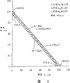
图2是本发明的实施例1中组合折射率n和组合厚度d之间的关系图;Fig. 2 is the relationship diagram between combined refractive index n and combined thickness d in
图3是本发明的实施例1中组合折射率n和组合厚度d之间的关系图;Fig. 3 is the relationship diagram between combined refractive index n and combined thickness d in
图4是本发明的实施例3中组合折射率n1和厚度d1+d2之间的关系图;Fig. 4 is a relation diagram between combined refractive index n 1 and thickness d 1 +d 2 in
图5是本发明的实施例3中组合折射率n1和厚度d1+d2之间的关系图;Fig. 5 is a diagram of the relationship between the combined refractive index n 1 and the thickness d 1 +d 2 in Example 3 of the present invention;
图6是本发明的实施例4中厚度d1和厚度d2之间的关系图;Fig. 6 is a relationship diagram between thickness d 1 and thickness d 2 in
图7是本发明的实施例5中厚度d1和厚度d2之间的关系图;Fig. 7 is a relationship diagram between thickness d 1 and thickness d 2 in Embodiment 5 of the present invention;
图8是本发明的实施例6中厚度d1和厚度d2之间的关系图;Fig. 8 is a relationship diagram between thickness d 1 and thickness d 2 in
图9是示出结合了球面象差纠正元件的光头的例子的剖面图;9 is a sectional view showing an example of an optical head incorporating a spherical aberration correcting element;
图10示出用结合了球面象差纠正元件的光头进行光盘上的记录或者从光盘中的再现;Fig. 10 shows recording on or reproduction from an optical disc with an optical head incorporating a spherical aberration correcting element;
图11示出本发明的光学信息记录/再现装置;FIG. 11 shows an optical information recording/reproducing apparatus of the present invention;
图12是常规光盘的构造的剖面图;Fig. 12 is a sectional view of the structure of a conventional optical disc;
图13是常规光盘的折射率和厚度之间的关系图;Fig. 13 is a relation diagram between the refractive index and the thickness of a conventional optical disk;
图14是常规光盘的构造的剖面图;Fig. 14 is a sectional view of the structure of a conventional optical disc;
图15是高密度光盘的构造的剖面图;Fig. 15 is a cross-sectional view of the structure of a high-density optical disc;
图16是附着层厚度和球面象差之间的关系图;Fig. 16 is a relationship diagram between the thickness of the adhesion layer and the spherical aberration;
图17(a)和17(b)是说明本发明的实施例1中方程式1和2的推导的图;以及17(a) and 17(b) are diagrams illustrating the derivation of
图18是本发明的实施例2中的光盘的构造的剖面图。Fig. 18 is a sectional view showing the structure of an optical disc in
[符号的描述][Description of symbol]
1,11,21 薄层1, 11, 21 TLC
2 涂覆层2 Coating layer
3,13,23 附着层3, 13, 23 Adhesion layer
4,14,14 保护层4, 14, 14 protective layer
5,15,25 记录层5, 15, 25 record layers
6,16,26 加固衬底6, 16, 26 Reinforced substrate
7,17,27 光盘7, 17, 27 discs
8,18,28 表面8, 18, 28 Surface
9,19,29 物镜9, 19, 29 objective lens
10 球面象差纠正元件10 Spherical aberration correction element
30 半导体激光器30 semiconductor laser
31 棱镜31 Prism
32 聚光透镜32 Condenser lens
33 反射镜33 reflector
34 球面象差纠正元件34 Spherical aberration correction element
35 物镜35 objective lens
36 物镜驱动器36 Objective lens driver
37 光盘37 CD-ROM
38 圆柱形透镜38 Cylindrical lens
39 光电检测器39 photodetector
40 光头40 bald
41 物镜41 objective lens
42 电动机42 Electric motor
43 轴43 shaft
44 磁头控制电路44 Head control circuit
45 信号处理电路45 Signal processing circuit
实现本发明的最佳方式BEST MODE FOR CARRYING OUT THE INVENTION
将参考附图来描述本发明的实施例。Embodiments of the present invention will be described with reference to the drawings.
(实施例1)(Example 1)
图1是光盘的剖面图,它是本发明的光学信息记录媒质的实施例。Fig. 1 is a sectional view of an optical disc, which is an embodiment of the optical information recording medium of the present invention.
参考图1,光盘7带有保护层4、记录层5和加固衬底6。波长为400到410nm的光通过物镜9被会聚,并且用这束光在保护层4的一侧照射记录层5,从而执行信息的记录和/或再现。Referring to FIG. 1 , an
物镜9的数值孔径很大,约为0.85。因此使用两个透镜作为物镜9。物镜9被设计以便当波长为405nm的光通过光传输平板时所产生的波阵面象差的三次球面象差成分大致为零,该光传输平板由聚碳酸脂或类似物制成并且其折射率为1.62、厚度为100μm。The numerical aperture of the objective lens 9 is very large, about 0.85. Therefore two lenses are used as objective lens 9 . The objective lens 9 is designed so that the third-order spherical aberration component of the wavefront aberration produced when light having a wavelength of 405 nm passes through a light-transmitting plate made of polycarbonate or the like and whose refraction The ratio was 1.62, and the thickness was 100 μm.
包含电介质的薄膜或反射薄膜被用作记录层5。加固衬底6防止光盘7被弯曲或折断。保护层4防止记录层5接触空气。同样,通过保护层4使光盘7的表面8与记录层5分开以防止由于表面8上的灰尘或划痕而导致的记录或再现性能的降级。A film containing a dielectric or a reflective film is used as the recording layer 5 . The reinforcing
在光盘7中,通过附着层3把薄层1和带有记录层5的加固衬底6粘结在一起,涂覆层2形成以作为用来防止划痕的表面涂层。从而,保护层4由三层形成。In the
聚碳酸脂及类似物被用于薄层1,聚丙烯树脂及类似物被用于涂层2,紫外线固化树脂及类似物被用于附着层3。在波长为405nm处的薄层1的折射率为1.62,相同波长处的涂层2的折射率为1.50,相同波长处的附着层3的折射率为1.53。即使在保护层4的设计厚度100μm中不存在误差,由于这些折射率之间的差异也会产生球面象差。因为大的数值孔径和短的波长,该球面象差的数量很大并且不可忽略。Polycarbonate and the like are used for the
在本发明的光盘中,如果波长为405nm处的薄层1、涂层2和附着层3的折射率分别为n1、n2和n3;并且这些层的厚度为d1、d2和d3(μm),则满足1.45≤n1≤1.65,1.45≤n2≤1.65,1.45≤n3≤1.65,1.45≤n≤1.65以及-3μm≤d-f(n)≤3μm。In the optical disc of the present invention, if the refractive indices of the
本发明的发明者最近介绍了组合折射率和组合厚度(即,等价于构成保护层的多层并且可替代这些层的一层的折射率和厚度)的概念,并且从而允许其中减轻球面象差的光盘的制造。The inventors of the present invention have recently introduced the concept of combined refractive index and combined thickness (i.e., the refractive index and thickness of one layer equivalent to the multiple layers that make up the protective layer and can replace these layers), and thus allow the reduction of spherical image therein. Poor disc manufacturing.
在该实施例中,组合折射率n可以通过下列方程式1来示出。In this embodiment, the combined refractive index n can be shown by
(方程式1)(Equation 1)
n=((n1d1+n2d2+...+nmdm)/(d1/n1+d2/n2+...+dm/nm))0.5 n=((n 1 d 1 +n 2 d 2 +...+n m dm)/(d 1 /n 1 +d 2 /n 2 +...+d m /n m )) 0.5
组合厚度d可以通过下列方程式2来表示。The combined thickness d can be represented by
(方程式2)(Equation 2)
d=((n1d1+n2d2+...nmdm)×(d1/n1+d2/n2+...dm/nm))0.5 d=((n 1 d 1 +n 2 d 2 +...n m d m )×(d 1 /n 1 +d 2 /n 2 +...d m /n m )) 0.5
如上所述,这些值n和d表示通过用等价于多层的一层来代替该多层而获得的组合折射率和组合厚度。通过构成保护层的多层的光的象差和通过如上推导的一个等价层的光的象差大致相等。As mentioned above, these values n and d represent the combined refractive index and combined thickness obtained by replacing the multilayer with one equivalent to the multilayer. The aberration of light passing through the multiple layers constituting the protective layer is approximately equal to the aberration of light passing through one equivalent layer as deduced above.
下面将给出这些方程式1和2的描述。Descriptions of these
下面的方程式3中示出的表达式f(n)是经过基于光线踪迹的象差计算中球面象差大致为零的离散点的三次近似曲线。f(n)的值对应于组合厚度d。The expression f(n) shown in
(方程式3)(Equation 3)
f(n)=-109.8n3+577.2n2-985.5n+648.6f(n)=-109.8n 3 +577.2n 2 -985.5n+648.6
保护层的厚度被指定在从由该曲线f(n)表示的值开始的±3μm的范围内。The thickness of the protective layer is specified within a range of ±3 μm from the value indicated by this curve f(n).
满足该条件的组合折射率n和组合厚度d在由图2中的曲线和直线围绕的区域内。虚线是曲线f(n),其上的球面象差大致为零,即,保护层4的组合厚度的设计准则。The combined refractive index n and combined thickness d satisfying this condition are within the region surrounded by the curves and straight lines in FIG. 2 . The dashed line is the curve f(n) on which the spherical aberration is approximately zero, ie the design criterion for the combined thickness of the
如果从构成保护层的多层的厚度和折射率获得的组合折射率n和组合厚度d由上述方程式1和2在该区域内(图2中实线包围的区域)确定,则可以制造其中的球面象差大致在30mλrm内的光盘。If the combined refractive index n and combined thickness d obtained from the thicknesses and refractive indices of the multilayers constituting the protective layer are determined in this region (the region surrounded by solid lines in FIG. 2 ) by the
例如,如果光盘设计为n1=1.62,d1=-50.0μm,n2=1.50,d2=5.0μm,n3=1.53以及d3=44.2μm,则可以通过方程式1和2获得组合折射率n=1.57和组合厚度d=99.2μm。通过以此方式获得的组合折射率和组合厚度而确定的点成为图2所示的曲线f(n)上的点Z,因此初始残留球面象差大致为零。在这种情况下,即使可以容忍厚度在±3μm内的变化,也可以制造其中的球面象差被限制在30mλrm的光盘。For example, if the optical disc is designed with n 1 =1.62, d 1 =-50.0 μm, n 2 =1.50, d 2 =5.0 μm, n 3 =1.53 and d 3 =44.2 μm, then the combined refraction can be obtained by
由此,根据本发明的该实施例的光盘可以通过考虑构成保护层的多层的厚度和折射率而被设计,并因此可以被制造从而限制球面象差的产生。Thus, the optical disc according to this embodiment of the present invention can be designed by considering the thickness and refractive index of the multiple layers constituting the protective layer, and thus can be manufactured so as to limit the generation of spherical aberration.
现在将进一步描述考虑构成保护层的多层的厚度和折射率的意义。The significance of considering the thickness and refractive index of the multilayers constituting the protective layer will now be further described.
也就是说,如上所述,满足方程式3的组合折射率n和组合厚度d分布在图2所示的虚线上。因此在理论上,举例来说,满足方程式3的组合折射率和组合厚度有无穷多个组合。同样,理论上来说,满足方程式1和2之间关系的每层的折射率ni和厚度di(i=1,2,3)也有无穷多个组合。That is, as described above, the combined refractive index n and combined thickness
只要从满足这些方程式的许多候选组合中选择每层的折射率ni和厚度di的适合的可实现的组合,则初始残留球面象差大致为零。从而,至于制造其总球面象差大致在30mλrm之内的光盘,则可以容忍保护层的厚度有±3μm的变化。As long as a suitable achievable combination of refractive index n i and thickness d i of each layer is selected from among many candidate combinations satisfying these equations, the initial residual spherical aberration is approximately zero. Thus, as far as manufacturing an optical disk whose total spherical aberration is within approximately 30 mλrm, a variation of ±3 µm in the thickness of the protective layer can be tolerated.
由此,根据本发明,提供了与常规光盘不一样的基于新颖的设计技术的光盘,常规光盘只从考虑保护层厚度的变化的观点并使该变化最小以便减少球面象差而被制造。Thus, according to the present invention, there is provided an optical disc based on a novel design technique unlike conventional optical discs which are manufactured only from the viewpoint of considering and minimizing variation in protective layer thickness in order to reduce spherical aberration.
也就是说,根据本发明,从满足预定方程式(本实施例中的方程式1到方程式3)的许多候选组合中选择每层的折射率ni和厚度di的组合以允许±3μm的偏差,该偏差是当前的制造技术中保护层的厚度变化的容限值。That is, according to the present invention, the combination of the refractive index n i and the thickness d i of each layer is selected from many candidate combinations satisfying the predetermined equation (
同样,包括每层的折射率ni和厚度di的各种参数的选择范围被扩展以提高设计自由度。Also, the selection range of various parameters including the refractive index ni and the thickness d i of each layer is expanded to increase the design freedom.
现在将参考图17(a)和17(b)描述上述方程式的推导过程。The derivation process of the above equation will now be described with reference to FIGS. 17(a) and 17(b).
图17(a)示出通过多层的光的折射条件,图17(b)示出通过一层的光的折射状态。为了使通过多层的象差和通过一层的象差相等,关于以角度φ入射的光线同时满足表示光通道长度的等式的条件方程式a和表示出射光位置的等式的条件方程式b。FIG. 17( a ) shows the refraction conditions of light passing through multiple layers, and FIG. 17( b ) shows the refraction state of light passing through one layer. In order to make the aberration passing through multiple layers equal to the aberration passing through one layer, conditional equation a expressing the equation of the optical channel length and conditional equation b expressing the equation of the exit light position are simultaneously satisfied with respect to the light incident at an angle φ.
(条件方程式a)(conditional equation a)
n1d1/cosθ1+n2d2/cosθ2+n3d3/cosθ3=nd/cosθn 1 d 1 /cosθ 1 +n 2 d 2 /cosθ 2 +n 3 d 3 /cosθ 3 =nd/cosθ
(条件方程式b)(conditional equation b)
d1tanθ1+d2tanθ2+d3tanθ3=dtanθd 1 tanθ 1 +d 2 tanθ 2 +d 3 tanθ 3 =dtanθ
通过根据斯涅耳定律用sinφ/sinφ1=n1,sinφ/sinφ2=n2,sinφ/sinφ3=n3略微改变这两个方程式a和b可以关于n和d同时建立和解出这两个方程式,而下列条件方程式c旁轴地建立,从而获得上述的组合折射率n和组合厚度d。These two equations a and b can be established and solved simultaneously with respect to n and d by slightly changing the two equations a and b according to Snell's law with sinφ/ sinφ1 = n1 , sinφ/ sinφ2 = n2 , sinφ/ sinφ3 = n3 equation, and the following conditional equation c is established paraxially to obtain the above-mentioned combined refractive index n and combined thickness d.
(条件方程式c)(conditional equation c)
φ=0φ=0
虽然已根据薄层1是聚碳酸脂层的情况描述了本实施例,然而薄层1也可以是聚丙烯树脂层、降冰片烯树脂层、紫外线固化树脂层等类似物。同样,虽然已描述了保护层由三层构成的情况,然而相同的描述也可以应用在保护层由两层或四层构成的情况下。Although the present embodiment has been described based on the case where the
在本发明的这个实施例中,-3μm≤d-f(n)≤3μm。然而,在用结合了球面象差纠正元件的光头执行的记录或再现的情况下,设置-10μm≤d-f(n)≤10μm是有效的。图9示出球面象差纠正元件的使用的例子。诸如日本专利揭示号为2000-131603的专利中所揭示的球面象差纠正元件10被放置在光头的光通道中。In this embodiment of the invention, -3μm≤d-f(n)≤3μm. However, in the case of recording or reproduction performed with an optical head incorporating a spherical aberration correcting element, it is effective to set -10 μm≦d-f(n)≦10 μm. Fig. 9 shows an example of use of spherical aberration correcting elements. A spherical
如果光盘厚度的变化在10μm的范围内,可以提高光盘的设计容限、改进产量和生产率、并且有助于其中很难把厚度变化限制在很小的值的表面涂覆。如果厚度根据10μm变化,产生约为100mλrm的球面象差。然而,这样的象差通过球面象差纠正元件10来纠正。例如,如果光盘上的一个光道中的厚度变化在3μm的范围内且如果表面中的厚度变化在10μm的范围内,则可以使用其中用球面象差纠正元件来进行径向厚度误差的DC纠正的方法。If the disc thickness variation is within 10 µm, it is possible to increase the design tolerance of the disc, improve yield and productivity, and facilitate surface coating where it is difficult to limit the thickness variation to a small value. If the thickness varies by 10 μm, spherical aberration of about 100 mλrm occurs. However, such aberration is corrected by the spherical
(实施例2)(Example 2)
现在将参考图18描述本发明的实施例2。
光盘7带有保护层4和4d、两个记录层5和5d以及加固衬底6。波长为400到410nm的光通过物镜9会聚,记录层5和5d在保护层4的一侧被这束光照射,从而执行信息的记录和/或再现。带有两个记录层的光盘被实现为DVD。从而信息量大致可以被翻倍。The
物镜9的数值孔径很大,约为0.85。因此用两个透镜作为物镜9。物镜9被设计以使当波长为405 nm的光通过由聚碳酸脂及类似物制成并且折射率为1.62、厚度为100μm的光传输平板时,产生波阵面象差的三次球面象差成分。诸如日本专利揭示号为2000-131603的专利中所揭示的球面象差纠正元件10被放置在光头的光通道中,以纠正由于保护层4和4d的厚度中的误差而产生的球面象差,它大约为100μm。The numerical aperture of the objective lens 9 is very large, about 0.85. Therefore, two lenses are used as objective lens 9 . The objective lens 9 is designed so that when light having a wavelength of 405 nm passes through a light-transmitting flat plate made of polycarbonate and the like and having a refractive index of 1.62 and a thickness of 100 μm, the third-order spherical aberration component of the wavefront aberration is generated . A spherical
记录层5和5d是包含电介质或反射薄膜的薄膜。加固衬底6防止光盘7被弯曲或折断。保护层4防止记录层5接触空气。同样,光盘7的表面8由保护层4与记录层5分开以防止由于表面8上的灰尘或划痕而产生的记录或再现性能的降级。The recording layers 5 and 5d are films including dielectric or reflective films. The reinforcing
与记录层5相关的保护层4由薄层1和涂覆层2构成。与记录层5d相关的保护层4d由薄层1、涂覆层2和附着层3构成。The
聚碳酸脂及类似物被用于薄层1,聚丙烯树脂及类似物被用于涂覆层2,紫外线固化树脂及类似物被用于附着层3。波长为405nm处的薄层1的折射率为1.62,相同波长处的涂覆层2的折射率为1.50,相同波长处的附着层3的折射率为1.53。Polycarbonate and the like are used for the
在本发明的光盘中,如果波长为405nm处薄层1、涂覆层2和附着层3的折射率分别为n1、n2和n3;并且这些层的厚度分别为d1、d2和d3(μm),则满足1.45≤n1≤1.65,1.45≤n2≤1.65,1.45≤n3≤1.65,1.45 ≤n≤1.65,以及f(n)-10(μm)≤d≤g(n)+10(μm)。In the optical disc of the present invention, if the refractive indices of the
关于保护层4,组合折射率n和组合厚度d可以由下列方程式4和5来表示。Regarding the
(方程式4)(Equation 4)
n=((n1d1+n2d2)/(d1/n1+d2/n2))0.5 n=((n 1 d 1 +n 2 d 2 )/(d 1 /n 1 +d 2 /n 2 )) 0.5
(方程式5)(Equation 5)
d=((n1d1+n2d2)×(d1/n1+d2/n2))0.5关于保护层4d,组合折射率n和组合厚度d可以由下列方程式6和7来表示。d=((n 1 d 1 +n 2 d 2 )×(d 1 /n 1 +d 2 /n 2 )) 0.5 Regarding the protective layer 4d, the combined refractive index n and combined thickness d can be given by the following
(方程式6)(Equation 6)
n=((n1d1+n2d2+n3d3)/(d1/n1+d2/n2+d3/n3))0.5 n=((n 1 d 1 +n 2 d 2 +n 3 d 3 )/(d 1 /n 1 +d 2 /n 2 +d 3 /n 3 )) 0.5
(方程式7)(Equation 7)
d=((n1d1+n2d2+n3d3)×(d1/n1+d2/n2+d3/n3))0.5 d=((n 1 d 1 +n 2 d 2 +n 3 d 3 )×(d 1 /n 1 +d 2 /n 2 +d 3 /n 3 )) 0.5
组合折射率n和组合厚度d是本发明特有的组合折射率和组合厚度,它们通过用等价于多层的一层来替代多层而获得。通过多层的光的象差和通过等价于多层的一层的光的象差大致相等。The combined refractive index n and combined thickness d are specific combined refractive indices and combined thicknesses of the present invention, which are obtained by replacing the multiple layers with one layer equivalent to the multiple layers. The aberration of light passing through multiple layers is approximately equal to the aberration of light passing through one layer equivalent to the multiple layers.
这些方程式4到7的推导可能与实施例1的说明中描述的推导方法相同。The derivation of these
下列方程式8和9所示的表达式f(n)和g(n)的每个都是经过离散点的三次近似曲线,当基于光线踪迹的象差计算中-15μm和15μm的组合厚度误差被球面象差纠正元件纠正时,在这些离散点处所获得的球面象差大致为零。方程式8和9是保护层4和4d的组合厚度的设计准则。Each of the expressions f(n) and g(n) shown in the following
(方程式8)(Equation 8)
f(n)=-105.8n3+551.5n2-936.9n+605.2f(n)=-105.8n 3 +551.5n 2 -936.9n+605.2
(方程式9)(Equation 9)
g(n)=-138.7n3+723.7n2-1228.7n+796.0g(n)=-138.7n 3 +723.7n 2 -1228.7n+796.0
满足这些条件中的每个的组合折射率n和组合厚度d处于由图3中的曲线和直线所围绕的区域中。每根虚线都是曲线f(n)或g(n),通过球面象差纠正元件纠正了±15μm的厚度误差而使这些曲线上的球面象差大致为零。The combined refractive index n and combined thickness d satisfying each of these conditions are in the region surrounded by the curved line and the straight line in FIG. 3 . Each dashed line is a curve f(n) or g(n) on which the spherical aberration is substantially zero by correcting the thickness error of ±15 μm by the spherical aberration correcting element.
如果在该区域(由图3中的实线围绕的区域)内确定了从构成每个保护层的多层的厚度和折射率所获得的折射率n和厚度d,则可以制造出结合了球面象差纠正元件的光盘,其球面象差大致被限制在30mλrm。If the refractive index n and the thickness d obtained from the thickness and refractive index of the multilayers constituting each protective layer are determined within this region (the region surrounded by the solid line in Fig. 3), it is possible to manufacture a combination of spherical The spherical aberration of the optical disk of the aberration correcting element is limited to approximately 30mλrm.
如果光盘上的一根光道中的厚度变化在3μm的限制范围内并且如果用球面象差纠正元件通过DC纠正来纠正径向厚度误差,则球面象差大致被限制在30mλrm。厚度中大约±20μm的纠错能力可以容易地被实现为球面象差纠正元件的纠错能力。If the thickness variation in one track on the optical disc is within the limit of 3 µm and if the radial thickness error is corrected by DC correction with a spherical aberration correcting element, the spherical aberration is limited to approximately 30mλrm. The error correction ability of about ±20 μm in thickness can be easily realized as the error correction ability of the spherical aberration correcting element.
如果第一记录层和第二记录层之间的层的组合厚度被设置为20μm或更大,则该层起到用来分开两个记录层的焦距误差信号的分离层的作用。同样也能获得减少由另一个记录层的折射造成的漫射光的数量的作用。If the combined thickness of the layers between the first recording layer and the second recording layer is set to 20 μm or more, this layer functions as a separation layer for separating the focus error signals of the two recording layers. The effect of reducing the amount of stray light caused by refraction of another recording layer can also be obtained.
由此,在本发明的实施例中,考虑构成保护层的多层的每一层的厚度和折射率以允许其中限制了球面象差的产生的光盘的制造。Thus, in an embodiment of the present invention, the thickness and refractive index of each of the multiple layers constituting the protective layer are considered to allow the manufacture of an optical disc in which the generation of spherical aberration is limited.
虽然本说明书的情况中薄层1是聚碳酸脂层,然而薄层1也可以是聚丙烯树脂层、降冰片烯树脂层、紫外线固化树脂层等类似物。同样,虽然本说明书中保护层由三层构成,然而相同的描述也可以应用在保护层由两层或四层构成的其它情况中。Although the
(实施例3)(Example 3)
现在将参考图9描述本发明的实施例3。该实施例中的光盘7与本发明的实施例1中的光盘具有相同的构造。
在本发明的光盘7中,如果在波长为405nm处薄层1、涂覆层2和附着层3的折射率分别为n1、n2a和n2b;薄层1的厚度为d1(μm);保护层4的厚度为d1+d2(μm),则满足1.45≤n1≤1.65,1.50≤n2a≤1.55,1.50≤n2b≤1.55,1.45≤n≤1.65,以及-3μm≤d1+d2-f(n1)≤3μm。In the
在该表达式中,
表达式f(n1)是用系数A、B、C和D表示的n1的三次表达式,系数A、B、C和D的每个都用d2作为参数来表示。表达式f(n1)表示了经过离散点的三次近似曲线,在基于光线踪迹的象差计算中,这些离散点处的球面象差大致为零。厚度被预先规定在离开这条曲线的3μm的范围内。The expression f(n 1 ) is a cubic expression of n 1 represented by coefficients A, B, C, and D, each of which is represented by d 2 as a parameter. The expression f(n 1 ) represents a cubic approximation curve passing through discrete points, and in the aberration calculation based on ray traces, the spherical aberration at these discrete points is approximately zero. The thickness is predetermined to be within 3 μm from this curve.
满足该条件的折射率n1和厚度d1+d2处于由图4中的曲线和直线所围绕的区域中。虚线是沿着其上的球面象差大致为零的曲线f(n1)。本发明的这个实施例的特征在于,通过考虑附着层3和涂覆层2对球面象差的影响来改变用厚度d2作为参数的曲线f(n1)。如果在该区域内确定了折射率n1和厚度d1+d2,则可以制造其中的球面象差被大致限制在30mλrm的光盘。The refractive index n 1 and the thickness d 1 +d 2 satisfying this condition are in the region surrounded by the curved line and the straight line in FIG. 4 . The dashed line is the curve f(n 1 ) along which the spherical aberration is substantially zero. This embodiment of the invention is characterized in that the curve f(n 1 ) with the thickness d 2 as parameter is modified by taking into account the influence of the
图5示出当d2的值改变时的曲线d1+d2=f(n1)。同样,画出了在基于光线踪迹的象差计算中球面象差大致为零的点。其间的误差为0.1μm或更小,并且可以认可其间的良好匹配。FIG. 5 shows the curve d 1 +d 2 =f(n 1 ) when the value of d 2 is changed. Also, the point at which spherical aberration is approximately zero in the raytrace-based aberration calculation is plotted. The error therebetween is 0.1 μm or less, and good matching therebetween can be recognized.
因此,在本发明的实施例中,考虑构成保护层的多层的每一层的厚度和折射率以允许其中限制了球面象差的产生的光盘的制造。Therefore, in an embodiment of the present invention, the thickness and refractive index of each of the multiple layers constituting the protective layer are considered to allow the manufacture of an optical disc in which the generation of spherical aberration is limited.
虽然本说明书的情况中薄层1是聚碳酸脂层,然而薄层1也可以是聚丙烯树脂层、降冰片烯树脂层、紫外线固化树脂层等类似物。同样,虽然本说明书中保护层由三层构成,然而相同的描述也可以应用在保护层由两层或四层或更多层构成的其它情况中。Although the
在本发明的这个实施例中,-3μm≤d1+d2-f(n1)≤3μm。然而,记录或再现是用结合了球面象差纠正元件的光头所执行时,设置-10μm≤d1+d2-f(n1)≤10μm是有效的。图9示出了使用球面象差纠正元件的一个例子。诸如日本专利揭示号为2000-131603的专利中所揭示的球面象差纠正元件10被放置在光头的光通道中。In this embodiment of the invention, -3 μm≦d 1 +d 2 -f(n 1 )≦3 μm. However, when recording or reproduction is performed with an optical head incorporating a spherical aberration correcting element, it is effective to set -10 µm≦ d 1 +d 2 -f(n 1 )≦10 µm. Fig. 9 shows an example of using a spherical aberration correcting element. A spherical
如果光盘厚度的变化在10μm的限制范围内,则提高了光盘设计容限、改进了产量和生产率、并且有助于其中很难把厚度变化范围限制在很小的值的表面涂覆。如果厚度变化为10μm,则产生大约100mλrm的球面象差。然而,这样的象差被球面象差纠正元件10所纠正。例如,如果光盘上的一个光道中的厚度变化在3μm的范围内且如果表面中的厚度变化在10μm的范围内,则可以使用其中用球面象差纠正元件来进行径向厚度误差的DC纠正的方法。If disc thickness variation is within the 10 μm limit, it increases disc design tolerances, improves yield and productivity, and facilitates surface coating where it is difficult to limit thickness variation to small values. If the thickness variation is 10 μm, spherical aberration of about 100 mλrm occurs. However, such aberration is corrected by the spherical
(实施例4)(Example 4)
现在将参考图9描述本发明的实施例4。本实施例的光盘7具有与本发明的实施例1中的光盘相同的构造。
在本发明的光盘7中,如果在波长为405nm处薄层1、涂覆层2和附着层3的折射率分别为n1、n2a和n2b;薄层1的厚度为d1(μm);保护层4的厚度为d1+d2(μm),则满足1.61≤n1≤1.63,1.50≤n2a≤1.55,1.50≤n2b≤1.55,以及-3μm≤d2-f(d1)≤3μm。表达式f(d1)是f(d1)=-0.986d1+98.6,它是经过离散点的近似直线,在基于光线踪迹的象差计算中这些点处的球面象差大致为零。In the
满足该条件的厚度d1和d2处于图6中的阴影区域中。如果厚度d1和d2被确定在该区域内,则可以制造其中球面象差大致被限制在30mλrm的光盘。Thicknesses d 1 and d 2 satisfying this condition are in the hatched area in FIG. 6 . If the thicknesses d1 and d2 are determined within this region, it is possible to manufacture an optical disc in which the spherical aberration is limited to approximately 30mλrm.
在聚碳酸脂及类似物被用于薄层1的情况下,本发明的这个实施例是有效的。虽然本说明书中保护层由三层构成,然而相同的描述也可以应用在保护层由两层或四层或更多层构成的其它情况中。This embodiment of the invention is effective in the case where polycarbonate and the like are used for the
在本发明的这个实施例中,-3μm≤d2-f(d1)≤3μm。然而,记录或再现是用结合了球面象差纠正元件的光头所执行时,设置-10μm≤d2-f(d1)≤10μm是有效的。In this embodiment of the invention, -3 μm≤d 2 -f(d 1 )≤3 μm. However, when recording or reproduction is performed with an optical head incorporating a spherical aberration correcting element, it is effective to set -10 µm ≤ d 2 -f(d 1 ) ≤ 10 µm.
(实施例5)(Example 5)
现在将参考图9描述本发明的实施例5。本实施例的光盘7具有与本发明的实施例1中的光盘相同的构造。Embodiment 5 of the present invention will now be described with reference to FIG. 9 . The
在本发明的光盘7中,如果在波长为405nm处薄层1、涂覆层2和附着层3的折射率分别为n1、n2a和n2b薄层1的厚度为d1(μm);保护层4的厚度为d1+d2(μm),则满足1.49≤n1≤1.51,1.50≤n2a≤1.55,1.50≤n2b≤1.55,以及-3μm≤d2-f(d1)≤3μm。表达式f(d1)是f(d1)=-1.002d1+98.6,它是经过离散点的近似直线,在基于光线踪迹的象差计算中这些点处的球面象差大致为零。In the
满足该条件的厚度d1和d2处于图7中的阴影区域中。如果在该区域内确定厚度d1和d2,则可以制造其中球面象差大致被限制在30mλrm的光盘。Thicknesses d 1 and d 2 satisfying this condition are in the hatched area in FIG. 7 . If the thicknesses d 1 and d 2 are determined in this region, an optical disc in which the spherical aberration is limited to approximately 30 mλrm can be manufactured.
在聚炳烯树脂及类似物被用于薄层1的情况下,本发明的这个实施例是有效的。虽然本说明书中保护层由三层构成,然而相同的描述也可以应用在保护层由两层或四层或更多层构成的其它情况中。In the case where polypropylene resin and the like are used for the
在本发明的这个实施例中,-3μm≤d2-f(d1)≤3μm。然而,记录或再现是用结合了球面象差纠正元件的光头所执行时,设置-10μm≤d2-f(d1)≤10μm是有效的。In this embodiment of the invention, -3 μm≤d 2 -f(d 1 )≤3 μm. However, when recording or reproduction is performed with an optical head incorporating a spherical aberration correcting element, it is effective to set -10 µm ≤ d 2 -f(d 1 ) ≤ 10 µm.
(实施例6)(Example 6)
现在将参考图9描述本发明的实施例5。本实施例的光盘7具有与本发明的实施例1中的光盘相同的构造。Embodiment 5 of the present invention will now be described with reference to FIG. 9 . The
在本发明的光盘7中,如果在波长为405nm处薄层1、涂覆层2和附着层3的折射率分别为n1、n2a和n2b;薄层1的厚度为d1(μm);保护层4的厚度为d1+d2(μm),则满足1.51≤n1≤1.54,1.50≤n2a≤1.55,1.50≤n2b≤1.55,以及-3μm≤d2-f(d1)≤3μm。In the
表达式f(d1)是f(d1)=-d1+98.6,它是经过离散点的近似直线,在基于光线踪迹的象差计算中这些点处的球面象差大致为零。The expression f(d 1 ) is f(d 1 )=-d 1 +98.6, which is an approximate straight line passing through discrete points where the spherical aberration is approximately zero in the ray trace based aberration calculation.
满足该条件的厚度d1和d2处于图8中的阴影区域中。如果厚度d1和d2被确定在该区域内,则可以制造其中球面象差大致被限制在30mλrm的光盘。Thicknesses d 1 and d 2 satisfying this condition are in the hatched area in FIG. 8 . If the thicknesses d1 and d2 are determined within this region, it is possible to manufacture an optical disc in which the spherical aberration is limited to approximately 30mλrm.
在降冰片烯树脂及类似物被用于薄层1的情况下,本发明的这个实施例是有效的。虽然本说明书中保护层由三层构成,然而相同的描述也可以应用在保护层由两层或四层或更多层构成的其它情况中。This embodiment of the present invention is effective in the case where norbornene resin and the like are used for the
在本发明的这个实施例中,-3μm≤d2-f(d1)≤3μm。然而,记录或再现是用结合了球面象差纠正元件的光头所执行时,设置-10μm≤d2-f(d1)≤10μm是有效的。In this embodiment of the invention, -3 μm≤d 2 -f(d 1 )≤3 μm. However, when recording or reproduction is performed with an optical head incorporating a spherical aberration correcting element, it is effective to set -10 µm ≤ d 2 -f(d 1 ) ≤ 10 µm.
毋庸置疑,本发明的实施例1到6中的薄层1可以是紫外线固化层。Needless to say, the
(实施例7)(Example 7)
图10示出通过使用结合了球面象差纠正元件的光头根据实施例1到6之一从光盘进行记录或再现方法的例子。FIG. 10 shows an example of a method of recording or reproducing from an optical disc according to one of
从半导体激光器30发射的并且波长为405nm的光的大约一半通过棱镜31并且被聚光透镜32照准以成为大约平行的光束。该平行光束由反射镜33进行反射,通过球面象差纠正元件34,被数值孔径为0.85的物镜35会聚,并且在本发明的光盘37的记录层上形成光点。About half of the light emitted from the
由记录层反射的光再次通过物镜35和球面象差纠正元件34,被反射镜33反射,并且由聚光透镜32聚焦。大约一半的聚焦光被棱镜31反射,通过圆柱形棱镜38并且被光电检测器39检测到。The light reflected by the recording layer passes through the objective lens 35 and the spherical aberration correcting element 34 again, is reflected by the mirror 33 , and is focused by the condenser lens 32 . About half of the focused light is reflected by prism 31 , passes through cylindrical prism 38 and is detected by photodetector 39 .
光电检测器39被安排以检测再现信号、允许物镜35通过象散的方法跟随光盘37的记录层的聚焦控制信号、以及允许物镜35通过相位差方法或推挽方法跟随光盘37上的光道的跟踪控制信号。物镜35基于这些控制信号以聚焦方向和跟踪方向被物镜驱动器36驱动。The photodetector 39 is arranged to detect the reproduction signal, the focus control signal that allows the objective lens 35 to follow the recording layer of the
举例来说,球面象差纠正元件34是诸如日本专利揭示号为2000-131603的专利中所揭示的元件。球面象差纠正元件34通过纠正由于光盘37的保护层中的厚度误差和折射率误差产生的球面象差而使形成在光盘37的记录层上的光点最佳。通过球面象差纠正元件34可以容易地实现±20μm的厚度误差的纠正。如果光盘上一条光道中的厚度变化在3μm的范围内,则球面象差纠正元件34可以通过执行径向厚度误差的DC纠正把产生的球面象差限制在30mλrm。The spherical aberration correcting element 34 is, for example, an element disclosed in Japanese Patent Laid-Open No. 2000-131603. The spherical aberration correcting element 34 optimizes the light spot formed on the recording layer of the
球面象差纠正元件34由两个透镜构成。以光轴的方向改变这两个透镜间的距离以减少物镜35上的入射光的发散和会聚的程度,从而纠正球面象差。The spherical aberration correcting element 34 is composed of two lenses. The distance between these two lenses is changed in the direction of the optical axis to reduce the degree of divergence and convergence of incident light on the objective lens 35, thereby correcting spherical aberration.
通过引用日本专利揭示号为2000-131603的专利的整体揭示使其结合于此。The entire disclosure of Japanese Patent Laid-Open No. 2000-131603 is hereby incorporated by reference.
因此,当用结合了球面象差纠正元件的光头执行在本发明的光盘上的记录或再现时,球面象差可大致被限制在30mλrm,从而实现了以前从不可能实现的信息密度的改进。Therefore, when recording or reproduction on the optical disc of the present invention is performed with an optical head incorporating a spherical aberration correcting element, the spherical aberration can be limited to approximately 30mλrm, thereby achieving an improvement in information density that has never been possible before.
根据本发明,提高了关于光盘的厚度和折射率的设计容限并且改进了产量和生产率。According to the present invention, design tolerances regarding the thickness and refractive index of optical discs are increased and yield and productivity are improved.
同样,也有助于其中很难把厚度变化限制在很小的值的表面涂覆。Also, it is helpful for surface coatings where it is difficult to limit thickness variations to small values.
此外,可以通过提供两个记录层来达到进一步提高密度的作用。In addition, the effect of further increasing the density can be achieved by providing two recording layers.
(实施例8)(Embodiment 8)
图11是示出本发明的光学信息记录/再现装置的实施例的示意图。FIG. 11 is a schematic diagram showing an embodiment of the optical information recording/reproducing apparatus of the present invention.
光盘37是根据实施例1到6之一的光盘。光盘37由电动机42转动。光头40沿着轴43在光盘37的径向移动。The
为了信息的记录或再现,从光头的半导体激光器出射的光通过物镜41被会聚到光盘37的记录层。光头40的光电检测器检测允许物镜41跟随光盘37的表面的聚焦控制信号、以及允许物镜41跟随光盘37上的信息光道的跟踪控制信号。For recording or reproduction of information, light emitted from the semiconductor laser of the optical head is condensed onto the recording layer of the
光头控制电路44根据这些控制信号对光头40执行聚焦控制和跟踪控制。The optical
信号处理电路45在记录的时候通过光头40在光盘37上记录信息,并且在再现的时候从来自光头40的光电检测器的信号中再现记录在光盘37的信息光道上的光学信息。The
本发明的记录/再现装置充分地减少了形成在光盘37的记录层上的点中的球面象差来达到信息密度的增加。The recording/reproducing apparatus of the present invention sufficiently reduces spherical aberration in spots formed on the recording layer of the
即使光盘的保护层厚度方面有大的变化或者具有两个记录层,诸如日本专利揭示号为2000-131603的专利中揭示的球面象差纠正元件仍被结合在光头40中以有效地减少球面象差,从而允许正常的信息记录和再现。Even if there is a large change in the thickness of the protective layer of the optical disc or has two recording layers, a spherical aberration correcting element such as disclosed in Japanese Patent Laid-Open No. 2000-131603 is incorporated in the
本发明的光学信息记录媒质可以相同的方式被应用在任一能进行光学信息的记录和再现的类型以及仅仅再现的类型中。The optical information recording medium of the present invention can be applied in the same manner in any type capable of recording and reproduction of optical information as well as only reproduction.
虽然本发明的实施例的描述所涉及的情况中预定波长为405nm,然而也可以使用除此之外的波长,例如,在400到410nm的范围内的波长,或者任何其它的波长。Although the description of the embodiment of the present invention refers to the case where the predetermined wavelength is 405 nm, other wavelengths may be used, for example, wavelengths in the range of 400 to 410 nm, or any other wavelengths.
同样,虽然本发明的实施例的描述所涉及的情况中配备了两个记录层,然而,通过根据记录层的数量修改配备了两个记录层的情况,也可以使上述发明被应用在以类似方法配备的两个或多个记录层的情况下。Also, although the description of the embodiment of the present invention relates to the case where two recording layers are provided, however, by modifying the case where two recording layers are provided according to the number of recording layers, the above invention can also be applied to a system similar to method equipped with two or more recording layers.
同样,虽然在已描述的实施例的情况中关于表示经过球面象差大致为零处的点的近似曲线的表达式f(n)、表达式g(n)等被用作与保护层的组合厚度相关的设计准则,然而代表近似曲线的表达式的系数、次数等等不应被限于上面所描述的情况。简而言之,经过基于光线踪迹的象差计算中球面象差大致为零的点的近似曲线或直线可以足够作为被用作设计准则的相关表达式。可以根据目的来自由地选择近似程度等等。Also, while expressions f(n), expressions g(n), etc. about approximate curves representing points passing through a point at which spherical aberration is approximately zero are used in combination with the protective layer in the case of the described embodiment The thickness-dependent design criteria, however, the coefficients, degrees, etc. of the expressions representing the approximate curves should not be limited to the cases described above. In short, an approximate curve or straight line passing through a point where spherical aberration is approximately zero in ray trace-based aberration calculation may suffice as a correlation expression used as a design criterion. The degree of approximation and the like can be freely selected according to purposes.
如上所述,提供了一种设计带有记录层和保护层的光学信息记录媒质的方法,所述保护层包括至少第一到第m层(m≥2),其中如果i是满足1≤i≤m的整数;预定波长处的保护层中的第i层的折射率为ni;并且第i层的厚度为di,则(a)大致等价于构成保护层的多层并且替代这多层的一层的组合折射率n被指定为n=((n1d1+n2d2+...+nmdm)/(d1/n1+d2/n2+...+dm/nm))0.5,(b)这一层的组合厚度d被指定为d=((n1d1+n2d2+...nmdm)×(d1/n1+d2/n2+...dm/nm))0.5,以及(c)使球面象差大致为零的表示组合折射率n和组合厚度d之间的关系的相关表达式f(n)被指定为与光学信息记录媒质的组合厚度相关的设计准则,其中根据该相关表达式f(n)来确定每一层的折射率ni和厚度di。该光学信息记录媒质设计方法具有下列的作用。As described above, there is provided a method of designing an optical information recording medium with a recording layer and a protective layer comprising at least the first to mth layers (m≥2), wherein if i satisfies 1≤i ≤ m integer; the refractive index of the i-th layer in the protective layer at a predetermined wavelength is ni ; The combined refractive index n of one layer of a multilayer is specified as n=((n 1 d 1 +n 2 d 2 +...+n m dm)/(d 1 /n 1 +d 2 /n 2 +. ..+d m /n m )) 0.5 , (b) the combined thickness d of this layer is specified as d=((n 1 d 1 +n 2 d 2 +...n m d m )×(d 1 /n 1 +d 2 /n 2 +...d m /n m )) 0.5 , and (c) a correlation representing the relationship between the combined refractive index n and the combined thickness d that makes the spherical aberration approximately zero An expression f(n) from which the refractive index n i and thickness d i of each layer are determined is specified as a design criterion related to the combined thickness of the optical information recording medium. This optical information recording medium design method has the following effects.
也就是说,根据上述的设计方法,可以容易地从满足如上所述被规定为设计准则的预定关系表达式的许多ni和di的候选组合中选择每层的折射率ni和厚度di的组合,从而把初始残留球面象差大致减少为零。因此,即使可以容忍保护层厚度有±3μm的变化,也可以把光盘中的球面象差大致限制在30mλrm。That is, according to the design method described above, the refractive index n i and thickness d of each layer can be easily selected from many candidate combinations of n i and d i satisfying the predetermined relational expression specified as the design criterion as described above i , thereby reducing the initial residual spherical aberration to roughly zero. Therefore, even if a variation of ±3 µm in the thickness of the protective layer can be tolerated, the spherical aberration in the optical disc can be roughly limited to 30 mλrm.
还有,包括每层的折射率ni和厚度di的各种参数的选择范围从而被扩展以提高设计自由度。Also, the range of selection of various parameters including the refractive index ni and thickness d i of each layer is thereby expanded to increase the degree of freedom in design.
工业应用industrial application
如上所述,本发明的优点在于进一步减少了带有由与常规技术相比的多层构成的保护层的光学信息记录媒质中的球面象差,并且从而允许正常的记录和/或再现。As described above, the present invention has the advantage of further reducing spherical aberration in an optical information recording medium with a protective layer composed of multiple layers compared with the conventional art, and thereby allowing normal recording and/or reproduction.
Claims (15)
Applications Claiming Priority (2)
| Application Number | Priority Date | Filing Date | Title |
|---|---|---|---|
| JP2000304030 | 2000-10-03 | ||
| JP2000304030 | 2000-10-03 |
Related Parent Applications (1)
| Application Number | Title | Priority Date | Filing Date |
|---|---|---|---|
| CNB018167675A Division CN1204556C (en) | 2000-10-03 | 2001-09-28 | optical information recording medium |
Publications (2)
| Publication Number | Publication Date |
|---|---|
| CN1540648A CN1540648A (en) | 2004-10-27 |
| CN1312687C true CN1312687C (en) | 2007-04-25 |
Family
ID=18785139
Family Applications (2)
| Application Number | Title | Priority Date | Filing Date |
|---|---|---|---|
| CNB2004100456241A Expired - Fee Related CN1312687C (en) | 2000-10-03 | 2001-09-28 | Optical information recording medium, optical information recording/ reproducing method, and optical information recording/reproducing device |
| CNB018167675A Expired - Fee Related CN1204556C (en) | 2000-10-03 | 2001-09-28 | optical information recording medium |
Family Applications After (1)
| Application Number | Title | Priority Date | Filing Date |
|---|---|---|---|
| CNB018167675A Expired - Fee Related CN1204556C (en) | 2000-10-03 | 2001-09-28 | optical information recording medium |
Country Status (5)
| Country | Link |
|---|---|
| US (2) | US6959447B2 (en) |
| JP (1) | JP3919661B2 (en) |
| CN (2) | CN1312687C (en) |
| AU (1) | AU2001292284A1 (en) |
| WO (1) | WO2002029800A1 (en) |
Families Citing this family (8)
| Publication number | Priority date | Publication date | Assignee | Title |
|---|---|---|---|---|
| JP3919661B2 (en) * | 2000-10-03 | 2007-05-30 | 松下電器産業株式会社 | Manufacturing method of optical information recording medium |
| AU2007200467B2 (en) * | 2002-06-05 | 2009-07-30 | Lg Electronics Inc. | High-density dual-layer optical disc |
| CN100541626C (en) * | 2002-06-05 | 2009-09-16 | Lg电子株式会社 | High-density double-layer optical disc |
| DK1516323T3 (en) * | 2002-06-14 | 2007-05-14 | Koninkl Philips Electronics Nv | Double stacked optical data storage media and use of such media |
| EP1394787A3 (en) | 2002-08-28 | 2006-11-22 | Kabushiki Kaisha Toshiba | Optical disc and optical disc apparatus |
| JP4658616B2 (en) * | 2005-01-07 | 2011-03-23 | リンテック株式会社 | Protective film for optical disc and optical disc using the same |
| EP1785088A1 (en) * | 2005-11-14 | 2007-05-16 | Congener Wellness Corp. | A system and method for the management and control of cardiovascular related diseases, such as hypertension |
| JP2012164372A (en) * | 2011-02-03 | 2012-08-30 | Sony Corp | Manufacturing method of optical information recording medium and optical information recording medium |
Citations (5)
| Publication number | Priority date | Publication date | Assignee | Title |
|---|---|---|---|---|
| US5416757A (en) * | 1991-10-16 | 1995-05-16 | International Business Machines Corporation | Optical disk drive system for use with disks having different protection layer depths |
| JPH08234099A (en) * | 1994-12-14 | 1996-09-13 | Asahi Optical Co Ltd | Objective lens |
| JPH08297850A (en) * | 1995-04-25 | 1996-11-12 | Olympus Optical Co Ltd | Information recording and reproducing device |
| US5600494A (en) * | 1994-12-14 | 1997-02-04 | Asahi Kogaku Kogyo Kabushiki Kaisha | Objective lens system of an optical disk device |
| JPH10308028A (en) * | 1997-05-02 | 1998-11-17 | Nikon Corp | Optical system for optical head |
Family Cites Families (12)
| Publication number | Priority date | Publication date | Assignee | Title |
|---|---|---|---|---|
| US5392263A (en) | 1990-01-31 | 1995-02-21 | Sony Corporation | Magneto-optical disk system with specified thickness for protective layer on the disk relative to the numerical aperture of the objective lens |
| JP3104202B2 (en) * | 1997-01-31 | 2000-10-30 | ソニー株式会社 | Optical recording medium |
| JPH10302310A (en) | 1997-04-25 | 1998-11-13 | Sony Corp | Optical recording medium and optical disk device |
| JPH11203726A (en) | 1998-01-09 | 1999-07-30 | Sony Corp | optical disk |
| JP3338660B2 (en) | 1998-01-21 | 2002-10-28 | ソニー株式会社 | optical disk |
| JP4258037B2 (en) * | 1998-06-29 | 2009-04-30 | ソニー株式会社 | Optical recording medium and optical recording / reproducing apparatus using the same |
| JP2000030299A (en) * | 1998-07-10 | 2000-01-28 | Toshiba Corp | Optical head device applicable to recording medium and information recording / reproducing device suitable for the same |
| JP2000131603A (en) | 1998-10-22 | 2000-05-12 | Sony Corp | Optical head and recording / reproducing device |
| US6440516B1 (en) * | 1999-01-20 | 2002-08-27 | Sony Corporation | Optical disc |
| US6469977B2 (en) * | 1999-12-20 | 2002-10-22 | Matsushita Electric Industrial Co., Ltd. | Optical information recording medium, method for producing the same, and method and apparatus for recording/reproducing information thereon |
| CN1201309C (en) * | 2000-06-16 | 2005-05-11 | 三菱化学株式会社 | Optical information recording medium |
| JP3919661B2 (en) * | 2000-10-03 | 2007-05-30 | 松下電器産業株式会社 | Manufacturing method of optical information recording medium |
-
2001
- 2001-09-28 JP JP2002533292A patent/JP3919661B2/en not_active Expired - Fee Related
- 2001-09-28 AU AU2001292284A patent/AU2001292284A1/en not_active Abandoned
- 2001-09-28 CN CNB2004100456241A patent/CN1312687C/en not_active Expired - Fee Related
- 2001-09-28 US US10/398,030 patent/US6959447B2/en not_active Expired - Lifetime
- 2001-09-28 CN CNB018167675A patent/CN1204556C/en not_active Expired - Fee Related
- 2001-09-28 WO PCT/JP2001/008502 patent/WO2002029800A1/en not_active Ceased
-
2004
- 2004-05-11 US US10/843,118 patent/US6862740B2/en not_active Expired - Lifetime
Patent Citations (5)
| Publication number | Priority date | Publication date | Assignee | Title |
|---|---|---|---|---|
| US5416757A (en) * | 1991-10-16 | 1995-05-16 | International Business Machines Corporation | Optical disk drive system for use with disks having different protection layer depths |
| JPH08234099A (en) * | 1994-12-14 | 1996-09-13 | Asahi Optical Co Ltd | Objective lens |
| US5600494A (en) * | 1994-12-14 | 1997-02-04 | Asahi Kogaku Kogyo Kabushiki Kaisha | Objective lens system of an optical disk device |
| JPH08297850A (en) * | 1995-04-25 | 1996-11-12 | Olympus Optical Co Ltd | Information recording and reproducing device |
| JPH10308028A (en) * | 1997-05-02 | 1998-11-17 | Nikon Corp | Optical system for optical head |
Also Published As
| Publication number | Publication date |
|---|---|
| WO2002029800A1 (en) | 2002-04-11 |
| US6959447B2 (en) | 2005-10-25 |
| CN1204556C (en) | 2005-06-01 |
| CN1540648A (en) | 2004-10-27 |
| JPWO2002029800A1 (en) | 2004-02-12 |
| US20040052196A1 (en) | 2004-03-18 |
| US20040210919A1 (en) | 2004-10-21 |
| US6862740B2 (en) | 2005-03-01 |
| CN1468430A (en) | 2004-01-14 |
| JP3919661B2 (en) | 2007-05-30 |
| AU2001292284A1 (en) | 2002-04-15 |
Similar Documents
| Publication | Publication Date | Title |
|---|---|---|
| US6353592B1 (en) | Optical recording medium and optical disk device | |
| US6246656B1 (en) | Reduced thickness of a light transmissive layer for a high density optical disc | |
| EP0762403B1 (en) | Optical disk apparatus and optical head thereof | |
| US7872959B2 (en) | Objective lens, optical element, optical pick-up apparatus and optical information recording and/or reproducing apparatus equipped therewith | |
| US6175548B1 (en) | Optical recording medium and optical recording and reproducing apparatus | |
| EP0867873A2 (en) | Optical recording medium and optical disk apparatus | |
| CN102113054A (en) | Optical recording medium | |
| US20070195684A1 (en) | High-density multi-layer recording medium and an apparatus for writing to or reading from such a recording medium | |
| JP3336829B2 (en) | Compound objective lens | |
| CN1312687C (en) | Optical information recording medium, optical information recording/ reproducing method, and optical information recording/reproducing device | |
| US7149040B2 (en) | Scanning device including an objective lens formed of two materials | |
| US7539121B2 (en) | Optical recording medium and process for producing the same | |
| US7283447B2 (en) | Optical disc and optical disc apparatus | |
| JP2004288371A (en) | Optical information recording medium, optical information recording / reproducing method, and optical information recording / reproducing device | |
| JP2005166257A (en) | Optical information recording medium | |
| JP3277140B2 (en) | Objective lens and optical pickup device | |
| JP3626035B2 (en) | Optical recording / reproducing device | |
| EP0892396B1 (en) | Hologram laser unit and two-focus type optical pickup | |
| JPH10255306A (en) | Optical pickup device | |
| US20030086354A1 (en) | Objective lens, optical pickup device, recorder and reproducer | |
| US7009744B1 (en) | Scanning device including an objective system formed of a single material | |
| KR100468970B1 (en) | Polarization phase compensator and optical disc reader/writer using the same | |
| JP4076936B2 (en) | Optical recording / reproducing device | |
| US20050232126A1 (en) | Optical data storage medium and use of such medium | |
| US20070231528A1 (en) | Optical disk, optical disk manufacturing method, and optical disk reproducing method |
Legal Events
| Date | Code | Title | Description |
|---|---|---|---|
| C06 | Publication | ||
| PB01 | Publication | ||
| C10 | Entry into substantive examination | ||
| SE01 | Entry into force of request for substantive examination | ||
| C14 | Grant of patent or utility model | ||
| GR01 | Patent grant | ||
| CF01 | Termination of patent right due to non-payment of annual fee |
Granted publication date: 20070425 Termination date: 20180928 |
|
| CF01 | Termination of patent right due to non-payment of annual fee |