CN1256002A - Optical disc device - Google Patents
Optical disc device Download PDFInfo
- Publication number
- CN1256002A CN1256002A CN99800114A CN99800114A CN1256002A CN 1256002 A CN1256002 A CN 1256002A CN 99800114 A CN99800114 A CN 99800114A CN 99800114 A CN99800114 A CN 99800114A CN 1256002 A CN1256002 A CN 1256002A
- Authority
- CN
- China
- Prior art keywords
- mentioned
- circuit
- optical disc
- signal
- level
- Prior art date
- Legal status (The legal status is an assumption and is not a legal conclusion. Google has not performed a legal analysis and makes no representation as to the accuracy of the status listed.)
- Granted
Links
Images



Classifications
-
- G—PHYSICS
- G11—INFORMATION STORAGE
- G11B—INFORMATION STORAGE BASED ON RELATIVE MOVEMENT BETWEEN RECORD CARRIER AND TRANSDUCER
- G11B7/00—Recording or reproducing by optical means, e.g. recording using a thermal beam of optical radiation by modifying optical properties or the physical structure, reproducing using an optical beam at lower power by sensing optical properties; Record carriers therefor
- G11B7/08—Disposition or mounting of heads or light sources relatively to record carriers
- G11B7/09—Disposition or mounting of heads or light sources relatively to record carriers with provision for moving the light beam or focus plane for the purpose of maintaining alignment of the light beam relative to the record carrier during transducing operation, e.g. to compensate for surface irregularities of the latter or for track following
- G11B7/0901—Disposition or mounting of heads or light sources relatively to record carriers with provision for moving the light beam or focus plane for the purpose of maintaining alignment of the light beam relative to the record carrier during transducing operation, e.g. to compensate for surface irregularities of the latter or for track following for track following only
-
- G—PHYSICS
- G11—INFORMATION STORAGE
- G11B—INFORMATION STORAGE BASED ON RELATIVE MOVEMENT BETWEEN RECORD CARRIER AND TRANSDUCER
- G11B7/00—Recording or reproducing by optical means, e.g. recording using a thermal beam of optical radiation by modifying optical properties or the physical structure, reproducing using an optical beam at lower power by sensing optical properties; Record carriers therefor
-
- G—PHYSICS
- G11—INFORMATION STORAGE
- G11B—INFORMATION STORAGE BASED ON RELATIVE MOVEMENT BETWEEN RECORD CARRIER AND TRANSDUCER
- G11B11/00—Recording on or reproducing from the same record carrier wherein for these two operations the methods are covered by different main groups of groups G11B3/00 - G11B7/00 or by different subgroups of group G11B9/00; Record carriers therefor
- G11B11/10—Recording on or reproducing from the same record carrier wherein for these two operations the methods are covered by different main groups of groups G11B3/00 - G11B7/00 or by different subgroups of group G11B9/00; Record carriers therefor using recording by magnetic means or other means for magnetisation or demagnetisation of a record carrier, e.g. light induced spin magnetisation; Demagnetisation by thermal or stress means in the presence or not of an orienting magnetic field
- G11B11/105—Recording on or reproducing from the same record carrier wherein for these two operations the methods are covered by different main groups of groups G11B3/00 - G11B7/00 or by different subgroups of group G11B9/00; Record carriers therefor using recording by magnetic means or other means for magnetisation or demagnetisation of a record carrier, e.g. light induced spin magnetisation; Demagnetisation by thermal or stress means in the presence or not of an orienting magnetic field using a beam of light or a magnetic field for recording by change of magnetisation and a beam of light for reproducing, i.e. magneto-optical, e.g. light-induced thermomagnetic recording, spin magnetisation recording, Kerr or Faraday effect reproducing
- G11B11/1055—Disposition or mounting of transducers relative to record carriers
- G11B11/10556—Disposition or mounting of transducers relative to record carriers with provision for moving or switching or masking the transducers in or out of their operative position
- G11B11/10563—Access of indexed parts
-
- G—PHYSICS
- G11—INFORMATION STORAGE
- G11B—INFORMATION STORAGE BASED ON RELATIVE MOVEMENT BETWEEN RECORD CARRIER AND TRANSDUCER
- G11B7/00—Recording or reproducing by optical means, e.g. recording using a thermal beam of optical radiation by modifying optical properties or the physical structure, reproducing using an optical beam at lower power by sensing optical properties; Record carriers therefor
- G11B7/007—Arrangement of the information on the record carrier, e.g. form of tracks, actual track shape, e.g. wobbled, or cross-section, e.g. v-shaped; Sequential information structures, e.g. sectoring or header formats within a track
- G11B7/00718—Groove and land recording, i.e. user data recorded both in the grooves and on the lands
-
- G—PHYSICS
- G11—INFORMATION STORAGE
- G11B—INFORMATION STORAGE BASED ON RELATIVE MOVEMENT BETWEEN RECORD CARRIER AND TRANSDUCER
- G11B7/00—Recording or reproducing by optical means, e.g. recording using a thermal beam of optical radiation by modifying optical properties or the physical structure, reproducing using an optical beam at lower power by sensing optical properties; Record carriers therefor
- G11B7/08—Disposition or mounting of heads or light sources relatively to record carriers
- G11B7/085—Disposition or mounting of heads or light sources relatively to record carriers with provision for moving the light beam into, or out of, its operative position or across tracks, otherwise than during the transducing operation, e.g. for adjustment or preliminary positioning or track change or selection
- G11B7/08505—Methods for track change, selection or preliminary positioning by moving the head
- G11B7/08517—Methods for track change, selection or preliminary positioning by moving the head with tracking pull-in only
-
- G—PHYSICS
- G11—INFORMATION STORAGE
- G11B—INFORMATION STORAGE BASED ON RELATIVE MOVEMENT BETWEEN RECORD CARRIER AND TRANSDUCER
- G11B7/00—Recording or reproducing by optical means, e.g. recording using a thermal beam of optical radiation by modifying optical properties or the physical structure, reproducing using an optical beam at lower power by sensing optical properties; Record carriers therefor
- G11B7/08—Disposition or mounting of heads or light sources relatively to record carriers
- G11B7/085—Disposition or mounting of heads or light sources relatively to record carriers with provision for moving the light beam into, or out of, its operative position or across tracks, otherwise than during the transducing operation, e.g. for adjustment or preliminary positioning or track change or selection
- G11B7/08505—Methods for track change, selection or preliminary positioning by moving the head
- G11B7/08541—Methods for track change, selection or preliminary positioning by moving the head involving track counting to determine position
-
- G—PHYSICS
- G11—INFORMATION STORAGE
- G11B—INFORMATION STORAGE BASED ON RELATIVE MOVEMENT BETWEEN RECORD CARRIER AND TRANSDUCER
- G11B11/00—Recording on or reproducing from the same record carrier wherein for these two operations the methods are covered by different main groups of groups G11B3/00 - G11B7/00 or by different subgroups of group G11B9/00; Record carriers therefor
- G11B11/10—Recording on or reproducing from the same record carrier wherein for these two operations the methods are covered by different main groups of groups G11B3/00 - G11B7/00 or by different subgroups of group G11B9/00; Record carriers therefor using recording by magnetic means or other means for magnetisation or demagnetisation of a record carrier, e.g. light induced spin magnetisation; Demagnetisation by thermal or stress means in the presence or not of an orienting magnetic field
- G11B11/105—Recording on or reproducing from the same record carrier wherein for these two operations the methods are covered by different main groups of groups G11B3/00 - G11B7/00 or by different subgroups of group G11B9/00; Record carriers therefor using recording by magnetic means or other means for magnetisation or demagnetisation of a record carrier, e.g. light induced spin magnetisation; Demagnetisation by thermal or stress means in the presence or not of an orienting magnetic field using a beam of light or a magnetic field for recording by change of magnetisation and a beam of light for reproducing, i.e. magneto-optical, e.g. light-induced thermomagnetic recording, spin magnetisation recording, Kerr or Faraday effect reproducing
- G11B11/10582—Record carriers characterised by the selection of the material or by the structure or form
- G11B11/10584—Record carriers characterised by the selection of the material or by the structure or form characterised by the form, e.g. comprising mechanical protection elements
-
- G—PHYSICS
- G11—INFORMATION STORAGE
- G11B—INFORMATION STORAGE BASED ON RELATIVE MOVEMENT BETWEEN RECORD CARRIER AND TRANSDUCER
- G11B7/00—Recording or reproducing by optical means, e.g. recording using a thermal beam of optical radiation by modifying optical properties or the physical structure, reproducing using an optical beam at lower power by sensing optical properties; Record carriers therefor
- G11B7/007—Arrangement of the information on the record carrier, e.g. form of tracks, actual track shape, e.g. wobbled, or cross-section, e.g. v-shaped; Sequential information structures, e.g. sectoring or header formats within a track
- G11B7/00745—Sectoring or header formats within a track
-
- G—PHYSICS
- G11—INFORMATION STORAGE
- G11B—INFORMATION STORAGE BASED ON RELATIVE MOVEMENT BETWEEN RECORD CARRIER AND TRANSDUCER
- G11B7/00—Recording or reproducing by optical means, e.g. recording using a thermal beam of optical radiation by modifying optical properties or the physical structure, reproducing using an optical beam at lower power by sensing optical properties; Record carriers therefor
- G11B7/08—Disposition or mounting of heads or light sources relatively to record carriers
- G11B7/085—Disposition or mounting of heads or light sources relatively to record carriers with provision for moving the light beam into, or out of, its operative position or across tracks, otherwise than during the transducing operation, e.g. for adjustment or preliminary positioning or track change or selection
- G11B7/08505—Methods for track change, selection or preliminary positioning by moving the head
- G11B7/08529—Methods and circuits to control the velocity of the head as it traverses the tracks
Abstract
Description
技术领域technical field
本发明涉及光盘装置,更详细点说,是涉及用于向具有特定构造的纹间·纹(land-groove)光盘记录信息或从该光盘再生信息的光盘装置。The present invention relates to an optical disc device, and more specifically, to an optical disc device for recording information on or reproducing information from a land-groove optical disc having a specific structure.
背景技术Background technique
磁光(MO)盘作为可改写、存储容量大、且可靠性高的记录媒体正在受到重视,作为计算机存储器已开始投入实际使用。此外,最近,存储容量达6.0G的磁光硬盘正在实现标准化。Magneto-optical (MO) discs are being valued as rewritable, large-capacity, and highly-reliable recording media, and have begun to be put into practical use as computer memories. In addition, recently, a magneto-optical hard disk with a storage capacity of 6.0G is being standardized.
此外,已经开发出一种磁畴放大再生技术,当从磁光盘再生信号时,加交变磁场,利用交变磁场对已从记录层向再生层转写的磁畴进行放大后再生信号。利用该技术,正提出一种可以记录或再生14G硬盘的信号的磁光盘。In addition, a magnetic domain amplification and reproduction technology has been developed. When reproducing a signal from a magneto-optical disk, an alternating magnetic field is applied, and the magnetic domain that has been transferred from the recording layer to the reproduction layer is amplified by the alternating magnetic field to reproduce the signal. Using this technology, a magneto-optical disk capable of recording or reproducing signals from a 14G hard disk is being proposed.
该磁光盘具有这样的构造,即由纹间和纹形成的记录道呈螺旋或同心圆状,纹间和纹都可以记录或再生信号,从而可以提高记录密度。This magneto-optical disk has a structure in which recording tracks formed by lands and grooves are spiral or concentric, and signals can be recorded or reproduced in both the lands and grooves, so that the recording density can be increased.
为了迅速地对这样的的磁光盘的所要的地址进行存取,必需进行道间跳跃,使光学头沿磁光盘的半径方向高速移动,使激光能跳越好几个记录道。在道间跳跃时,通过检测激光横切记录道生成的跟踪误差信号,对横切的记录道数进行计数,当激光到达所要的记录道时,再开始跟踪伺服控制。In order to quickly access a desired address of such a magneto-optical disk, it is necessary to perform inter-track jumping. The optical head is moved at high speed in the radial direction of the magneto-optical disk so that the laser beam can jump over several recording tracks. When jumping between tracks, the tracking error signal generated by the laser crossing the recording track is detected, and the number of crossing recording tracks is counted. When the laser reaches the desired recording track, the tracking servo control is started.
但是存在下面的问题,因在道间跳跃时激光以很快的速度横切多个记录道,要正确地对横切的记录道数进行计数不是容易的事。结果,尽管激光还没有达到所要的记录道,但却开始进行跟踪伺服控制了。例如,当从系统发出‘跳到第N道的纹间’的指令时,却在激光到达第N道的纹时就开始跟踪伺服控制了。这时,是在一度再开始纹的跟踪伺服控制之后进行纹间的跟踪伺服控制的,所以,必须对用来拖动光学头的线性拖动装置再次施加加速电压。结果,激光就会跳过所要的纹间。However, there is the following problem. Since the laser traverses a plurality of recording tracks at a high speed during the intertrack jump, it is not easy to accurately count the number of recording tracks traversed. As a result, although the laser light has not yet reached the desired track, tracking servo control is started. For example, when the slave system sends an instruction of 'jumping to the N-th track's land', the tracking servo control starts when the laser reaches the N-th track's groove. At this time, the tracking servo control between the lands is performed after the tracking servo control of the grooves is resumed once, so the acceleration voltage must be applied again to the linear actuator for driving the optical head. As a result, the laser skips the desired land.
发明的公开disclosure of invention
本发明的目的在于提供一种光盘装置,可以识别激光照射的记录道是纹还是纹间。An object of the present invention is to provide an optical disc device capable of identifying whether a recording track irradiated with laser light is a land or a land.
本发明的另1个目的在于提供一种光盘装置,通过识别纹和纹间,可以正确迅速地进行道间跳跃。Another object of the present invention is to provide an optical disk device capable of accurately and quickly performing track jumps by identifying lands and lands.
若按照本发明的第1方面,光盘装置具有电机、光学头、检测电路和识别电路。电机使光盘转动。光学头用激光扫描因电机而转动的光盘的记录道并检测从记录道来的反射光。检测电路根据光学头的输出信号检测纹和纹间的特定结构。识别电路根据检测电路的输出信号识别光学头扫描的是纹还是纹间。According to the first aspect of the present invention, the optical disc device has a motor, an optical head, a detection circuit, and an identification circuit. The motor turns the disc. The optical head scans the recording tracks of the optical disc rotated by the motor with laser light and detects the reflected light from the recording tracks. The detection circuit detects the specific structure of the land and the land according to the output signal of the optical head. The identification circuit identifies whether the optical head scans the groove or the space according to the output signal of the detection circuit.
上述光盘装置最好进而具有拖动装置和跟踪伺服单元。拖动装置使光学头沿光盘的半径方向移动。跟踪伺服单元使光学头中的物镜沿光盘的半径方向移动,使激光跟踪记录道。拖动装置使光学头移动并使激光跳到记录道之后,跟踪伺服单元根据识别电路的识别结果开始动作。It is preferable that the above-mentioned optical disk device further has a slider and a tracking servo unit. The dragging device moves the optical head along the radial direction of the disc. The tracking servo unit moves the objective lens in the optical head along the radial direction of the optical disc to make the laser track the recording track. After the dragging device moves the optical head and makes the laser jump to the recording track, the tracking servo unit starts to act according to the recognition result of the recognition circuit.
在上述光盘装置中,检测出纹和纹间的特定构造,由此,可以识别激光光学头扫描的是纹还是纹间。结果,可以正确迅速地进行道间跳跃。In the above-mentioned optical disc device, the specific structure of the land and the land is detected, and thus, it can be identified whether the laser optical head scans the land or the land. As a result, track jumps can be performed correctly and quickly.
附图的简单说明A brief description of the drawings
图1是表示本发明实施形态的作为磁光装置的记录再生对象的磁光盘的构造的透视图。Fig. 1 is a perspective view showing the structure of a magneto-optical disk as a recording and reproducing object of a magneto-optical device according to an embodiment of the present invention.
图2是本发明实施形态的磁光盘装置的构成的方框图。Fig. 2 is a block diagram showing the structure of a magneto-optical disk device according to an embodiment of the present invention.
图3是表示图2中的光检测器和运算电路的具体构成的图。FIG. 3 is a diagram showing a specific configuration of a photodetector and an arithmetic circuit in FIG. 2 .
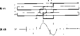
图4A是表示用激光扫描图1所示的磁光盘的纹的情况的平面图,图4B是表示当象图4A所示那样用激光扫描纹时从图3的减法电路输出的差分信号的波形图。Fig. 4A is a plan view showing the state of scanning the grooves of the magneto-optical disk shown in Fig. 1 with laser light, and Fig. 4B is a waveform diagram showing a differential signal output from the subtraction circuit of Fig. 3 when the grooves are scanned with laser light as shown in Fig. 4A .
图5A是表示用激光扫描图1所示的磁光盘的纹间的情况的平面图,图5B是表示当象图5A所示那样用激光扫描纹间时从图3的减法电路输出的差分信号的波形图。Fig. 5 A is a plan view showing the state of scanning the land of the magneto-optical disk shown in Fig. 1 with laser light, and Fig. 5 B is a diagram showing a differential signal output from the subtraction circuit of Fig. 3 when the land is scanned with laser light as shown in Fig. 5A Waveform diagram.
图6是表示图2的识别电路的具体构成的方框图。FIG. 6 is a block diagram showing a specific configuration of the identification circuit in FIG. 2 .
图7是表示图2中的运算电路和识别电路的动作的时序图。FIG. 7 is a timing chart showing operations of the calculation circuit and the recognition circuit in FIG. 2 .
图8是表示图2中的CPU的道间跳跃的动作的流程图。FIG. 8 is a flowchart showing the operation of the CPU in FIG. 2 for inter-track jumping.
图9是表示图2所示的磁光盘装置的道间跳跃的动作的图。FIG. 9 is a diagram showing an operation of a track jump in the magneto-optical disk device shown in FIG. 2 .
图10是表示在图9所示的道间跳跃的动作中从图2所示的识别电路输出的识别信号的波形图。FIG. 10 is a waveform diagram showing an identification signal output from the identification circuit shown in FIG. 2 during the track jump operation shown in FIG. 9 .
图11A是表示用激光扫描与图1所示的构造不同的磁光盘的纹或纹间的情况的平面图,图11B是表示当象图11A所示那样用激光照射纹间时从图3的减法电路输出的差分信号的波形图,图11C是表示当象图11A所示那样用激光照射纹时从图3的减法电路输出的差分信号的波形图。Fig. 11A is a plan view showing the state of scanning a land or a land of a magneto-optical disc having a structure different from that shown in Fig. 1 with laser light, and Fig. 11B is a plan view showing the subtraction from Fig. 3 when the land is irradiated with laser light as shown in Fig. 11A. Fig. 11C is a waveform diagram showing a differential signal output from the subtraction circuit of Fig. 3 when a laser beam is irradiated as shown in Fig. 11A.
图12表示用来识别图11A所示的磁光盘的纹或纹间的识别电路的具体构成的方框图。Fig. 12 is a block diagram showing a specific configuration of a recognition circuit for recognizing a land or a land in the magneto-optical disk shown in Fig. 11A.
图13是表示图12所示的识别电路的动作的波形图。FIG. 13 is a waveform diagram showing the operation of the identification circuit shown in FIG. 12 .
图14A是表示用激光扫描与图1所示的构造不同的又一种磁光盘的纹或纹间的情况的平面图,图14B是表示当象图14A所示那样用激光照射纹时从图3的减法电路输出的差分信号的波形图,图14C是表示当象图14A所示那样用激光照射纹间时从图3的减法电路输出的差分信号的波形图。Fig. 14A is a plan view showing the state of scanning the grooves or lands of yet another magneto-optical disc having a structure different from that shown in Fig. 1 with laser light, and Fig. 14B is a plan view showing when the grooves are irradiated with laser light as shown in Fig. 14A 14C is a waveform diagram showing the differential signal output from the subtraction circuit of FIG. 3 when the land is irradiated with laser light as shown in FIG. 14A.
图15是表示用来识别图14A所示的磁光盘的纹或纹间的识别电路的具体构成的方框图。Fig. 15 is a block diagram showing a specific configuration of a recognition circuit for recognizing lands or lands of the magneto-optical disk shown in Fig. 14A.
图16是表示图15所示的识别电路的动作的波形图。FIG. 16 is a waveform diagram showing the operation of the identification circuit shown in FIG. 15 .
图17是表示在纹的两侧面形成精确时标的磁光盘的平面图。Fig. 17 is a plan view showing a magneto-optical disk in which precise time marks are formed on both sides of grooves.
图18是表示在纹的一个侧面形成精确时标的磁光盘的平面图。Fig. 18 is a plan view showing a magneto-optical disk in which a precise time mark is formed on one side of a groove.
图19是表示用来识别图17和图18所示那样的磁光盘的纹和纹间的光检测器和运算电路的构成的图。FIG. 19 is a diagram showing the configuration of a photodetector and an arithmetic circuit for distinguishing lands and lands of a magneto-optical disk as shown in FIGS. 17 and 18. FIG.
实施发明的最佳形态The best form for carrying out the invention
下面,参照附图详细说明本发明的实施形态。再有,对图中同一或相当的部分附加相同的符号,不重复其说明。Hereinafter, embodiments of the present invention will be described in detail with reference to the drawings. In addition, the same code|symbol is attached|subjected to the same or equivalent part in a drawing, and the description is not repeated.
第1实施形态The first embodiment
在说明本发明的实施形态的磁光盘装置之前,先说明作为记录再生对象的磁光盘的构造。Before describing the magneto-optical disk device according to the embodiment of the present invention, the structure of the magneto-optical disk to be recorded and reproduced will be described.
如图1所示,在磁光盘1上形成螺旋状或同心圆状的纹3,结果,在相邻纹3和3之间形成纹间2。在纹间·纹式磁光盘1中,在纹和纹间都形成用于光磁记录的磁性膜。因此,纹3和纹间2便形成磁光盘1的记录道。As shown in FIG. 1, spiral or
这里,纹3不是连续形成而是以一定的间隔断断续续形成。即,在纹3上每隔一定间隔形成长度较短的纹间5。为了使这样的纹间5与通常的纹间2相区别,下面称其为‘不连续纹间5’。此外,纹间2也不是连续形成而是以一定的间隔断断续续形成。即,在纹间2上每隔一定间隔形成长度较短的纹4。为了使这样的纹4与通常的纹3相区别,下面称其为‘不连续纹4’。Here, the
纹间2和纹3的宽度大致相等,大约是0.6μm。纹3的深度大约是激光波长的1/6~1/8。不连续纹4和不连续纹间5大约每隔100μm形成,记录道方向(记录道的接线方向)10的长度与激光光斑的直径大致相同,约1μm。信号不是记录在不连续纹4和不连续纹间5上,而是记录在通常的纹3和纹间2上。The widths of the
当激光照射到上述具有特定构造的纹间2或纹3上时,反射光的强度因不连续纹4和不连续纹间5的影响而周期地变化。因此,在该磁光盘1中,通过检测这样的强度周期变化的反射光来生成同步信号,根据该同步信号进行信号的记录或再生。When laser light is irradiated on the above-mentioned
其次,说明用于对上述磁光盘1进行记录或再生的光盘装置的构成。Next, the configuration of an optical disc device for recording or reproducing the above-mentioned magneto-
本发明第1实施形态的光盘装置包括:使磁光盘1以规定的转速转动的主轴电机15;用激光扫描由主轴电机15转动的磁光盘1的记录道(2,3)并检测从磁光盘1来的反射光的光学头11;根据光学头11的输出信号生成再生信号RF、差分信号DF(后面详述)、聚焦误差信号FE和跟踪误差信号TE的运算电路12;将这些RF、DF、FE、TE信号放大的再生信号放大电路13;根据这些已放大的信号FE、TE对主轴电机15和光学头11进行伺服控制的伺服电路14;识别光学头11根据再生信号放大电路13来的已放大的差分信号所扫描的是纹间2还是纹3并生成表示该识别结果的识别信号LG的识别电路16;根据识别信号LG控制伺服电路14、时序设定电路19和线性拖动装置20的CPU(中央运算处理装置)18;解调再生信号放大电路13来的再生信号RF并输出再生数据的解调器17;生成用来与按规定的调制方式调制了的记录数据对应驱动磁头驱动电路23的时序脉冲和用来驱动激光驱动电路25的时序脉冲的时序设定电路19;根据时序设定电路19来的时序脉冲驱动磁头24的磁头驱动电路23;根据时序设定电路19来的时序脉冲驱动光学头11中半导体激光器110的激光驱动电路25;在信号记录时对磁光盘1施加磁场的磁头24;和使光学头11沿磁光盘1的跟踪方向(半径方向)移动的线性拖动装置20(参照图2)。The optical disk device of the first embodiment of the present invention includes: a spindle motor 15 that rotates the magneto-
光学头11包括:生成激光的半导体激光器110;使半导体激光器110来的激光平行的平行光管透镜111;使半导体激光器110来的激光笔直穿过而使磁光盘1来的反射光以大致90度角度反射的激光束分光器112;使半导体激光器110来的激光在磁光盘1上聚焦的物镜113;将经磁光盘1反射进而经激光束分光器112反射的激光分成3束激光(P偏振光、S偏振光、P偏振光和S偏振光的混合光)的沃拉斯顿棱镜117;使沃拉斯顿棱镜117来的3束激光聚光的聚光透镜114;检测该已聚光的反射光的光检测器115;根据伺服电路14来的控制信号使物镜113沿跟踪方向移动以便激光始终扫描磁光盘的记录道(2,3)的跟踪拖动装置116。这里,伺服电路14和跟踪拖动装置116构成进行跟踪伺服控制的跟踪伺服单元。The optical head 11 includes: a semiconductor laser 110 that generates laser light; a collimator lens 111 that makes the laser light from the semiconductor laser 110 parallel; The laser beam splitter 112 of angle reflection; The laser beam that semiconductor laser 110 comes is focused on the
光检测器115如图3所示那样分成2个传感器61和62。传感器61和62在跟踪方向10上并排配置。此外,运算电路12包括减法电路120,计算传感器61和62的输出信号的差并生成差分信号DF。传感器61的输出加给减法电路120的反相输入端子(-),传感器62的输出加给的同相输入端子(+)。因此,该减法电路120可以根据光学头11来的输出信号检测出象不连续纹4和不连续纹间5那样的的特定构造。下面对此进行具体说明。The
如图4A所示那样,当扫描纹3的激光LB到达不连续纹间5时,因最初从前面传感器62来的输出电平增大故如图4B所示那样差分信号DF的电平增大。而且,当激光LB的中心到达不连续纹间5的前缘时差分信号DF的电平最大。其后,因后面传感器61来的输出电平也增大,故差分信号DF的电平降低,当激光LB的中心到达不连续纹间5的后缘时差分信号DF的电平最小。接着,当激光LB超过不连续纹间5时,差分信号DF回到0电平。如上所述,当激光LB扫描纹3时,可以得到在最大之后变成最小的差分信号DF。As shown in FIG. 4A, when the laser beam LB scanning the
相反,当象图5A所示那样的扫描纹间2的激光LB通过不连续纹4时,可以得到在最小之后变成最大的差分信号DF。On the contrary, when the laser light LB scanning the
其次,对识别激光LB根据上述那样的差分信号所扫描的是纹间2还是纹3的识别电路的构成和动作进行说明。Next, the configuration and operation of a discrimination circuit for discriminating whether the laser beam LB scans the
识别电路16包括:将差分信号DF的电平与基准电平RH进行比较的比较器160;将差分信号与比基准电平RH还低的基准电平RL进行比较的比较器161;与比较器160的输出信号CP1同步生成规定幅度的触发脉冲信号SHOT的单触发电路162;与比较器161的输出信号CP1同步生成锁存单触发电路162的触发脉冲信号SHOT并生成识别信号LG的D(延迟)锁存电路163(参照图6)。The
首先,在激光LB扫描纹3的情况下,如图7所示那样,当差分信号DF的电平超过基准电平RH时,比较器160的输出信号CP成为H(逻辑高)电平。此后,当差分信号DF的电平低于基准电平RH时,输出信号CP1返回L(逻辑低)电平。由单触发电路162生成的触发脉冲信号SHOT响应输出信号CP1的上升沿而成为H电平。该触发脉冲信号SHOT的宽度T1设定成与激光LB通过不连续纹间5时生成的差分信号DF的周期T1相等。接着,当差分信号DF的电平低于基准电平RL时,比较器161的输出信号CP2变成L电平。此后,当差分信号DF的电平超过基准电平RL时,输出信号CP2返回H电平。因该输出信号CP2作为时钟信号供给锁存电路163,故在输出信号CP2的上升沿触发脉冲信号SHOT的逻辑电平被锁存在锁存电路163中。这里,因从输出信号CP1上升沿到输出信号CP2的上升沿的时间T2一定比触发脉冲信号SHOT的脉冲宽度T1短,故触发脉冲信号SHOT在输出信号CP2的上升沿时维持H电平。因此,当输出信号CP2上升时,触发脉冲信号SHOT的H电平被锁存在锁存电路163中。结果,从锁存电路163输出的识别信号LG直到激光LB到达纹2时为止一直维持H电平。First, when the laser beam LB scans the
另一方面,当激光LB扫描纹2时,差分信号DF的电平与上述纹间的情况相反,首先低于基准电平RL。这时,比较器161的输出信号CP2成为L电平。此后,当差分信号DF的电平超过基准电平RL时,输出信号CP2返回H电平。接着,当差分信号DF的电平超过基准电平RH时,比较器160的输出信号CP1变成H电平。此后,当差分信号DF的电平低于基准电平RH时,输出信号CP1返回L电平。与该输出信号CP1的上升沿同步生成规定宽度T1的触发脉冲信号。因在输出信号CP2的上升沿还没有生成触发脉冲信号,故输出信号CP2上升沿时的L电平的信号被锁存在锁存电路163中。因此,从锁存电路163输出的识别信号LG从H电平变成L电平。该识别信号LG直到激光LB到达纹3时为止一直维持L电平。如上所述,当激光LB扫描纹间2时,识别信号LG为L电平。On the other hand, when the laser beam LB scans the
若按照上述识别电路16,根据差分信号DF生成表示纹或纹间的识别信号LG。即,在激光LB扫描纹间2时识别信号为L电平,扫描纹3时为H电平。According to the
下面,说明象上面那样构成的磁光盘装置道间跳跃时的动作。Next, the operation of the magneto-optical disk device configured as above at the time of track jumping will be described.
首先,将磁光盘1装在主轴电机15上,使其以规定的转速旋转。这时,光学头11的激光扫描磁光盘1上的某一条记录道。First, the magneto-
当使激光从当前记录道跳到相距N个记录道的纹时,如图8所示那样,首先,在步骤S1中,CPU18关掉伺服电路14中的跟踪伺服,使记录道计数器(未图示)复位。When the laser beam is jumped from the current track to the groove of N tracks apart, as shown in FIG. shown) to reset.
接着,在步骤S2中,CPU18对线性拖动装置20施加规定的加速电压。由此,光学头11如图9所示那样沿磁光盘1的跟踪方向(半径方向)移动。这时,因磁光盘1以规定的转速旋转,故激光一边交替横切纹3和纹间2一边扫描纹3和纹间2。因此,当激光横切并扫描纹3时,生成象图4B所示那样的多个连续的差分信号DF。另一方面,当激光横切并扫描纹间2时,生成象图5B所示那样的多个连续的差分信号DF。结果,如图10所示,在激光扫描纹3期间,识别电路16输出的识别信号LG为H电平,另一方面,在激光扫描纹间2期间,为L电平。Next, in step S2 , the CPU 18 applies a predetermined acceleration voltage to the linear actuator 20 . As a result, the optical head 11 moves in the tracking direction (radial direction) of the magneto-
接着,在步骤3中,判定记录道计数器的值是否大于N/2。若记录道计数器的值未达到N/2,则继续施加加速电压。若记录道计数器的值大于N/2,则在步骤4中CPU18对线性拖动装置20不施加加速电压而施加减速电压。总之,当激光只跳过N个记录道时,在激光到达中间点之前使光学头11加速,在激光超过中间点之后使光学头11减速。这里,记录道计数器通过检测跟踪误差信号TE来对激光横切的记录道进行计数。Next, in
接着,在步骤5中,判定记录道计数器的值是否大于N。若记录道计数器的值未达到N,则继续施加减速电压。若记录道计数器的值大于N,则在步骤6中判定激光扫描的记录道是不是所要的纹3。更具体一点说,CPU18根据从识别电路16来的识别信号LG进行该判定。若激光扫描的记录道不是所要的纹3,即,若是纹间2则继续该判定。这里,若记录道计数器能正确地对记录道进行计数,当然激光就会扫描所要的纹3,但是,因激光以很高的速度横切多个记录道,故记录道计数器不一定能够对横切的所有记录道进行准确的计数。结果,有时,跳跃后激光扫描的记录道不是需要的纹间2。但是,扫描纹间2的激光不久也会扫描纹3。结果,识别信号LG变成H电平,与此对应,CPU18在步骤S7中使伺服电路14中的跟踪伺服打开。结果,对该所要的纹开始进行跟踪伺服控制。Next, in
若按照上述该实施形态,通过检测为了记录或再生而形成的不连续纹4或不连续纹间5,能够判定激光正在扫描的记录道是不是纹。此外,因识别跳跃后激光扫描的记录道是纹还是纹间,当激光到达所要的纹或纹间时才开始跟踪伺服控制,故能够使激光可靠地跳到所要的记录道上。According to the above-mentioned embodiment, by detecting the
再有,上述那样的道间跳跃动作不光在信号记录时能够进行,在信号再生时也能够进行。It should be noted that the above-mentioned track jump operation can be performed not only during signal recording but also during signal reproduction.
第2实施形态The second embodiment
在图1所示的磁光盘1中,记录或再生同步用的有凹凸的构造(不连续纹4或不连续纹间5)是在纹3和纹间2两方面形成的,但也可以在其中任何一方形成。In the magneto-
例如,也可以如图11A所示那样,不连续纹4只在纹间2上形成,图1所示那样的不连续纹间5不在纹3上形成。这样的不连续纹4也如图3所示那样能够通过光检测器115和减法电路120检测出来。For example, as shown in FIG. 11A ,
如图11A所示,当激光LB扫描纹间2且激光LB的前方到达不连续纹4时,从光检测器115的前方的传感器62输出的电平减小,结果,从减法电路120输出的差分信号DF的电平象图11B所示那样减小。当激光LB的中心正好到达不连续纹4的前缘时,差分信号DF的电平最小。然后,当激光LB的中心正好到达不连续纹4的后缘时,差分信号DF的电平最大。而且,当激光LB超过不连续纹4时,差分信号DF的电平再回到0。As shown in FIG. 11A, when the laser beam LB scans the
另一方面,当激光LB扫描纹3且通过相邻的纹间2的不连续纹4之间的区域时,能得到图11C所示的差分信号DF。因激光LB的直径比纹3的宽度大,故当激光LB位于不连续纹4的前缘或后缘的附近时,在前面传感器62和后面传感器61之间,产生输出电平的差。但是,该输出电平的差比激光LB扫描纹间2时小,所以,激光LB扫描纹3时得到的图11C所示的差分信号DF的振幅比激光LB扫描纹间2时得到的图11B所示的差分信号DF的振幅小。若检测该振幅之间的差,就能够识别激光LB扫描的记录道是纹3还是纹间2。On the other hand, when the laser beam LB scans the
图12表示用来根据图11B和图11C所示的差分信号DF识别纹或纹间的识别电路16的构成的方框图。该识别电路16包括使差分信号DF的极性反相的反相电路164、使反相电路164来的反相差分信号DFI的电平与基准电平RH进行比较的比较器160和与比较器160的输出信号CP1同步生成规定宽度的触发脉冲信号并将其作为识别信号LG输出的单触发电路162。FIG. 12 is a block diagram showing the configuration of the
当激光LB扫描纹间2时,如图13所示那样,得到开始最小后来最大的差分信号DF。该差分信号DF经反相电路164反相,得到开始最大后来最小的反相差分信号DFI。当反相差分信号DFI的电平超过基准电平RH时,比较器160的输出信号CP1成为H电平,接着,当反相差分信号DFI的电平低于基准电平RH时,输出信号CP1再返回L电平。得到与这样的输出信号CP1的上升沿同步、具有规定的宽度T3的差分信号,将该信号作为识别信号输出。该宽度T3最好设定成比差分信号DF的出现周期长,使在激光LB扫描纹间2的期间识别信号LG能维持H电平。When the laser light LB scans the
另一方面,当激光LB扫描纹3时,得到振幅小的差分信号DF。因此,该差分信号DF的电平绝对超不过基准电平RH。即,基准电平RH设定在扫描纹间时得到的差分信号的最大电平和扫描纹时得到的差分信号的最大电平之间。因此,当激光LB扫描纹3时,比较器160的输出信号CP1决不会变成H电平而是维持L电平。因此,单触发电路162不产生触发脉冲信号,结果,识别信号LG维持L电平。On the other hand, when the laser beam LB scans the
如上所述,图12所示的识别电路16在激光LB扫描纹间2时能够生成H电平的识别信号LG,在激光LB扫描纹3时能够生成L电平的识别信号LG。结果,能够识别激光束LB扫描的记录道是纹还是纹间。As described above, the
再有,图12所示的识别电路16具有反相电路164,但若将应加在比较器160的反相端子上的基准电平设定在扫描纹间时得到的差分信号的最小电平和扫描纹时得到的差分信号的最小电平之间,也可以不设置这样的反相电路164。或者,若将图3所示的前面传感器62的输出加给减法电路的反相端(-)且将后面传感器61的输出加给同相端(+),同样也可以不设置这样的反相电路164。或者,若通过检测在差分信号DF的最小电平之后出现的最大电平来生成识别信号LG,也可以不设置这样的反相电路。Furthermore, the
第3实施形态The third embodiment
如图14A所示那样,不连续纹间5在纹3上形成,但也可以不在纹间2上形成象图1所示那样的不连续纹4。As shown in FIG. 14A, the
在这样的磁光盘1中,当激光LB扫描纹3并通过不连续纹间5时,能得到图14B所示那样的振幅大的差分信号DF。另一方面,当激光LB扫描纹间2并通过相邻纹3的不连续纹间5之间的区域时,能得到图14C所示那样的振幅小的差分信号DF。In such a magneto-
图15是表示用来根据图14B和图14C所示的差分信号DF识别激光LB扫描的是纹还是纹间的识别电路的构成的方框图。FIG. 15 is a block diagram showing the configuration of a discrimination circuit for discriminating whether laser light LB scans a land or a land based on the differential signal DF shown in FIGS. 14B and 14C.
该识别电路16包括使差分信号DF的电平与基准电平RH进行比较的比较器160和与比较器160的输出信号CP1同步生成规定宽度的触发脉冲信号并将其作为识别信号LG输出的单触发电路162。The
如图16所示那样,首先,当激光LB扫描纹3并通过不连续纹间5时,能得到振幅大的差分信号DF。因该差分信号DF的最大电平超过基准电平RH,故比较器160的输出信号CP1变成H电平。与该输出信号CP1的上升沿同步生成具有规定宽度的触发脉冲信号,将该信号作为识别信号LG输出。该宽度T4也与上述宽度T3一样,最好设定得比差分信号DF的出现周期长。As shown in FIG. 16, first, when the laser beam LB scans the
另一方面,当激光LB扫描纹间2并通过相邻纹3的不连续纹间5之间的区域时,能得到振幅小的差分信号DF。因该差分信号DF的最大电平不超过基准电平RH,故比较器160的输出信号CP1不会变成H电平。因此,不生成触发脉冲信号,识别信号LG维持L电平。On the other hand, when the laser light LB scans the
如上所述,激光LB扫描纹3时识别信号LG为H电平,激光LB扫描纹间2时识别信号LG为L电平,所以,能够识别激光LB扫描的记录道是纹还是纹间。As described above, the identification signal LG is at the H level when the laser LB scans the
第4实施形态The fourth embodiment
在图l、图11和图14所示的磁光盘中,形成不连续纹4或不连续纹间5,但也可以在纹和纹间的至少一方形成某种具有凹凸的构造。In the magneto-optical discs shown in FIGS. 1, 11, and 14,
例如,如图17所示,为了信号的同步记录或同步再生,也可以是形成有精确时标的磁光盘。在图17所示的磁光盘中,在纹3的两侧壁,相对纹3的中心线呈线对称形成起伏,由此形成精确时标6和7。此外,在图18所示的磁光盘中,只在纹3的一个侧壁形成起伏,由此形成精确时标6。纹3的另一侧壁则是平坦的。For example, as shown in FIG. 17, a magneto-optical disc with a precise time mark may be used for synchronous recording or synchronous reproduction of signals. In the magneto-optical disk shown in FIG. 17, undulations are formed line-symmetrically with respect to the center line of the
图19示出用于检测图17和图18所示的精确时标6、7的光检测器115和加法电路121的构成。这里,设置加法电路121代替减法电路120。光检测器115前面的传感器62的输出加给加法电路12l的一个输入端,后面的传感器6l的输出加给加法电路12l的另一个输入端。FIG. 19 shows the composition of a
当激光扫描纹3并通过精确时标6、7时,能得到和图4B所示的差分信号DF同极性的和信号SM。另一方面,当激光扫描纹间2并通过精确时标6、7时,能得到和图5B所示的差分信号DF同极性的和信号SM。因此,若使用例如图6所示的识别电路16,就能够根据这样的和信号SM识别激光扫描的记录道是纹还是纹间。When the laser scans the
再有,图17所示的精确时标6、7是通过使纹3的两侧壁起伏、使其宽度变化而形成的,但也可以使纹的宽度始终保持一定,使该两侧壁以相同的位相起伏。Furthermore, the
此外,在上述实施形态中,说明了磁光盘,但不限于此,只要是纹间·纹(land-and-groove)方式的记录媒体,都可以适用本发明。In addition, in the above-mentioned embodiments, a magneto-optical disk has been described, but it is not limited thereto, and the present invention can be applied to any recording medium of a land-and-groove system.
还应该指出,这次公开的实施形态所有各点都是例示性的东西,没有限制。本发明的范围不是上述的说明而是由权利要求的范围表示,这意味着与权利要求的范围均等的和在范围内的所有变更也包含在权利要求的范围之内。It should also be noted that the embodiments disclosed this time are illustrative in every point and not restrictive. The scope of the present invention is shown not by the above-described description but by the claims, and it means that all modifications within the range equivalent to the claims are also included in the claims.
工业上利用的可能性Possibility of industrial use
本发明是用于纹间·纹(land-and-groove)方式的记录媒体的光盘装置,特别可以利用作为可进行道间跳跃的磁光盘装置。The present invention is an optical disc device used for a recording medium of a land-and-groove system, and is particularly applicable as a magneto-optical disc device capable of track jumping.
Claims (11)
Applications Claiming Priority (2)
| Application Number | Priority Date | Filing Date | Title |
|---|---|---|---|
| JP2580098 | 1998-02-06 | ||
| JP25800/1998 | 1998-02-06 |
Publications (2)
| Publication Number | Publication Date |
|---|---|
| CN1256002A true CN1256002A (en) | 2000-06-07 |
| CN1127721C CN1127721C (en) | 2003-11-12 |
Family
ID=12175938
Family Applications (1)
| Application Number | Title | Priority Date | Filing Date |
|---|---|---|---|
| CN99800114A Expired - Fee Related CN1127721C (en) | 1998-02-06 | 1999-02-03 | Optical disc device |
Country Status (5)
| Country | Link |
|---|---|
| EP (1) | EP0974958A4 (en) |
| KR (1) | KR100342955B1 (en) |
| CN (1) | CN1127721C (en) |
| AU (1) | AU2185999A (en) |
| WO (1) | WO1999040576A1 (en) |
Families Citing this family (4)
| Publication number | Priority date | Publication date | Assignee | Title |
|---|---|---|---|---|
| JP2002117535A (en) * | 2000-10-05 | 2002-04-19 | Sanyo Electric Co Ltd | Disk device |
| JP2002117537A (en) * | 2000-10-10 | 2002-04-19 | Sanyo Electric Co Ltd | Disk device |
| CN1207708C (en) | 2000-10-23 | 2005-06-22 | 三洋电机株式会社 | Optical disk apparatus capable of generating clock accurately |
| JPWO2002035528A1 (en) * | 2000-10-26 | 2004-03-04 | 三洋電機株式会社 | Optical disc apparatus capable of adjusting phase of reproduction clock and phase adjustment method |
Family Cites Families (7)
| Publication number | Priority date | Publication date | Assignee | Title |
|---|---|---|---|---|
| US5452284A (en) * | 1992-09-14 | 1995-09-19 | Matsushita Electric Industrial Co., Ltd. | Optical recording/reproducing medium and apparatus using land and groove encoded information signals and identification signals including position information |
| US5872767A (en) * | 1995-02-17 | 1999-02-16 | Matsushita Electric Industrial Co., Ltd. | Optical disk and an optical disk recording/reproduction device having address blocks located on boundary lines between adjoining tracks |
| US5896365A (en) * | 1995-04-28 | 1999-04-20 | Canon Kabushiki Kaisha | Optical information recording medium capable of recording in lands and grooves without a track-jumping operation; optical information recording/reproducing apparatus using, and master disk exposure apparatus for producing the same |
| JP3092510B2 (en) * | 1996-04-15 | 2000-09-25 | 三菱電機株式会社 | Optical disk medium and optical disk device |
| JPH09293244A (en) * | 1996-04-25 | 1997-11-11 | Mitsubishi Electric Corp | Optical disc and optical disc device |
| JPH1011760A (en) * | 1996-06-24 | 1998-01-16 | Mitsubishi Electric Corp | Optical disc and optical disc tracking method |
| JPH1125461A (en) * | 1997-07-01 | 1999-01-29 | Seiji Yonezawa | Optical disk and recording / reproducing apparatus for the same |
-
1999
- 1999-02-03 KR KR1019997008526A patent/KR100342955B1/en not_active Expired - Fee Related
- 1999-02-03 AU AU21859/99A patent/AU2185999A/en not_active Abandoned
- 1999-02-03 WO PCT/JP1999/000450 patent/WO1999040576A1/en not_active Ceased
- 1999-02-03 CN CN99800114A patent/CN1127721C/en not_active Expired - Fee Related
- 1999-02-03 EP EP99901934A patent/EP0974958A4/en not_active Withdrawn
Also Published As
| Publication number | Publication date |
|---|---|
| KR20000076422A (en) | 2000-12-26 |
| WO1999040576A1 (en) | 1999-08-12 |
| EP0974958A4 (en) | 2007-01-10 |
| AU2185999A (en) | 1999-08-23 |
| CN1127721C (en) | 2003-11-12 |
| EP0974958A1 (en) | 2000-01-26 |
| KR100342955B1 (en) | 2002-07-05 |
Similar Documents
| Publication | Publication Date | Title |
|---|---|---|
| EP0522499B1 (en) | Optical medium reproducing system with accurate track position detection | |
| JP2633417B2 (en) | Optical recording medium drive | |
| JP3890709B2 (en) | Optical recording medium driving apparatus and optical recording medium discrimination method | |
| CN1127721C (en) | Optical disc device | |
| KR100379399B1 (en) | Method and apparatus for detecting header area of optical record medium and method for recording/playing using the same | |
| KR101002538B1 (en) | Optical disc drive, method of obtaining optical focus, computer readable storage medium storing processors and programs | |
| CN1110039C (en) | Method for tracking optical disc of shallow/deep groove type and apparatus adopting the same | |
| JP2000076718A (en) | Magneto-optical recording medium | |
| US20100002554A1 (en) | Optical disk device and optical disk type determination method | |
| JP2000030353A (en) | Optical recording medium determination method and optical disk device | |
| JP2000251383A5 (en) | Disk drive device, recording layer identification method | |
| JP2004192784A (en) | Optical disk drive | |
| JP2728620B2 (en) | Optical recording / reproducing device | |
| JP3854075B2 (en) | Optical disc drive device and optical disc device | |
| JP2004046977A (en) | Optical disk discriminator | |
| KR100698105B1 (en) | Method and apparatus for determining land / groove track of optical record carrier | |
| JP2005038514A (en) | Optical discriminating device | |
| JP2003030863A (en) | Optical disc reproducing apparatus and disc discriminating method thereof | |
| KR100662265B1 (en) | Method for detecting non-recording area of optical record carrier, recording / reproducing method using same, and apparatus therefor | |
| JP2008097739A (en) | Disk player and disk discriminating method | |
| JP2005346809A (en) | Optical disk recording and reproducing device | |
| JP2006302379A (en) | Optical disk apparatus, and focus control method of optical disk apparatus | |
| JP2004272989A (en) | Optical disk drive | |
| JP2006277846A (en) | Disk discrimination method and disk-discriminating apparatus | |
| JP2003338046A (en) | Optical disk drive |
Legal Events
| Date | Code | Title | Description |
|---|---|---|---|
| C06 | Publication | ||
| PB01 | Publication | ||
| C10 | Entry into substantive examination | ||
| SE01 | Entry into force of request for substantive examination | ||
| C14 | Grant of patent or utility model | ||
| GR01 | Patent grant | ||
| C19 | Lapse of patent right due to non-payment of the annual fee | ||
| CF01 | Termination of patent right due to non-payment of annual fee |