CN1253065C - Working equipment with front rotary working unit - Google Patents
Working equipment with front rotary working unit Download PDFInfo
- Publication number
- CN1253065C CN1253065C CNB03100637XA CN03100637A CN1253065C CN 1253065 C CN1253065 C CN 1253065C CN B03100637X A CNB03100637X A CN B03100637XA CN 03100637 A CN03100637 A CN 03100637A CN 1253065 C CN1253065 C CN 1253065C
- Authority
- CN
- China
- Prior art keywords
- engine
- working
- equipment
- rotating
- shaft
- Prior art date
- Legal status (The legal status is an assumption and is not a legal conclusion. Google has not performed a legal analysis and makes no representation as to the accuracy of the status listed.)
- Expired - Fee Related
Links
Images


Classifications
-
- A—HUMAN NECESSITIES
- A01—AGRICULTURE; FORESTRY; ANIMAL HUSBANDRY; HUNTING; TRAPPING; FISHING
- A01B—SOIL WORKING IN AGRICULTURE OR FORESTRY; PARTS, DETAILS, OR ACCESSORIES OF AGRICULTURAL MACHINES OR IMPLEMENTS, IN GENERAL
- A01B33/00—Tilling implements with rotary driven tools, e.g. in combination with fertiliser distributors or seeders, with grubbing chains, with sloping axles, with driven discs
- A01B33/08—Tools; Details, e.g. adaptations of transmissions or gearings
-
- F—MECHANICAL ENGINEERING; LIGHTING; HEATING; WEAPONS; BLASTING
- F02—COMBUSTION ENGINES; HOT-GAS OR COMBUSTION-PRODUCT ENGINE PLANTS
- F02B—INTERNAL-COMBUSTION PISTON ENGINES; COMBUSTION ENGINES IN GENERAL
- F02B63/00—Adaptations of engines for driving pumps, hand-held tools or electric generators; Portable combinations of engines with engine-driven devices
- F02B63/02—Adaptations of engines for driving pumps, hand-held tools or electric generators; Portable combinations of engines with engine-driven devices for hand-held tools
-
- A—HUMAN NECESSITIES
- A01—AGRICULTURE; FORESTRY; ANIMAL HUSBANDRY; HUNTING; TRAPPING; FISHING
- A01B—SOIL WORKING IN AGRICULTURE OR FORESTRY; PARTS, DETAILS, OR ACCESSORIES OF AGRICULTURAL MACHINES OR IMPLEMENTS, IN GENERAL
- A01B33/00—Tilling implements with rotary driven tools, e.g. in combination with fertiliser distributors or seeders, with grubbing chains, with sloping axles, with driven discs
- A01B33/02—Tilling implements with rotary driven tools, e.g. in combination with fertiliser distributors or seeders, with grubbing chains, with sloping axles, with driven discs with tools on horizontal shaft transverse to direction of travel
- A01B33/027—Operator supported tools, e.g. using a harness for supporting the tool or power unit
-
- A—HUMAN NECESSITIES
- A01—AGRICULTURE; FORESTRY; ANIMAL HUSBANDRY; HUNTING; TRAPPING; FISHING
- A01B—SOIL WORKING IN AGRICULTURE OR FORESTRY; PARTS, DETAILS, OR ACCESSORIES OF AGRICULTURAL MACHINES OR IMPLEMENTS, IN GENERAL
- A01B39/00—Machines specially adapted for working soil on which crops are growing
- A01B39/12—Machines specially adapted for working soil on which crops are growing for special purposes, e.g. for special culture
- A01B39/18—Machines specially adapted for working soil on which crops are growing for special purposes, e.g. for special culture for weeding
Landscapes
- Engineering & Computer Science (AREA)
- Life Sciences & Earth Sciences (AREA)
- Mechanical Engineering (AREA)
- Soil Sciences (AREA)
- Environmental Sciences (AREA)
- Chemical & Material Sciences (AREA)
- Combustion & Propulsion (AREA)
- General Engineering & Computer Science (AREA)
- Soil Working Implements (AREA)
- Arrangement Or Mounting Of Propulsion Units For Vehicles (AREA)
Abstract
本发明公开了一种前部转动的工作设备(10),它采用了:一种直立式发动机(20),这种发动机具有从发动机(20)的主体向下突出的一输出轴(21);一传动箱(58),设置在所说直立式发动机(20)的下面,并且具有大致平行于要被耕耘的土地表面的一平坦底侧(58a)。可以根据需要来减小连接在传动箱(58)的后端部分的一驱动轴(57)上的左、右行走轮(11)之间的距离。采用这种结构,就能减小所说的前部转动的工作设备(10)的总体宽度。
The invention discloses a front rotating working equipment (10) which adopts: an upright engine (20) having an output shaft (21) protruding downward from the main body of the engine (20) a transmission case (58) disposed under said upright engine (20) and having a flat bottom side (58a) approximately parallel to the surface of the ground to be tilled. The distance between the left and right traveling wheels (11) connected to a drive shaft (57) at the rear end portion of the transmission case (58) can be reduced as required. With this structure, the overall width of the front swivel working equipment (10) can be reduced.
Description
技术领域technical field
本发明涉及一种具有前部转动工作单元的工作设备。The invention relates to a working device with a front swivel working unit.
背景技术Background technique
在这些颇受欢迎的跟走式工作设备中,有一些耕耘机,这些耕耘机在通过安装在耕耘轴组件上的耕耘爪的转动,不仅能对土壤进行耕耘,而且能沿着操作人员所指导的方向移动;这些设备通常被称作“前部耕耘齿工作设备”。近年来,已经着手研发所谓的“前部转动的工作设备”,这些设备是跟走式工作设备,并在设备主体的前部具有一些耕耘爪,在设备主体上安装有一些行走轮。由于耕耘爪被设置在设备主体的前部,因此,这些前部转动工作设备能容易地对田间的设备转向区域(也被称作畦头)进行耕耘,而且由于操作人员能在向前方看时操作设备,因此具有良好的操作性。这些前部转动的工作设备由于具有这些优点而受到了人们的关注。Among these popular walk-behind working equipment, there are some cultivators, which can not only till the soil but also follow the direction of the operator through the rotation of the cultivating claws installed on the cultivating shaft assembly. direction of movement; these devices are often referred to as "front tilling teeth working devices". In recent years, research and development of so-called "front rotating working equipment" has been carried out, which are follow-up working equipment and have cultivating claws on the front of the equipment main body and road wheels mounted on the equipment main body. Since the tilling claws are located at the front of the machine body, these front rotating working machines can easily till the turning area of the machine (also known as the head) in the field, and since the operator can look forward Operate the equipment, so it has good operability. These front-rotating working machines have attracted attention due to these advantages.
应当注意,“设备转向区域”或“畦头”是指这样一些死区或未被耕耘到的区域,即,例如,工作设备通过平行于田地的一侧边进行来回移动,以便对田地进行耕耘,在这种情况下,由于工作设备要进行反向转弯移动,从而要使耕耘操作临时停止,于是在田地的两端部会形成一些未被耕耘到的区域。It should be noted that "equipment turning area" or "headland" refers to those dead zones or untouched areas where, for example, the working equipment is moved back and forth parallel to one side of the field in order to till the field , in this case, due to the reverse turning movement of the working equipment, the plowing operation is temporarily stopped, so that some uncultivated areas are formed at both ends of the field.
这些前部转动的工作设备中的一个例子是在日本专利公开No.3,015,821中公开的一种“农用工作设备”。这种被公开的农用工作设备(在下文中被称作传统的前部转动的工作设备)是一种所谓的“向下切割”式的农用设备,它通过转动耕耘轴组件,使传动耕耘爪向下朝土壤转动,从而实现对土壤进行耕耘,这种设备主要用于耕作。下面描述这种传统的前部转动工作设备。An example of such front-rotating working equipment is an "agricultural working equipment" disclosed in Japanese Patent Laid-Open No. 3,015,821. This disclosed agricultural work equipment (hereinafter referred to as conventional front-rotating work equipment) is a so-called "cut-down" type of agricultural equipment which, by rotating the tilling shaft assembly, causes the drive tilling claws to Turning down toward the soil, so as to realize the tillage of the soil, this equipment is mainly used for tillage. Such conventional front swivel working equipment will be described below.
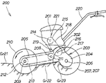
图16是这种传统的前部转动的工作设备的示意图。这种传统的前部转动的工作设备200是一种跟走式耕耘机,它包括安装在设备主体202上的发动机201以及设置在设备主体202下面的动力传动箱203。动力传动箱203包后部传动箱204和前部转动箱205,该后部传动箱204和前部转动箱205被制造成一个单件或整体单元。一对左、右行走轮207被安装在从传动箱204后部相对两侧突出的一轮轴206的两端,一转动中间副轴208被设置在传动箱204的前部。这种传统的前部转动的工作设备还包括一耕耘轴组件209,在该耕耘轴组件209上设有众多的耕耘爪210。在前部转动箱205内,一条环形链带213被缠绕和延伸在转动中间副轴208上的一驱动链轮211与耕耘轴组件209上的一从动链轮212之间。Fig. 16 is a schematic diagram of such a conventional front-rotating working device. This conventional front-rotating
在这种传统的前部转动的工作设备200中,所采用的发动机201是一种水平式发动机,该发动机具有沿侧向向外突出的一输出轴214。由于皮带218被缠绕并延伸在安装于输出轴214上的一驱动皮带轮215和安装于从传动箱204侧向突出的一输入轴216上的一从动皮带轮217之间,从而能把发动机201的输出动力传递到传动系统。即,用于把动力从发动机201传递到传动系统的-皮带传动机构221是由:安装在沿设备200宽度方向水平延伸的输出轴214上的驱动皮带轮215;安装在也沿设备200的宽度方向水平延伸的从动皮带轮217;以及缠绕在驱动轮215和从动轮217上的皮带218组成。该皮带传动机构221能通过一张力辊219被启动或被停止,其中的张力辊219用作一主离合机构。即,通过张力辊219使皮带218变紧,从而就能通过该皮带机构221实现动力传递,并且通过张力辊219使皮带218变松,从而使皮带机构221不能进行动力传递。因此,利用发动机201的输出动力,不仅可以通过轮轴206来驱动左、右行走轮207,而且还可以通过转动的中间副轴208、链213和耕耘轴组件209来驱动耕耘爪210。此外,在图16中,附图标记220表示一个手柄杆。In this conventional front-rotating
此外,在前部转动的工作设备200中,在设备主体202的宽度方向上(即,沿着贯穿图16的纸面的方向)设置四行耕耘爪210。通过所有耕耘爪210与耕耘轴组件209一起沿一个预定方向转动,工作设备200就能对土壤进行耕耘。Furthermore, in the front-rotating
在上面所描述的前部转动的工作设备200中,从侧面看,动力传递箱203的后部传动箱204和前部转动箱205被整体地连接成L形(或竖直的倒V形)。也就是说,后部传动箱204向后下方倾斜,而前部转动箱205向前下方倾斜。In the above-described front rotating
当耕耘爪210(这些耕耘爪构成了工作设备200的转动的工作单元)对土壤Gr21进行耕耘时,被耕耘出的土壤Gr22会堆积在地面上。这些堆积的土壤Gr22会撞击到后部传动箱204的底部。随着耕耘爪210的耕耘深度的增大,后部传动箱204离地面的高度就会相应地减小,如果这种趋势变得很强烈,那么,传动箱204的底部会削刮或推开这些被耕起的土壤Gr22,这常常会导致被耕耘过的土地表面变得不平整不均匀。由于存在这些不令人满意的耕耘操作或耕耘结果,因此这种传统的前部转动的工作设备200有待进一步改进(即,具有改进的余地)。When the cultivating claws 210 (the cultivating claws constituting the rotating working unit of the working device 200) cultivate the soil Gr21, the cultivated soil Gr22 is accumulated on the ground. This accumulated soil Gr 22 will hit the bottom of the
此外,象上面所描述的那样,由于后部传动箱204向后下方倾斜,因此,该后部传动箱204会阻碍被耕出的土壤Gr22,在这种情况下,这些被耕出的土壤Gr22会在传递箱204的前面堆积起来。如果传动箱204从这些堆积土壤Gr23上经过时,这些Gr23就会对所说的前部转动的工作设备200的行走造成很大的阻力。由这些堆积土壤Gr23所产生的对设备行走所造成的阻力通常是不平衡的,于是,如果这种行走阻力很大,那么,要保持工作设备200直线行走,操作人员就会受到很大的荷载;在这个方面,传统的前部转动的工作设备200也具有改进的余地。In addition, as described above, since the
此外,在这种传统的前面转动的工作设备200中,采用了水平式发动机201,皮带传动机构221被设置在水平式发动机201的右侧,左、右行走轮207被设置在皮带传动机构221两边的外侧。因此,左、右行走轮207之间的距离不可避免地会变得很大,这就会导致这种工作设备200的总体宽度很大。In addition, in this traditional front rotating working
通常,除了通常的对犁垄进行耕耘之外,在田地上的耕耘操作还包括除草操作(犁沟一犁沟耕耘),用于除去犁垄(即犁沟)之间杂草。由于在犁垄之间的犁沟的宽度通常很小,因此,利用这种总体宽度很大的工作设备进行除草操作将会具有一些局限性。Usually, in addition to the usual plowing of the furrows, the plowing operation on the field also includes a weeding operation (furrow-furrow plowing) for removing weeds between the plow ridges (ie furrows). Since the width of the furrows between the ridges is usually very small, weeding operations with such overall wide working equipment have some limitations.
发明内容Contents of the invention
鉴于前面所述的现有技术中存在的技术问题,本发明的第一个发明目的是提供这样一种类型的前部转动的工作设备,它具有一些耕耘爪,这些耕耘爪位于设备主体的前部,在设备主体上设有一些行走轮,这种设备能减小传动箱对那些由转动的工作单元所耕起的土壤造成阻碍,从而能取得令人满意的耕耘结果,并且,这种设备还排除了由被耕起的土壤所产生的行走阻力,从而显著地减小了作用于操作人员上的荷载。In view of the technical problems in the prior art described above, the first object of the present invention is to provide a type of front rotating working equipment which has cultivating claws located at the front of the main body of the equipment. There are some walking wheels on the main body of the equipment, which can reduce the obstruction of the transmission box to the soil plowed by the rotating working unit, so that satisfactory tillage results can be achieved, and this equipment Walking resistance due to tilled soil is also eliminated, thereby significantly reducing the load on the operator.
本发明的第二个发明目的是提供这样一种前部转动的工作设备,它具有一些耕耘爪,这些耕耘爪位于设备主体的前部,在设备主体上设有一些行走轮,这种设备能提高在耕耘犁沟方面的操作能力。The second invention object of the present invention is to provide such a front rotating work equipment, which has some cultivating claws, these cultivating claws are located at the front of the equipment main body, and some road wheels are provided on the equipment main body, this equipment can Improves operational ability in cultivating furrows.
为了实现上述第一个发明目的,本发明提供了一种改进的前部转动的工作设备,用于在土地上进行工作,它包括:发动机;一传动箱,被设置在发动机的下面;前部驱动轴和后部驱动轴,被可操作地与发动机相连接,并从分别从传动箱的前部和后部突出,从而,通过后部驱动轴可以驱动设置在所说发动机的后方的行走轮,通过前部驱动轴可以驱动一具有设置在所说发动机的前方的转动轴线的转动的工作单元,其中,传动箱具有大致呈平坦的底侧,该平坦的底侧设置在所说转动的工作单元的转动轴线的上方,并且大致平行于所说工作设备进行工作的土地表面延伸。In order to achieve the above-mentioned purpose of the first invention, the present invention provides an improved front rotating working equipment for working on land, which includes: an engine; a transmission box, which is arranged under the engine; the front A drive shaft and a rear drive shaft are operatively connected to the engine and protrude from the front and rear of the gearbox, respectively, so that road wheels disposed behind said engine can be driven by the rear drive shaft , a rotating working unit with a rotational axis arranged in front of the engine can be driven through the front drive shaft, wherein the gearbox has a substantially flat bottom side arranged on the rotating working unit Extends above the axis of rotation of the unit and generally parallel to the surface of the ground on which said working equipment is to be worked.
即使由转动的工作单元所耕起的土壤在土地表面上堆积至相当大的高度,本发明中的前部转动的工作设备也能防止传动箱对堆积的土壤造成不利的阻碍;也就是说,这种设备可以避免现有技术中存在的传动箱的底侧会削刮堆积土壤的技术问题。结果是,本发明中的前部转动的工作设备能确保良好的耕耘结果。Even if the soil plowed up by the rotating working unit is piled up to a considerable height on the ground surface, the front rotating working equipment of the present invention prevents the gear box from adversely hindering the piled soil; that is, This device can avoid the technical problem that the bottom side of the transmission box can scrape and accumulate soil in the prior art. As a result, the front rotating working equipment of the present invention ensures good tillage results.
此外,本发明还能可靠地防止被耕起的土壤堆积在传动箱的前面。于是,能一直避免传动箱从堆积的土壤上经过,因此,能减小对工作设备行走所造成的阻力。由于可以避免不平衡的行走阻力,因此,在使设备保持所期望的线性行走时,能有效地减小作用于操作人员上的荷载。In addition, the present invention reliably prevents plowed soil from accumulating in front of the transmission case. As a result, the transmission box can always be prevented from passing over the accumulated soil, and therefore, the resistance to the running of the work equipment can be reduced. Since the unbalanced walking resistance can be avoided, the load acting on the operator can be effectively reduced when the equipment is kept in the desired linear walking.
在一个优选的实施例中,传动箱的底侧具有相对于土地表面沿工作设备的向后方向逐渐向下倾斜的前部,和从所说的前部的后端连续的且平行于土地表面延伸的后部。由于传动箱的底侧是平坦的并且相对于要被耕耘的土地表面向后下方倾斜,因此,该工作设备能利用传动箱的底侧适当地使被耕耘过的土壤变平整,从而能改善耕耘的结果。此外,由于传动箱的底侧大致平行于土地表面并且稍微沿后下方倾斜,因此,当传动箱接触到被耕起的且堆积起来的土壤时,工作设备能容易地爬过被耕起的土壤。In a preferred embodiment, the bottom side of the transmission box has a front portion that is gradually downwardly inclined relative to the ground surface in the rearward direction of the working equipment, and a continuous and parallel to the ground surface from the rear end of said front portion. Extended rear. Since the bottom side of the transmission case is flat and slopes backward and downward relative to the surface of the ground to be plowed, the work equipment can use the bottom side of the transmission case to properly level the plowed soil, thereby improving tillage the result of. In addition, since the bottom side of the transmission case is generally parallel to the ground surface and slopes slightly downwardly along the rear, the work equipment can easily climb over the plowed soil when the transmission case contacts the plowed and accumulated soil .
在本发明的另一个优选实施例中,所说发动机是直立式发动机,该直立式发动机具有发动机主体和从该发动机主体向下突出的一输出轴;一传动箱,被设置在直立式发动机的下面,从而在工作设备的前后方向上具有相对大的尺寸,并且在工作设备的宽度方向上具有相对小的尺寸,该传动箱具有多个中间轴,这些中间轴在工作设备的宽度方向上水平延伸并且沿着所说工作设备的前后方向顺序地设置;左、右行走轮,被连接到从传动箱的后端部的两侧沿侧向突出的一轮轴或驱动轴的两端部上;一转动的工作单元,被设置在传动箱的前面。通过利用这种输出轴向下突出的直立式发动机,就能显著地减小工作设备的总体宽度。此外,由于传动箱被设置在直立式发动机的下面,因此,用于把动力从发动机传递到传动系统的一动力传递机构不会沿工作设备的宽度方向突出。此外,由于与传统的工作设备相比,在本发明在工作设备的前后方向上传动箱具有更大的尺寸,在工作设备的宽度方向上具有更小的尺寸,因此,可以减小工作设备的总体宽度。这些结构使得被连接在传动箱后端部的轮轴上的左行走轮和右行走轮之间的距离能根据需要被减小,于是,就可以减小这种前部转动的工作设备的总体宽度。因此,能够方便地把这种工作设备放置在田地的犁垄之间的狭窄的犁沟上,从而能有效地在沿着犁沟行走的同时在狭窄的犁沟上进行工作,于是就能提高这种工作设备在狭窄空间操作的能力,例如在犁沟上进行除草操作。In another preferred embodiment of the present invention, said engine is an upright engine, which has an engine body and an output shaft protruding downward from the engine body; a transmission box is arranged on the upright engine Next, so as to have a relatively large size in the front-rear direction of the work equipment and a relatively small size in the width direction of the work equipment, the transmission case has a plurality of intermediate shafts which are horizontal in the width direction of the work equipment extending and sequentially arranged along the front-rear direction of said work equipment; left and right traveling wheels are connected to both ends of a wheel shaft or drive shaft protruding laterally from both sides of the rear end of the transmission case; A rotating working unit is arranged in front of the gearbox. By utilizing such an upright engine with the output shaft protruding downward, the overall width of the work equipment can be significantly reduced. In addition, since the transmission case is provided under the vertical engine, a power transmission mechanism for transmitting power from the engine to the transmission system does not protrude in the width direction of the work equipment. In addition, since the transmission box has a larger size in the front-rear direction of the working equipment and a smaller size in the width direction of the working equipment in the present invention, compared with the conventional working equipment, the size of the working equipment can be reduced. overall width. These structures make it possible to reduce the distance between the left road wheel and the right road wheel connected to the wheel shaft at the rear end of the transmission box as required, so that the overall width of the front rotating working equipment can be reduced . Therefore, it is possible to conveniently place the working equipment on the narrow furrow between the plow furrows of the field, thereby effectively working on the narrow furrow while walking along the furrow, thus improving the The ability of this work equipment to operate in confined spaces, such as weeding operations on furrows.
附图说明Description of drawings
下面将只通过举例的方式并参照附图来详细地描述本发明的一些优选的实施例,在这些附图中:Some preferred embodiments of the invention will be described in detail below, by way of example only, with reference to the accompanying drawings, in which:
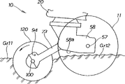
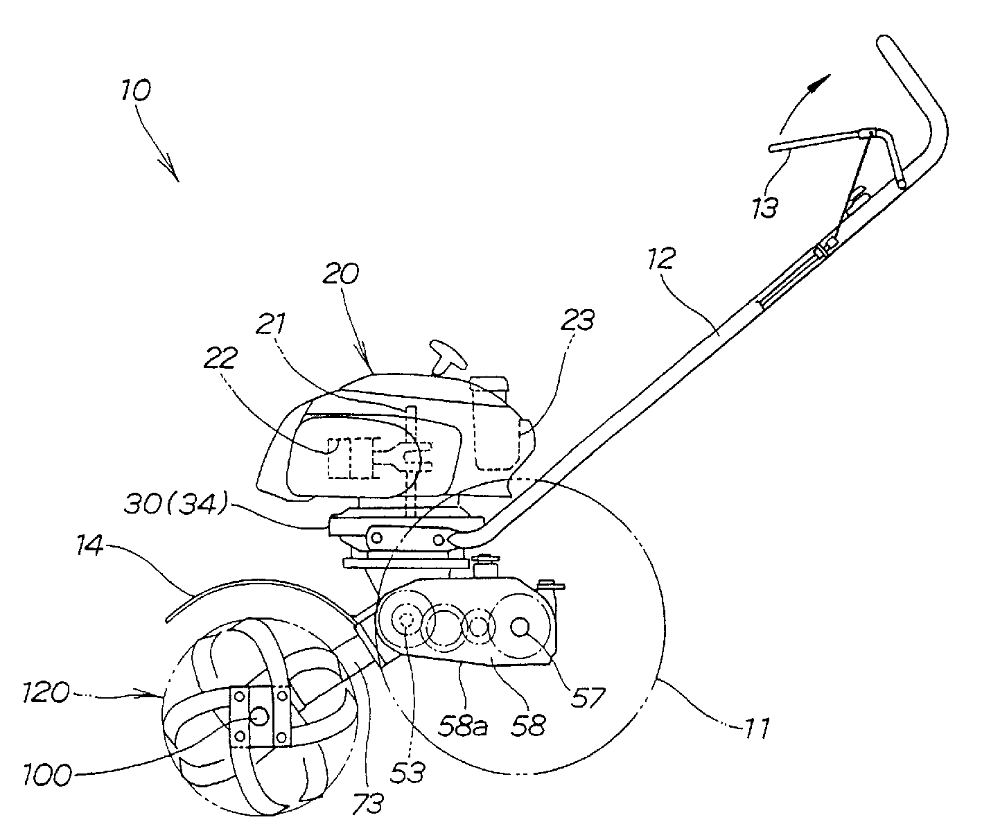
图1是根据本发明的一优选实施例的前部转动的工作设备的左视图;Fig. 1 is a left side view of a front rotating working device according to a preferred embodiment of the present invention;
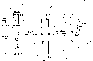
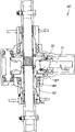
图2是图1所示的前部转动的工作设备的剖面图,图中具体地表示出了发动机、主离合机构和传动箱;Fig. 2 is a cross-sectional view of the front rotating working equipment shown in Fig. 1, in which the engine, the main clutch mechanism and the transmission case are specifically shown;
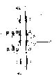
图3是本发明的这个优选实施例中所采用的主离合机构的剖面图;Fig. 3 is the sectional view of the main clutch mechanism adopted in this preferred embodiment of the present invention;
图4是主离合机构的平面图;Fig. 4 is the plan view of main clutch mechanism;
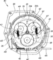
图5是沿图2中的5-5线的剖面图;Fig. 5 is a sectional view along line 5-5 in Fig. 2;
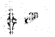
图6是沿图2中的6-6线的剖面图;Fig. 6 is a sectional view along line 6-6 in Fig. 2;
图7是本发明中的前部转动的工作设备的前视图;Fig. 7 is the front view of the working equipment that the front part rotates among the present invention;
图8A和图8B是表示本发明的优选实施例中所采用的转动工作单元的示意图;Fig. 8 A and Fig. 8 B are the schematic diagrams that represent the rotary working unit adopted in the preferred embodiment of the present invention;
图9是表示本发明的优选实施例中所采用的耕耘动力传递机构的示例性工作过程的示意图;Fig. 9 is a schematic diagram showing an exemplary working process of the cultivating power transmission mechanism adopted in the preferred embodiment of the present invention;
图10是表示耕耘动力传动机构的示例性的另一种工作过程的示意图;Fig. 10 is a schematic diagram showing another exemplary working process of the cultivating power transmission mechanism;
图11是表示耕耘动力传动机构的示例性的另一种工作过程的示意图;Fig. 11 is a schematic diagram showing another exemplary working process of the cultivating power transmission mechanism;
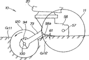
图12是本发明中的前部转动的工作设备的示例性的工作过程示意图,图中具体地表示出了当转动的工作单元沉陷至中等耕耘深度时的工作过程;Fig. 12 is a schematic diagram of an exemplary working process of the front rotating working equipment in the present invention, specifically showing the working process when the rotating working unit sinks to a medium tilling depth;
图13是本发明中的前部转动的工作设备的另一个示例性的工作过程示意图,图中具体表示出了当转动的工作单元沉陷至一个很大的耕耘深度时的工作过程;Fig. 13 is another exemplary working process schematic diagram of the front rotating working equipment in the present invention, specifically showing the working process when the rotating working unit sinks to a large tilling depth;
图14是前部转动的工作设备的另外一个示例性的工作过程示意图;Fig. 14 is another exemplary working process schematic diagram of the front rotating working equipment;
图15是前部转动的工作设备的再一个示例性的工作过程示意图;Fig. 15 is another exemplary schematic view of the working process of the front rotating working equipment;
图16是传统的前部传动的工作设备的示意图。Fig. 16 is a schematic diagram of conventional front-drive working equipment.
具体实施方式Detailed ways
应当注意,在所有的附图中,附图标记“CL”表示沿本发明中的工作设备的主体的宽度方向上的中心线。It should be noted that in all the drawings, reference numeral "CL" denotes a center line along the width direction of the main body of the working equipment in the present invention.
图1是根据本发明的一个实施例的前部转动的工作设备的左视图。这个前部转动的工作设备10被制造成一个小型的跟走式(或自推进式)耕耘机,它包括:传动箱58,其构成设备主体,并且具有连接在其上的左、右行走轮(图中只表示出了左行走轮)11;以及一转动的工作单元120,被设置在所说传动箱58的前面。FIG. 1 is a left side view of a front swivel working device according to one embodiment of the present invention. This front
具体地说,前部转动的工作设备10是一种跟走式耕耘机,其中,左、右行走轮11可转动地与传动箱58相连接,行走轮11和转动的工作单元120都由安装在传动箱58上的同一发动机20驱动。更具体地说,在图1中,传动箱58被设置在发动机20的下面,并且把一主离合机构30夹设在传动箱58和发动机20之间,输出轴53和57分别从传动箱58的前部和后部的两侧朝侧向突出。转动的工作单元120由前部输出轴(即转动的中间轴)53驱动,而左、右行走轮11由后部输出轴(即轮轴)57驱动。这样,就能沿着传动箱58的后部的两侧设置行走轮11,并且能把转动的工作单元120设置在传动箱58的前面。Specifically, the working
发动机20,作为工作设备10的驱动源,是一种直立式发动机,该发动机20具有输出轴(曲柄轴)21,该输出轴21大致朝竖直方向,从发动机20的主体向下突出。发动机20还包括大致沿水平方向延伸的一汽缸22以及临近发动机的后端的一油箱23。The
工作设备10还包括一操作手柄12,该操作手柄12从主离合机构30的一离合箱34的后端部延伸,并在该操作手柄12上可转动地安装有一离合杆13。离合杆13被用于操纵所说的主离合机构30。在这幅图中,附图标记14表示用于防止沙土飞散的盖板。The working
图2是工作设备10的剖面图,图中表示出了发动机20、主离合机构30和传动箱58。特别是,图2中从工作设备10的左侧表示出了发动机20的向下突出的输出轴21和一传动机构50,其中该传动机构50通过主离合机构30连接在输出轴21的下端。用螺栓把离合箱34的顶部连接到发动机20的主体25的下端,用螺栓把传动机构50的传动箱58连接到离合箱34的下端,从而使离合箱34和传动箱58用作该工作设备10的主体。FIG. 2 is a cross-sectional view of working
图3是对应于图2的剖面图,图中表示出了本发明的这个实施例中所采用的主离合机构30。主离合机构30包括:一中心齿轮31,被安装在发动机20的输出轴21上;一行星齿轮组件32,与所说的中心齿轮31相啮合;以及一内齿轮33,与所说的行星齿轮组件32相啮合。主离合机构30还离合箱34,该离合箱34容纳着中心齿轮31、行星齿轮组件32、内齿轮33、位于齿轮33和离合箱34之间的用于支撑着内齿轮33的众多滚珠35、用于锁定和松开内齿轮33的一制动器36。FIG. 3 is a sectional view corresponding to FIG. 2, showing the main
行星齿轮组件32包括:与中心齿轮31及内齿轮33相啮合的众多行星齿轮37;可转动地支撑着这些行星齿轮37的一行星支架38。行星支架38的中部具有一接头39,利用花键把该接头39与传动机构50的一输入轴51相连接。The
内齿轮33包括:与行星齿轮37相啮合的一轮齿部分33a;一圆筒形部分33b,所说的制动器36挤压着这个圆筒形部分33b。也就是说,圆筒形部分33b用作一制动鼓。The
图4是主离合机构30的平面图。如图所示,主离合机械30的制动器36包括:一固定销41,被固定到离合箱34上;一对制动靴42,被固定销41支撑着;一驱动凸轮43,用于使制动靴42相互移近或移离。主离合机构30还包括:一连杆44,与驱动凸轮43可操作地相连;以及一缆绳46,该缆绳的一端通过一张力弹簧45与所说的连杆44相连接。FIG. 4 is a plan view of the main
制动靴42通常被复位弹簧47相互拉近,每个制动靴42都具有一制动块(brake pads)48,用于压紧从而锁定内齿轮33。缆绳的另一端与离合杆13(见图1)相连接。The
下面将参照图3来描述主离合机构30的操作情况。在图3所示出的例子中,制动器36处于非制动状态,其中,内齿轮33能自由转动。当发动机20的输出轴21转动中心齿轮31时,转动着的中心齿轮31就转动行星齿轮37,在这个时候,内齿轮33可以自由转动,而行星支架38并不转动。因此,主离合机构30被保持在所谓的离合器关闭状态,在这种状态中,主离合机构30并不把发动机20的动力经过输出轴21传递给传动机构50。The operation of the main
然后,一旦操作人员通过离合杆13拉动缆绳46时,制动器36就被打开,从而使内齿轮33处于不能转动的状态。当发动机20的输出轴21转动中心齿轮31时,转动着的中心齿轮31就转动所说的这些行星齿轮37。在这个时候,内齿轮33处于一种锁定状态,不能转动,于是,行星支架38就被转动了。这样,主离合机构30就被切换到一种所谓的离合器开启状态,在这种离合器开启状态中,主离合机构30就能把发动机20的动力通过输出轴21传递到传动机构50。一旦离合杆13被松开,主离合机构30就会自动地回到所说的离合器关闭状态。Then, once the operator pulls the
现在再来参照图2,传动机构50的输入轴51被设置成与发动机20的输出轴21在竖直方向上同轴的对齐。通过设置在输入轴51下端的一驱动锥齿轮和设置在转动的中间轴53上的一第一从动锥齿轮54,就把发动机20的动力从传动机构50的输入轴51传递到转动的中间轴53。Referring now to FIG. 2 again, the
通过在工作设备10的前后方向上,沿水平方向把所说的转动的中间轴53、第一中间轴55、第二中间轴56、轮轴57按照所述的次序进行布置,并通过齿轮机构把这些轴53、55-57可操作地连接起来。对于这种结构,传动机构50的传动箱58能在前后方向上具有相对大的尺寸,并且在工作设备的宽度方向上(贯穿附图页面的方面)具有相对小的尺寸。此外,传动箱58还能具有减小的高度或较低的轮廓。On the front and rear direction of the working
传动箱58具有平坦的底侧58a,该平坦的底侧58a大致平行于要被耕耘的土地表面延伸。具体地说,如果发动机输出轴21的纵向中心线Pe垂直于平的地面,那么,传动箱58的底侧58a就大致平行于水平面Ho,该水平面Ho垂直于所说的中心线Pe且平行于平的地面。更具体地说,在图2所示的例子中,传动箱58的底侧58a具有一前半部分,该前半部分非常平缓地朝后下方倾斜;底侧58a相对于水平面Ho的倾斜角θ1约为5度。The
此外,在工作设备10中,通过一传动轴71把转动的中间轴53和转动工作单元120(见图1)可操作地相互连接,其中的传动轴71被包在圆筒箱73内,该圆筒箱73又被固定到传动箱58上。In addition, in the working
更特别地是,安装在转动的中间轴53上的第一从动锥齿轮54与安装在传动轴71上的第二从动锥齿轮72相啮合,传动轴71朝着一耕耘轴组件100向前下方延伸,通过轴承74和75把传动轴71可转动地支撑在圆筒壳73内,利用螺栓把圆筒壳73的近端固定在传动箱58的一安装座部分上。传动轴71和圆筒箱73相对于纵向中心线Pe的倾斜角约为60度。More particularly, the first driven
因为工作设备10采用上面所描述的低轮廓(低高度)的传动箱58,因此,传动箱58的底侧58a能被设置成距耕耘轴组件100有相当大的垂直距离;因此,与传统的前部转动的工作设备相比,增大了所说底侧58a距土地表面的距离。圆筒箱73连接有一容纳盖94,以便把圆筒箱73的前端封闭住。根据需要可以把该容纳盖94从圆筒箱73的前端拆去。具体地说,当容纳盖94被连接到圆筒箱73上时,在与耕耘轴组件100的两侧相间隔开的一些位置使容纳箱94的后端面与圆筒箱73的前端相邻接;因此,操作人员可根据需要对那些位置进行适当的操纵就能把容纳箱94从圆筒箱73上拆卸下来。Because
从前面描述中可以清楚地知道,在工作设备10中,直立式发动机20被设置在后部轮轴57和前部耕耘轴组件100之间,并且使工作设备的重心比传统的工作设备的重心更靠近工作设备10的前端,于是,转动的工作单元120(见图1)就能支撑更多的发动机20的重量。As can be clearly understood from the foregoing description, in the
此外,在本发明的工作设备10中,传动机构50的输入轴51被设置成与发动机20的向下突出的输出轴21在竖直方向上同轴线地对齐。另一方面,在传统的工作设备中,采用一种水平式发动机,这种水平式发动机具有沿侧向突出的输出轴,并且在发动机的输出轴和传动机构的输入轴之间缠绕并延伸着一条环形带。对于这种新的结构,本发明中的发动机20右被设置成更靠近传动箱58的上表面。与传统的工作设备相比,由于能降低发动机20的位置,因此,整个工作设备10的重心也就能被降低。Furthermore, in the working
图5是沿着图2中的5-5线的剖面图,其具体地表示出了传动箱58。在传动箱58中,第一正驱动齿轮61和第二正驱动齿轮62被安装在转动的中间轴53上,第一从动齿轮63和第二从动齿轮64以及爪形离合器65被安装在第一中间轴55上。根据操作人员对爪形离合器65所作的操纵,离合箱58就能通过第一中间轴55断开从转动的中间轴53向轮轴57的动力传送,或者通过第一中间轴55使动力从转动的中间轴53向轮轴57高速或低速地传递。图中附图标记67表示一变速杆。FIG. 5 is a cross-sectional view along line 5-5 in FIG. 2, which specifically shows the
特别是,图5表示出了传动机构50的传动箱58在前后方向上具有相对大的尺寸,而在工作设备的宽度方向上具有相对小的尺寸。由于传动箱58的宽度小,因此,图5中由虚线所表示的行走轮11能根据需要被设置成更靠近或更远离工作设备主体的宽度方向上的中心线。In particular, FIG. 5 shows that the
图6是沿着图2中的6-6线的剖面图,该图与图5相对应,并且在该图中以剖面图的形式具体地表示出了用于把耕耘动力从传动机构50传递到耕耘轴组件100的耕耘动力传递机构80。耕耘轴组件100穿过设备主体的宽度沿着水平延伸,该耕耘轴组件100包括:一主耕耘轴84、左侧空心轴85、右侧空心轴87。Fig. 6 is a sectional view along the line 6-6 in Fig. 2, which corresponds to Fig. 5, and in this figure, in the form of a sectional view, it specifically shows the The tilling
耕耘动力传递机构80包括:用于把发动机20(见图2)的动力传递到耕耘轴组件100的传动轴71;安装在传动轴71末端的第一锥齿轮81;相互平行且与第一锥齿轮81啮合的第二锥齿轮82和第三锥齿轮83;以及主耕耘轴84,所说的第二锥齿轮82就设置在该主耕耘轴上。耕耘动力传递机构80还包括:左侧空心轴85,被安装在主耕耘轴84上,相对于该主耕耘轴84可以转动,并且在该左侧空心轴上设有第三锥齿轮83;左侧齿轮86,与第三锥齿轮83分开地被设置在左侧空心轴85上。耕耘动力传动机构80还包括:右侧空心轴87,被安装在主耕耘轴84上,相对于该主耕耘轴84可以转动,使第二锥齿轮82和第三锥齿轮83被夹在左侧齿轮86和空心轴87之间;右侧齿轮88,被设置在右侧空心轴87上。此外,主耕耘轴传动机械80还包括:一副轴93,该副轴93具有左侧副齿轮91和右侧副齿轮92,并且在左侧齿轮86和右侧齿轮88之间把右侧齿轮88与左侧齿轮86机械地连接起来;以及容纳箱94,该容纳箱内至少全体地容纳着传动轴71、第一锥齿轮81至第三锥齿轮83、左侧齿轮86和右侧齿轮88,以及副轴93。The tilling
主耕耘轴84是一根沿着设备主体的宽度延伸的长的空心轴,它具有分别利用螺栓或以其它连接方式可拆卸地固定在其左端和右端的左侧反向转动套筒95和右侧反向转动套筒96。左侧空心轴85具有一左侧向前转动套筒97,该左侧向前转动套筒97通过键或类似物被连接在左侧空心轴85的左端。类似地,右侧空心轴87具有一右侧向前转动套筒98,该右侧向前转动套筒98通过键或类似物被连接在右侧空心轴87的右端。在这个图中,附图标记111至113表示径向轴承,附图标记114表示止推轴承。The main cultivating
图7是本发明的前部转动的工作设备的前视图。图7具体地表示出了沿着宽度中心线CL设置的发动机20、离合箱34、传动箱58以及圆筒箱73,并且离合箱34和传动箱58被设置在发动机20的主体宽度W1以内。Figure 7 is a front view of the front swivel working equipment of the present invention. 7 specifically shows the
转动工作单元120的众多耕耘爪包括:向前转动的耕耘爪121和122(即,向前转动的第一耕耘爪121和向前转动的第二耕耘爪122),以及反向转动的耕耘爪123。在下文中,术语“耕耘爪”概括地表示这些向前转动的第一耕耘爪121、向前转动的第二耕耘爪122以及反向转动的耕耘爪123。此外,术语“向前转动的耕耘爪”,概括地表示向前转动的第一耕耘爪121和向前转动的第二耕耘爪122。The numerous cultivating claws of the rotating working
本实施例中的转动工作单元120的特征在于:众多的向前转动的耕耘爪121和122被设置在传动箱58的宽度中央,而反向转动的耕耘爪123在设备主体的宽度方向上被设置在向前转动的耕耘爪121和122的外侧。The feature of the
特别是,转动工作单元120具有沿设备主体的宽度方向上设置的四排耕耘爪:1)被设置在左内侧的向前转动套筒97的安装板97a上的向前转动的耕耘爪121和122的第一排131(第一组耕耘爪131);2)被设置在右内侧的向前转动套筒98的安装板98a上的向前转动的耕耘爪121和122的第二排132(第二组耕耘爪132);3)被设置在左外侧的反向转动的套筒95的安装板95a上的反向转动的耕耘爪123的第三排133(第三组耕耘爪133);4)被设置在右外侧的反向转动套筒96的安装板96a上的反向转动的耕耘爪123的第四排134(第四组耕耘爪134)。In particular, the rotating working
左、右行走轮11被设置在反向转动的耕耘爪123的后侧。也就是说,左行走轮11被设置在第三组耕耘爪133的后侧,而右行走轮11被设置在第四组耕耘爪134的后侧。The left and
从前面的描述可以清楚地知道,由于本发明的工作设备10采用了直立式发动机20,并且输出轴21(见图2)被设置在设备主体的宽度方向的中部(即设置在沿宽度方向的中心线CL处),从而可以在工作设备10的宽度方向上提高重量平衡性。此外,由于直立式发动机20位于宽度中心线CL处,因此,可以通过把左、右行走轮11设置成更靠近发动机20,使得使以左、右行走轮之间以更小的间距把发动机20夹在中间,从而使左、右行走轮11更靠近宽度中心线CL。Can know clearly from foregoing description, because working
图8A和图8B表示出了本发明中所采用的转动工作单元120。具体地说,图8A是转动工作单元120的零件分解图,图8B沿图8A中的箭头“b”的方向看去所得到的视图。为了便于理解,在此省略了图6和图7中所表示出的安装板95a、96a、97a和98a以及耕耘轴100。8A and 8B show the
向前转动的耕耘爪121和122被构造成沿向前方向R1转动,该向前方向R1基本上对应于工作设备10(见图7)的行走方向Ru。而反向转动的耕耘爪123被构造成沿反向转动方向R2转动,该反向转动方向R2与向前转动方向R1基本上相反。The forward-rotating
本发明中所采用的转动工作单元120的特征在于:从侧面看时,每排中的向前转动的耕耘爪121和122被设置在相互相同的相位,类似地,从侧面看是地,每排中的反向转动的耕耘爪123被设置在相互相同的相位。这将在下面被详细描述。The feature of the
第一组耕耘爪131和第二组耕耘爪132中的每组都具有总数为四的向前转动的耕耘爪121和122,这四个耕耘爪121和122在它们各自的基部被叠合在一起,从而绕着耕耘轴组件100的轴向中心线Pf形成一种平行交叉的结构。类似地,第三组耕耘爪133和第四组耕耘爪134中的每组都具有总数为四的反向转动的耕耘爪123,这四个耕耘爪123在它们各自的基部被叠合在一起,从而绕着耕耘轴组件100的轴向中心线Pf形成一种平行交叉的结构。Each of the first group of cultivating
在图8A所示的例子中,第一组耕耘爪131由四个耕耘爪组成,即:一个向前转动的第一耕耘爪121,大致沿行走方向Ru(即朝前上方)延伸;一个向前转动的第二耕耘爪122,朝后上方延伸;另一个向前转动的第一耕耘爪121,朝后下方延伸;另一个向前转动的第二耕耘爪122,朝前下方延伸。所说的两个向前转动的第一耕耘爪121中的每一个都具有这样一个末端部分,该末端部分稍微向相邻的第二组耕耘爪132弯曲,并且也稍微沿反向转动的方向R2弯曲。所说的两个向前转动的第二耕耘爪122中的每一个都具有这样一个末端部分,该末端部分稍微向相邻的第三组耕耘爪133弯曲,并且也稍微沿反向转动的方向R2弯曲。In the example shown in Figure 8A, the first group of cultivating
从图8A看,第二组耕耘爪132被设置成与第一组耕耘爪131相对称。Seen from FIG. 8A , the second group of tilling
第三组耕耘爪133由四个反向转动的耕耘爪123组成,这四个反向转动的耕耘爪123被设置成与第一组耕耘爪131中的耕耘爪相对应,但是该第三组耕耘爪133的相位从第一组耕耘爪131的相应耕耘爪沿向前转动的方向R1偏移了约45度。每个反向转动的耕耘爪123都具有这样一个末端部分,该末端部分稍微朝相邻的第一组耕耘爪131弯曲,并且也稍微沿向前转动的方向R1弯曲。The third group of cultivating
第四组耕耘爪134被设置成与第三组耕耘爪133相对称。The fourth group of tilling
当然,第一组耕耘爪131至第四组耕耘爪134的角相位会随着耕耘轴组件100的转动(见图7)而发生变化。Of course, the angular phases of the first group of tilling
下面将参照图2、7和9至11来描述耕耘动力传动机构80的操作过程。The operation of the tilling
在图2中,利用主离合机构30、传动机构50的输入轴51、驱动锥齿轮52、第一从动锥齿轮54和第二从动锥齿轮72,把直立式发动机20的动力从输出轴21传递到传动轴71。In Fig. 2, utilize the main
图9示例性地表示出了本发明的这个实施例中所采用的耕耘动力传动机构80的操作过程。当利用发动机20使传动轴71沿一预定方向R0转动时,发动机动力就通过第一锥齿轮81、第二锥齿轮82和主耕耘轴84被传递到左侧反向转动套筒95和右侧反向转动套筒96。于是,左侧反向转动套筒95和右侧反向转动套筒96就沿着反向转动的方向R2转动。Fig. 9 has schematically shown the operating process of the cultivating
图10是示例性地表示耕耘动力传递机构80的操作过程的另一个视图。当利用发动机20使传动轴71沿预定方向R0转动时,发动机的动力还通过第一锥齿轮81、第三锥齿轮83和左侧空心轴85被传递到左侧的向前转动套筒97。于是,就使左侧的向前转动套筒97沿向前转动的方向R1转动。FIG. 10 is another view exemplarily showing the operation process of the tilling
图11是示例性地表示耕耘动力传动机构80的操作过程的另外一个视图。当利用发动机20使传动轴71沿预定方向R0转动时,发动机的动力还通过第一锥齿轮81、第三锥齿轮83、左侧空心轴85、左侧齿轮86、左侧副齿轮91、副轴93、右侧副齿轮92、右侧齿轮88和右侧空心轴87被传递到右侧的向前转动套筒98。于是,就使右侧的向前转动套筒98沿着向前转动的方向R1转动。FIG. 11 is another view exemplarily showing the operation process of the cultivating
通过这种方式,工作设备10就能利用发动机20的动力来使安装在左侧反向转动的套筒95和右侧反向转动的套筒96(见图6中的主耕耘轴84)上的反向转动的耕耘爪123、安装在左侧向前转动套筒97和右侧向前转动套筒98(见图6中的左侧空心轴85和右侧空心轴87)上的向前转动的耕耘爪121和122沿相反方向进行转动,如图7所示。In this way, the working
图12示例性地表示出了本发明中的工作设备的工作情况,该图中特别表示出了当转动工作单元120沉陷至中等的耕耘深度时的工作情况。当转动工作单元120对土壤Gr11进行耕耘时,被耕起的土壤Gr12就会堆积起来。为了解决被耕起的土壤Gr12会被堆积起来的问题,本发明中的前部转动的工作设备10采用了低轮廓的传动箱58,这种传动箱58的底侧58a大致是平坦的并且平行于土地表面Gr1。因此,即使在转动工作单元120沉陷至中等的耕耘深度的情况中由该工作单元120所耕起的土壤堆积了起来,也可防止传动箱58的底侧58a撞击被堆积起来的土壤Gr12。Fig. 12 exemplarily shows the working conditions of the working equipment of the present invention, especially the working conditions when the
图13示例性地表示出了本发明中的前部转动的工作设备10的工作情况,特别是,该图中表示出了当转动工作单元120沉陷至很大的耕耘深度时的工作情况。即使在转动单元120沉陷至很大的耕耘深度的情况中,该前部转动工作设备10也能防止传动箱58与堆积的土壤Gr12发生不希望的相互阻碍;也就是说,就以避免现有技术中存在的传动箱58的底侧58a会受到堆积土壤Gr12削刮的问题。于是,这种前部转动的工作设备10就能确保良好的耕耘结果。FIG. 13 exemplarily shows the operation of the front rotating working
此外,由于传动箱58的底侧58a大致是平坦的并且平行于土地表面Gr1,因此,就可以避免传动箱58的底侧58a会阻碍被耕起的土壤Gr12的可能性。于是,就能可靠地防止被耕起的土壤Gr12在传动箱58前面发生堆积。因此,就可以防止传动箱58在堆起的土壤上经过,从而可以减小工作设备的行走阻力。由于能避免不平衡的行走阻力,因此,在保持工作设备10沿期望的直线行走时,可以有效地减小作用于操作人员的负荷。Furthermore, since the
此外,由于传动箱58的底侧58a是平坦的,并且相对于要被耕起的土地表面朝后下方倾斜,因此,工作设备10能利用传动箱58的底侧58a适当地使被耕起的土壤Gr12变得平整,从而改善耕耘的结果。此外,由于传动箱58的底侧58a大致平行于土地表面Gr1并且向后下方倾斜,因此,当传动箱接触堆积起来的土壤时,工作设备10能容易地越过这些被耕起且堆积起来的土壤。In addition, since the
下面将参照图2、5、14和15来进一步描述工作设备10的工作情况。The operation of the working
如图2所示,工作设备10中所采用的发动机20是一种直立式发动机,该发动机的输出轴向下突出,因此,这种发动机所具有的宽度要比传统中的相应工作设备小得多。主离合机构30也被用作动力传动机构,用于把发动机20的动力传递到传递机构50。由于主离合机构30是由行星齿轮减速机构和制动器的联合组成的,因此,发动机20的输出轴21和传动机构50的输入轴51能以在竖直方向上相互对齐的方式同轴线地相互连接,并且能减小离合箱34的高度,也就是说,能把离合箱34制造成一种较低的结构。此外,用作动力传动机构的主离合机构30不会沿工作设备的宽度方向(即沿贯穿图2页面的方向)突出。而且,该传动箱58能够被形成为在工作设备10的前后方向上的尺寸相对地大,而在工作设备10的宽度方向上的尺寸相对地小。As shown in Figure 2, the
由于传动箱58的宽度小,因此,可以根据需要把图5中由虚线所表示的左、右行走轮11设置成更靠近或更远离工作设备的沿宽度方向的中心线CL。于是,就能够显著地减小被设置在传动箱58的后端部两侧附近的左、右行走轮11之间的距离,从而也就能减小工作设备10的宽度。Due to the small width of the
图14是示例性地表示前部转动的工作设备10的工作情况的另一个视图,特别是,该图中表示出了工作设备10执行普通的耕耘操作情况,其中,左、右行走轮11相互之间的间距为传统的距离W2,并且左、右行走轮处于犁垄U1两侧的犁沟U2上,以便对所说的犁垄U1进行耕耘。Fig. 14 is another view schematically showing the operation of the front rotating working
图15是示例性地表示所说的前部转动的工作设备10工作情况的另一个视图,在该图中,具体地表示出了这样一种情况,即,在这种情况中,工作设备10在一狭窄的空间内执行耕耘操作,例如在单条犁沟U3内进行耕耘操作,其中,左、右行走轮11之间被相互隔开一间距W3,其比传统的距离W2小得多的,并且左、右行走轮11处于犁沟U3上,以便在犁沟U3上进行除草操作。在这种情况中,工作设备10能容易地被放置在狭窄的犁沟U3上,以便在沿着狭窄的犁沟U3行走的同时进行工作,从而能提高工作设备10在狭窄空间内的可操作性。Fig. 15 is another view schematically showing the working condition of said front rotating working
例如,从图15可以明显地看出,通过改变行走轮11的轮毂11a在轮轴57上的轴向位置,就能调节左、右行走轮11之间的距离。如图15所示,如果减小左、右行走轮11之间的距离,那么,就可以把第三组耕耘爪133和第四组耕耘爪134从耕耘轴组件上拆去。For example, as can be clearly seen from FIG. 15 , the distance between the left and
由于左、右行走轮11之间的距离是可以调节的,因此,只利用单个工作设备10就能象图15所示那样在狭窄空间内执行耕耘操作,也能象图14那样执行普通的耕耘操作。Because the distance between the left and
按照上面所描述的方式所构造的本发明具有以下一些优点。The present invention constructed in the manner described above has the following advantages.
即使当那些由转动工作单元耕起的土壤堆积至相当大的高度时,本发明中的前部转动的工作设备也能防止传动箱与堆积的土壤发生干扰,并且能避免现有技术中存在的传动箱的底侧会削刮堆积土壤的问题。于是,本发明中的前部转动的工作设备能良好的耕耘结果。此外,本发明还能可靠地防止被耕起的土壤在传动箱的前面发生堆积。这样,就总能防止传动箱从堆积起来的土壤上经过,于是就能减小工作设备的行走阻力。由于通过这种方式能避免不平衡的行走阻力,因此,在保持工作设备沿直线行走的过程中,能有效地减小作用于操作人员的负荷。Even when the soil plowed up by the rotating working unit is piled up to a considerable height, the front rotating working equipment of the present invention can prevent the transmission box from interfering with the piled soil, and can avoid the problems existing in the prior art. The underside of the gearbox can be a problem with scraping accumulated soil. Thus, the front-rotating working equipment of the present invention enables good tillage results. In addition, the invention reliably prevents plowed soil from accumulating in front of the transmission case. In this way, it is always possible to prevent the transmission box from passing over the accumulated soil, so that the running resistance of the work equipment can be reduced. Since unbalanced walking resistance can be avoided in this way, the load acting on the operator can be effectively reduced during the process of keeping the working equipment walking in a straight line.
此外,由于采用其输出轴向下突出的直立式发动机,因此,能够显著减小工作设备的宽度。由于传动箱被设置在这种直立式发动机的下面,因此,用于把动力从发动机传递到传动系统的动力传动机构不会沿工作设备的宽度方向突出。此外,由于传动箱在工作设备的前后方向上具有相对大的尺寸,并且在工作设备的宽度方向上具有相对小的尺寸,因此,还能进一步减小工作设备的宽度。采用这种结构,就能减小左、右行走轮之间的距离,从而能减小这种前部转动的工作设备的总体宽度。由于这种工作设备具有这些优点,因此,这种工作设备能容易地被放置在狭窄的犁沟上,以便在工作设备沿狭窄的犁沟平滑地行走的同时进行工作,于是便能大大地提高这种工作设备在狭窄空间内的可操作性,例如可以在这些犁沟上进行除草。In addition, since the vertical engine whose output shaft protrudes downward is adopted, the width of the work equipment can be significantly reduced. Since the transmission case is provided under such an upright engine, the power transmission mechanism for transmitting power from the engine to the transmission system does not protrude in the width direction of the work equipment. Furthermore, since the transmission case has a relatively large size in the front-rear direction of the work equipment and a relatively small size in the width direction of the work equipment, the width of the work equipment can be further reduced. With this structure, the distance between the left and right road wheels can be reduced, thereby reducing the overall width of the front-rotating work equipment. Because this work equipment has these advantages, therefore, this work equipment can be placed on the narrow furrow easily, so that work is carried out while the work equipment walks smoothly along the narrow furrow, so just can improve greatly. The manoeuvrability of this working device in confined spaces, for example, enables weeding on these furrows.
传动箱在工作设备的前后方向上具有增大了的尺寸,这种传动箱具有减小了的高度或具有较低的轮廓。发动机能被设置成更靠近传动箱的上表面和土地表面。由于降低了整个工作设备的重心,因此同,就能提高这种前部转动的工作设备在行走时的稳定性。The gear box has increased dimensions in the front-rear direction of the working machine, the gear box has a reduced height or a lower profile. The engine can be positioned closer to the upper surface of the gearbox and the ground surface. Because the center of gravity of the entire work equipment is lowered, the stability of the front rotating work equipment can be improved while walking.
Claims (3)
Applications Claiming Priority (4)
| Application Number | Priority Date | Filing Date | Title |
|---|---|---|---|
| JP008023/2002 | 2002-01-16 | ||
| JP2002008023A JP3990572B2 (en) | 2002-01-16 | 2002-01-16 | Front rotary work machine |
| JP2002008041A JP2003204702A (en) | 2002-01-16 | 2002-01-16 | Front rotary work machine |
| JP008041/2002 | 2002-01-16 |
Publications (2)
| Publication Number | Publication Date |
|---|---|
| CN1432265A CN1432265A (en) | 2003-07-30 |
| CN1253065C true CN1253065C (en) | 2006-04-26 |
Family
ID=26625549
Family Applications (2)
| Application Number | Title | Priority Date | Filing Date |
|---|---|---|---|
| CNU032360649U Expired - Fee Related CN2696287Y (en) | 2002-01-16 | 2003-01-15 | Working equipment with front rotatable work unit |
| CNB03100637XA Expired - Fee Related CN1253065C (en) | 2002-01-16 | 2003-01-15 | Working equipment with front rotary working unit |
Family Applications Before (1)
| Application Number | Title | Priority Date | Filing Date |
|---|---|---|---|
| CNU032360649U Expired - Fee Related CN2696287Y (en) | 2002-01-16 | 2003-01-15 | Working equipment with front rotatable work unit |
Country Status (6)
| Country | Link |
|---|---|
| US (1) | US6722445B2 (en) |
| EP (1) | EP1329611B1 (en) |
| KR (1) | KR100888630B1 (en) |
| CN (2) | CN2696287Y (en) |
| ES (1) | ES2261794T3 (en) |
| TW (1) | TWI234431B (en) |
Cited By (1)
| Publication number | Priority date | Publication date | Assignee | Title |
|---|---|---|---|---|
| US9016180B2 (en) | 2002-11-01 | 2015-04-28 | Black & Decker Inc. | Tile saw |
Families Citing this family (25)
| Publication number | Priority date | Publication date | Assignee | Title |
|---|---|---|---|---|
| US4704226A (en) * | 1985-11-14 | 1987-11-03 | Texaco, Inc. | Process for thickening aqueous solutions |
| JP4180981B2 (en) * | 2003-06-13 | 2008-11-12 | 本田技研工業株式会社 | Differential |
| US6922981B1 (en) * | 2003-11-17 | 2005-08-02 | Princetree, Llc | Power equipment with a singular motor |
| US7273016B2 (en) * | 2004-05-20 | 2007-09-25 | Deere & Company | Variable speed drive for agricultural seeding machines |
| USD515592S1 (en) | 2004-09-17 | 2006-02-21 | One World Technologies Limited | Ergonomic tiller handle |
| US20070163789A1 (en) * | 2006-01-17 | 2007-07-19 | Eastway Fair Company Limited | Cultivator/tiller |
| US20080033783A1 (en) * | 2006-08-01 | 2008-02-07 | Prince Tree Llc | System and Method of Retaining Customers |
| US7621194B1 (en) | 2006-08-01 | 2009-11-24 | Hillard Tyree | Singular motor for attachment to multiple host implements |
| KR100823426B1 (en) * | 2007-01-05 | 2008-04-18 | 주식회사 아세아텍 | Clutch assembly for walking mower |
| US7866409B2 (en) | 2007-09-06 | 2011-01-11 | Honda Motor Co., Ltd. | Tilling machine transport and storage apparatuses and methods |
| US7963344B2 (en) * | 2008-09-03 | 2011-06-21 | Black & Decker Inc. | Tiller with removable battery |
| US8627897B2 (en) | 2008-09-03 | 2014-01-14 | Black & Decker Inc. | Tiller housing |
| US8434563B2 (en) | 2010-02-26 | 2013-05-07 | Schiller Grounds Care, Inc. | Device for cultivating soil or brushing debris |
| US8499848B2 (en) | 2011-08-05 | 2013-08-06 | Techtronic Outdoor Products Technology Limited | Gas tiller |
| US8939241B2 (en) | 2012-01-12 | 2015-01-27 | Cnh Industrial America Llc | Front mounted agricultural work vehicle power takeoff system |
| SE538344C2 (en) * | 2012-08-31 | 2016-05-24 | Rolf Mattson | Handheld tiller with interchangeable drive unit |
| KR101318016B1 (en) * | 2012-10-16 | 2013-10-14 | 김영훈 | The prefabricated muti-tasking device |
| US9167737B2 (en) | 2013-05-22 | 2015-10-27 | Carts & Tools Technology, Inc. | Garden implement |
| EP3051030A3 (en) * | 2015-01-09 | 2016-10-19 | Emec S.R.L. | Apparatus for burying cables, pipes and the like, and operating method thereof |
| CN105052258A (en) * | 2015-07-17 | 2015-11-18 | 重庆嘉木机械有限公司 | Lightweight micro-tiller capable of being converted into mower |
| CN105075440B (en) * | 2015-08-06 | 2017-05-31 | 贵州黔沣农业科技发展有限公司 | A kind of Multifunction portable agricultural machine |
| US10875109B1 (en) | 2018-04-30 | 2020-12-29 | Kreg Enterprises, Inc. | Adaptive cutting system |
| KR102254268B1 (en) * | 2019-03-07 | 2021-05-24 | 경북대학교 산학협력단 | weeding device of field furrow |
| KR102421503B1 (en) | 2020-06-08 | 2022-07-15 | 주식회사 태광공업 | Rotary for farming |
| CN112161032A (en) * | 2020-11-05 | 2021-01-01 | 湖南秀林机械有限公司 | Two-wheel-drive mini-tiller gearbox |
Family Cites Families (23)
| Publication number | Priority date | Publication date | Assignee | Title |
|---|---|---|---|---|
| GB847474A (en) * | 1957-12-09 | 1960-09-07 | J E Shay Ltd | Improvements in or relating to power-driven horticultural tools |
| US4133390A (en) * | 1976-03-11 | 1979-01-09 | Magna American Corporation | Tine arrangements for garden tillers |
| JPS543732A (en) * | 1977-06-11 | 1979-01-12 | Kubota Ltd | Transmission structure for four-wheel drive tractor |
| DE3027553C2 (en) * | 1979-08-02 | 1982-02-11 | Honda Giken Kogyo K.K., Tokyo | Vertical motor cultivator |
| US4567949A (en) * | 1983-02-14 | 1986-02-04 | Roper Corporation | Soil tilling machine with transmission having three drive trains |
| US4519459A (en) * | 1983-03-31 | 1985-05-28 | Magna American Corporation | Power drive rear tine tiller with reversing gear transmission for the tines |
| JPS59210803A (en) * | 1983-05-13 | 1984-11-29 | 本田技研工業株式会社 | Plowing machine |
| US4699219A (en) * | 1984-04-02 | 1987-10-13 | Garden Way Incorporated | Cultivator drag bar and mounting therefor |
| GB2180604B (en) * | 1985-09-11 | 1990-03-28 | Kubota Ltd | Transmission system for vehicle having planetary gear type forward and backward drive switching apparatus |
| CA1287147C (en) * | 1985-10-24 | 1991-07-30 | Hiromu Fujimoto | Tractor equipped with working implements |
| US4838357A (en) * | 1986-04-04 | 1989-06-13 | Mitsubishi Agricultural Machinery Co., Ltd. | Soil tilling machine |
| US4856264A (en) * | 1987-01-26 | 1989-08-15 | Honda Giken Kogyo Kabushiki Kaisha | Hydraulic transmission apparatus |
| US4895210A (en) * | 1988-12-12 | 1990-01-23 | Witzel H D | Clutch-brake steering for small agricultural machines |
| FR2689363B1 (en) * | 1992-01-14 | 1995-01-13 | Honda Motor Co Ltd | Rotor tiller with tillage teeth. |
| JPH0672164A (en) * | 1992-08-25 | 1994-03-15 | Honda Motor Co Ltd | Power transmission for self-traveling type working machine |
| JPH06125603A (en) * | 1992-10-20 | 1994-05-10 | Kubota Corp | Walk-behind mobile agricultural machine |
| US5320451A (en) * | 1993-03-19 | 1994-06-14 | Garvey John R | Cable laying attachment for tiller |
| JPH07115801A (en) * | 1993-10-26 | 1995-05-09 | Kubota Corp | Rotary tiller |
| US5713420A (en) * | 1995-08-28 | 1998-02-03 | Garden Way, Incorporated | Convertible garden tiller |
| DE19621702A1 (en) * | 1995-11-16 | 1997-05-22 | Guenter Schuladen | Portable or wheel driven electric soil cultivator |
| US6488101B1 (en) * | 1999-09-02 | 2002-12-03 | Honda Giken Kogyo Kabushiki Kaisha | Tiller |
| JP2001271903A (en) * | 2000-01-17 | 2001-10-05 | Honda Motor Co Ltd | Power transmission device for work equipment |
| US6338209B1 (en) * | 2000-04-11 | 2002-01-15 | Mcclure David | Tilling machine, method of use and method of gardening |
-
2003
- 2003-01-07 ES ES03000211T patent/ES2261794T3/en not_active Expired - Lifetime
- 2003-01-07 TW TW092100260A patent/TWI234431B/en not_active IP Right Cessation
- 2003-01-07 EP EP03000211A patent/EP1329611B1/en not_active Expired - Lifetime
- 2003-01-09 US US10/339,073 patent/US6722445B2/en not_active Expired - Fee Related
- 2003-01-15 CN CNU032360649U patent/CN2696287Y/en not_active Expired - Fee Related
- 2003-01-15 CN CNB03100637XA patent/CN1253065C/en not_active Expired - Fee Related
- 2003-01-16 KR KR1020030002927A patent/KR100888630B1/en not_active Expired - Fee Related
Cited By (3)
| Publication number | Priority date | Publication date | Assignee | Title |
|---|---|---|---|---|
| US9016180B2 (en) | 2002-11-01 | 2015-04-28 | Black & Decker Inc. | Tile saw |
| US9044878B2 (en) | 2002-11-01 | 2015-06-02 | Black & Decker Inc. | Tile saw |
| US9073236B2 (en) | 2002-11-01 | 2015-07-07 | Black & Decker Inc. | Tile saw |
Also Published As
| Publication number | Publication date |
|---|---|
| US6722445B2 (en) | 2004-04-20 |
| KR20030062379A (en) | 2003-07-25 |
| EP1329611A3 (en) | 2003-12-10 |
| CN1432265A (en) | 2003-07-30 |
| TWI234431B (en) | 2005-06-21 |
| EP1329611B1 (en) | 2006-04-19 |
| ES2261794T3 (en) | 2006-11-16 |
| CN2696287Y (en) | 2005-05-04 |
| TW200302044A (en) | 2003-08-01 |
| KR100888630B1 (en) | 2009-03-17 |
| EP1329611A2 (en) | 2003-07-23 |
| US20030132011A1 (en) | 2003-07-17 |
Similar Documents
| Publication | Publication Date | Title |
|---|---|---|
| CN1253065C (en) | Working equipment with front rotary working unit | |
| CN1275503C (en) | Tillage machine with following back part | |
| CN2621388Y (en) | Cultivator | |
| CN1251568C (en) | rotary tiller | |
| CN201869526U (en) | Ditching and ridging machine adopting mode of firstly ploughing and then ripping | |
| CN2324752Y (en) | Power driven machine for weeding | |
| CN104602508A (en) | Vertical tine tiller | |
| CN2650466Y (en) | Multifunctional unitary ploughing and rotary tilling machine | |
| CN1265695C (en) | Multifunctional Farmland Work Machine | |
| JP3990572B2 (en) | Front rotary work machine | |
| JP3997350B2 (en) | Walk-type field cultivator | |
| JP3062795B2 (en) | Coaxial forward / reverse working machine | |
| JP4116154B2 (en) | Management work machine | |
| JP3565937B2 (en) | Coaxial forward / reverse working machine | |
| JP2687115B2 (en) | Coaxial forward / reverse working machine | |
| JP3977933B2 (en) | Tillage rotary for management work | |
| JP2004000024A (en) | Tilling machine | |
| JP2003189702A (en) | Tilling machine | |
| JPH0471481B2 (en) | ||
| JP2003204703A (en) | Front rotary work machine | |
| JP2003204702A (en) | Front rotary work machine | |
| JP2006262756A (en) | Rotary tilling apparatus | |
| JP2007043920A (en) | Farming machine |
Legal Events
| Date | Code | Title | Description |
|---|---|---|---|
| C06 | Publication | ||
| PB01 | Publication | ||
| C10 | Entry into substantive examination | ||
| SE01 | Entry into force of request for substantive examination | ||
| C14 | Grant of patent or utility model | ||
| GR01 | Patent grant | ||
| CF01 | Termination of patent right due to non-payment of annual fee |
Granted publication date: 20060426 Termination date: 20160115 |
|
| EXPY | Termination of patent right or utility model |