CN1246260A - Method and device for directional wireless communication - Google Patents
Method and device for directional wireless communication Download PDFInfo
- Publication number
- CN1246260A CN1246260A CN 97181797 CN97181797A CN1246260A CN 1246260 A CN1246260 A CN 1246260A CN 97181797 CN97181797 CN 97181797 CN 97181797 A CN97181797 A CN 97181797A CN 1246260 A CN1246260 A CN 1246260A
- Authority
- CN
- China
- Prior art keywords
- mentioned
- signal
- website
- auxiliary
- intensity
- Prior art date
- Legal status (The legal status is an assumption and is not a legal conclusion. Google has not performed a legal analysis and makes no representation as to the accuracy of the status listed.)
- Pending
Links
Images


Landscapes
- Mobile Radio Communication Systems (AREA)
Abstract
A method of directional radio communication between a first station and a second station comprises the following steps. A first signal transmitted by a second station is received at a first station. The first signal may be received from a plurality of different directions. A primary beam direction is determined in which the first station receives the first signal. A plurality of beam directions for transmitting the transmit beam are defined at the first station. The respective beam directions are selectable. The primary beam direction and at least one other secondary beam direction are selected for determination at the first station. At least one secondary beam direction is adjacent to the determined primary beam direction. A second signal is transmitted from the first station to the second station in the selected beam direction.
Description
The present invention relates to the method and apparatus of directional radio communication, wherein the signal between first base station and second base station is only to send on the direction of determining.Especially, but not only in this, the present invention can be used for using the cellular communications network of space division multiple access.
In the cellular communications network of current realization, a basic transceiver station (BTS) specifies mobile radio station (MS) to send signal in order to give, and this base transceiver station (BTS) generally sends signal at the whole sub-district or the cell sector of this base transceiver station service.And space division multiple access (SDMA) system has been proposed now.In a space division multi-access, the mobile radio station of the appointment that basic transceiver station can be in whole sub-district or cell sector sends signal, and only can send signal along the beam direction from the mobile radio station received signal.The SDMA system can also allow the definite direction from the mobile radio station received signal in basic transceiver station.
The SDMA system can obtain some advantages that surpass existing system.Particularly, because the beam that BTS sends is only sending on a specific direction, and the direction relative narrower, the power of transceiver can be focused on the narrow beam.Can determine that this method all can obtain signal to noise ratio preferably for the signal of basic transceiver station transmission and the signal of basic transceiver station reception.In addition, stand firm to the result of characteristic, can improve the signal to noise ratio of the signal of basic transceiver station reception as basic transceiver.And on sending direction, the directional characteristic of BTS allows on concentration of energy to a narrow beam, and the signal that makes BTS send can arrive distance mobile radio station far away, and power level is lower than the requirement of conventional BTS.This allows mobile radio station in the far local operate as normal in distance basic transceiver station, thereby means the sub-district that can increase Cellular Networks or the area of cell sector.Result as increasing the sub-district area can reduce required base station number, thereby reduce network charges.The SDMA system generally needs some antenna elements so that obtain required transmission and a plurality of different beam directions of received signal.Provide a plurality of antenna elements to increase the sensitivity of BTS received signal.This means that bigger sub-district area can not produce adverse influence from the mobile radio station received signal to BTS.
The SDMA system also can increase the capacity of system, promptly increased the quantity of the mobile radio station that system can support simultaneously.Its reason is the directional characteristic of communication, and this characteristic means that BTS can pick up less interference from the mobile radio station other sub-district of using same frequency.When communicating by letter with the MS of an appointment in the related cell, BTS can produce less interference to the mobile radio station in other sub-district of using same frequency.
At last, the SDMA system allows to use simultaneously identical frequency to send signal to two or more different mobile radio stations that are positioned on the diverse location of same sub-district.This has increased the transmission quantity that Cellular Networks can be born greatly.
Can realize SDMA by analog-and digital-Cellular Networks, and can introduce multiple existing, such as GSM, DCS1800, TACS, the standard of AMPS and NMT.The SDMA system also can with such as time division multiple access (TDMA), code division multiple access (CDMA), other existing multiple access technology of frequency division multiple access (FDMA) technology is used.
A problem of SDMA system is the direction that needs to determine to send to mobile radio station signal.In some cases, can use the beam of a relative narrower to send signal from a basic transceiver station to a mobile radio station.Therefore, need the quite accurately direction of this mobile radio station of assessment.As everyone knows, the signal from mobile radio station arrives BTS along several paths usually.These paths are commonly referred to as multipath.Because this multipath effect, basic transceiver standing-meeting receives the specification signal that mobile radio station sends from a more than direction.
Another problem is to determine that according to the uplink signal that BTS receives from mobile radio station BTS sends the direction of signal to mobile radio station.But be different from BTS sends frequency from signal to mobile radio station to the frequency that BTS sends down link signal from mobile radio station.The frequency of using in up link and the down link signal different mean that the behavior of channel in the uplink direction is different from the behavior of the channel in the down link direction.Like this, the optimal direction of determining at the uplink signal optimal direction of down link signal always not.
Thereby a target of certain embodiments of the invention is to overcome these difficulties.
According to a first aspect of the invention, wherein provide a method of carrying out directional radio communication between first website and second website, the step that this method comprises has:
Receive first signal that above-mentioned second website sends at above-mentioned first website, wherein can receive above-mentioned first signal from a plurality of different directions;
Determine that above-mentioned first website receives the main beam direction of above-mentioned first signal;
In the beam direction of a plurality of transmission emission of first site definitions beam, wherein above-mentioned each beam direction is optional;
Determine other auxiliary beam direction of main beam direction and at least one in that above-mentioned first stop point selection is above-mentioned, above-mentioned at least one auxiliary beam direction is adjacent with above-mentioned definite main beam direction, and upwards states secondary signal of second website transmission from above-mentioned first website on above-mentioned selected beam direction.
By using this method, increased the probability that second website receives the signal that first website sends.Because the intensity of the secondary signal that second website sends on auxiliary direction depends on a parameter of first signal that receives on this direction, if second website receives a relative stronger signal at least one auxiliary direction, can at least one auxiliary direction, send a relative stronger signal so to first website.
In fact, first website can receive first signal on a plurality of directions.Have only one to be selected as definite main direction in these directions.Can select to determine main direction by some different modes.For example, determine that main direction can be selected as first website receives first signal with ceiling capacity or intensity direction.Alternatively, determine that main direction can be selected as the direction that first website at first receives first signal.This direction is corresponding to the signal that arrives along shortest path, and this path can be the circuit in direct projection path.
In one embodiment of the invention, first signal comprises a known data sequence, and this method also comprises and carries out relevant treatment so that obtain the step of channel impulse response receiving data-signal and known data sequence.In an optimum embodiment, the duplicate that this locality that receives a data-signal and a given data sequence is produced carries out relevant treatment.Channel impulse response is used to determine that direction is main direction.For example, can determine channel impulse response at each channel corresponding with the different directions that should receive first signal.Like this, the channel impulse response that is received is the measurement of the existing quantity of desired signal that first website is received.Can be compared to each other some parameter of the channel impulse response of each channel so that determine that direction provides ceiling capacity or minimum delay for first signal.Signal with minimum delay is the signal that first website at first receives.
At least one auxiliary direction can be included in the direction of determining main direction both sides.
The intensity of the above-mentioned secondary signal on above-mentioned at least one auxiliary direction is preferably lower than or equals in the intensity of determining the secondary signal on the main direction.
Said method preferably includes the step in the beam direction of an emission of a plurality of transmissions of first site definitions beam, and wherein each above-mentioned beam direction all is separately optionally.The transmitted power of each beam direction can be confirmable separately, and wherein the transmitted power of the beam on that or each auxiliary direction is lower than the transmitted power on the direction of main beam.
In one embodiment of the invention, the intensity of secondary signal and the above-mentioned ratio of determining the intensity of secondary signal on the main direction on above-mentioned at least one auxiliary direction determine that above-mentioned the ratio of the intensity of first signal that main direction receives is directly proportional with first website from the intensity of first signal of above-mentioned at least one auxiliary direction reception with first website.These two ratios preferably equate.
If be significantly smaller than the intensity of determining first signal that receives on the main direction in the intensity of first signal that receives on above-mentioned at least one auxiliary direction, preferably only determine to send above-mentioned secondary signal from first website to second website on the main direction above-mentioned.If but the intensity of first signal that receives on above-mentioned definite main direction and above-mentioned at least one auxiliary direction is basic identical, stipulate that then first website sends secondary signal on definite main direction, and on above-mentioned at least one auxiliary direction, send this signal with essentially identical signal strength signal intensity.Like this, when definite majority is when determining that main direction receives first signal, only on this direction, send secondary signal.If but determine to receive first signal with essentially identical intensity from two or more directions, then on these two or more directions, send secondary signal with essentially identical intensity.Between these two qualification situations, also have other situation certainly, wherein can be less than the intensity of determining the secondary signal on the main direction in the intensity of the secondary signal on above-mentioned at least one auxiliary direction.
The intensity of the secondary signal that first website sends at least one above-mentioned definite main direction and at least one auxiliary direction preferably depends on the intensity of first signal that first website receives on respective direction.At least one determines that the intensity of the secondary signal on main direction and above-mentioned at least one auxiliary direction can depend on first website mean intensity of a plurality of targeting signals that receive from second website.In an optimum embodiment, depend on the intensity of above-mentioned first signal that receives on the respective direction an above-mentioned intensity of determining the secondary signal on main direction and above-mentioned at least one auxiliary direction, and depend on the mean intensity of a plurality of targeting signals that above-mentioned first website receives from above-mentioned second website in other above-mentioned intensity of determining the secondary signal on main direction and above-mentioned at least one auxiliary direction on respective direction.Be preferably based on the intensity of first signal in the intensity of determining the secondary signal on the main direction, and preferably determine the intensity of the secondary signal at least one auxiliary direction according to the mean intensity of a plurality of targeting signals that receive from second website.Like this, when receiving signal, can revise the power on the main direction, attempt to catch up with the channel variation that influences the path between first and second websites fast.On the contrary, the power at least one auxiliary direction can respond to variation more slowly, attempts to increase the level of the signal that second website receives.Can increase by second website like this and receive probability from the signal of first website.
A beam on above-mentioned or another at least one auxiliary direction can with determine that a beam that defines on the main beam direction is overlapping.In another suggestion, above-mentioned or another at least one auxiliary beam can be overlapping with half expanded-angle of determining main beam.
Whether this method preferably includes determines in the distance of second website and first website less than the step of a predetermined value, and less than situation under upwards state second website with the expanded-angle of relative broad from above-mentioned first website and send secondary signal.Particularly, resulting total expanded-angle is more preferably greater than resulting expanded-angle when the distance between first website and second website is higher than predetermined value, and other auxiliary direction of main direction and at least one is used to send above-mentioned signal.
According to a second aspect of the invention, carry out one first website of directional radio communication with one second mobile radio station, said apparatus comprises:
Receive the acceptor device of first signal of above-mentioned second website transmission, can receive above-mentioned first signal from a plurality of different directions;
Determine definite device of the main direction of above-mentioned first signal of reception;
From the sender device of first website to a secondary signal of second website transmission, above-mentioned sender device sends an emission beam on a plurality of beam directions, and wherein each above-mentioned beam direction is optional;
Control the control device of above-mentioned sender device, wherein above-mentioned control device is controlled above-mentioned sender device and send above-mentioned secondary signal to above-mentioned website on definite main beam direction and at least one auxiliary beam direction, and above-mentioned at least one auxiliary direction is adjacent with definite main direction.
Acceptor device and sender device can comprise an aerial array, and this array is used to provide a plurality of signal beams on a plurality of different directions.Aerial array can comprise a phasing antenna array, perhaps can comprise a plurality of separately, divides other that antenna element of a beam is provided on the direction of a definition.Can provide two independent arrays, received signal and another sends signal.Alternatively, can provide an independent array to be used for sending and received signal.
Control device preferably is used to according to the power level of determining the above-mentioned signal on above-mentioned definite beam direction and above-mentioned at least one auxiliary direction at the relative energy level of first signal of determining to receive on beam direction and at least one other beam direction.Above-mentioned control device can be determined the relative energy level by a part that receives first signal and the known version or the part wherein of this signal are carried out relevant treatment.Be appreciated that first signal can comprise or comprise a training sequence, this sequence is one and carries out the given data sequence of relevant treatment with one of training sequence with reference to version, and training sequence is not distorted so that determine channel impulse response.This information can be used to determine relative power level and can be used to determine main direction.
Sender device can be used to provide an emission beam on a plurality of beam directions, wherein each beam direction is separately optionally.
The transmitted power of each beam direction is preferably confirmable separately, and wherein the transmitted power of the beam on that or each auxiliary direction is less than the transmitted power on the main beam direction.
The present invention is specially adapted to cellular communications network.In such network, first website can be a basic transceiver station, and second website then is a mobile radio station.But be appreciated that embodiments of the invention go for any type, such as the cordless communication network of PCN (dedicated communications network) or similar network.
In order to understand the present invention better and to realize the present invention, can be described by way of example with reference to accompanying drawing now, wherein:
Fig. 1 shows the structure chart of a basic transceiver station (BTS) and relevant cell sector thereof;
Fig. 2 shows the sketch at an aerial array and basic transceiver station;
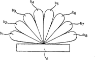
Fig. 3 shows the holding beam pattern that the aerial array of Fig. 2 provides;
Fig. 4 shows the structure chart of the digital signal processor of Fig. 2;
Fig. 5 illustrates the channel impulse response of four channels in eight channels.
At first, wherein show three cell sectors 2 of a sub-district 3 of definition cellular mobile telephone network with reference to Fig. 1.Three cell sectors 2 provide service by corresponding basic transceiver station (BTS) 4.Provide three branches other basic transceiver station 4 in same position.Each BTS4 has a transceiver at a corresponding transmission and received signal in three cell sectors 2.The basic transceiver station of a special use is provided respectively for each cell sector 2 like this.Thereby each BTS4 can communicate by letter with the mobile radio station (MS) such as the mobile phone that is arranged in respective cell sector 2.
In the environment of a GSM (global system for mobile communications) network, present embodiment has been described.In gsm system, use frequency/time division multiple access F/TDMA system.Mode with pulse train sends data between BTS4 and MS.It is the training sequence of given data sequence that data pulse string comprises one.The purpose of training sequence will be described below.In this frequency range, send each data pulse string by a predetermined time slot in the designated frequency band.Use a directional antenna array to allow to realize space division multiple access.Like this, in an embodiment of the present invention, will be by designated frequency band, assigned timeslot and assigned direction send each data pulse string.Can be at passing through designated frequency band, relevant channel of specific data pulse train definition that assigned timeslot and assigned direction send.As described below, in certain embodiments of the present invention, by similar frequency bands, the directions that identical time slot but two are different send identical data pulse strings.
Fig. 2 shows a structure chart as the aerial array 6 of the BTS4 of transceiver.Be to be understood that 6 of arrays shown in Figure 2 serve in three cell sectors 2 shown in Figure 1.Two aerial arrays 6 are other two cell sectors, 2 services in addition.Aerial array 6 has 8 antenna element a
1... a
8Each antenna element a
1... a
8Between be spaced apart half wavelength, and be arranged in delegation along a vertical line.Each antenna element a
1... a
8Be used to send and received signal, and can have the structure of any appropriate.Each antenna element a
1... a
8Can be a dipole antenna, patch antenna (patch antenna) or other suitable antenna arbitrarily.8 antenna element a
1... a
8Defined a battle array control antenna 6 mutually jointly.
As everyone knows, each antenna element a of phase battle array control antenna 6
1... a
8Be provided the same signal that will send to a mobile radio station MS.But be provided for respective antenna unit a
1... a
8The phase place of signal offseted each other.Be provided for respective antenna unit a
1... a
8Phase difference between signals produced a directional transmissions pattern.Like this, from the signal of BTS4 only in the cell sector 2 relevant, to send with array 6 along some direction.The directional transmissions pattern that array 6 is realized is phase deviation each other and by each antenna element a
1... a
8The long mutually interference that occurs between the signal that sends and the result of destructive interference.In this, with reference to Fig. 3, this figure illustrates the directional transmissions pattern that realizes by aerial array 6.Can in graphic 8 directions of Fig. 3, provide a beam b on any one direction by control antenna array 6
1... b
8For example, can the control antenna array 6 at beam b
5Or b
6Direction on send signal to MS.As described below, also can on more than one beam direction, send signal simultaneously by control antenna array 6.For example, can be at beam b
5And b
6Send signal on the both direction of definition.
The structure of 8 possible beam directions that Fig. 3 just can realize by aerial array 6 is represented.But in fact, between adjacent beams, have overlapping to guarantee that aerial array 6 provides service for all cell sectors 2.
By a Butler matrix circuit 8 each antenna element of control a
1... a
8On the relative phase of the signal that provides, make it possible to send signal along the beam direction of expectation.Butler matrix circuit 8 provides a phase deviation function like this.Butler matrix circuit 8 has 8 input 10a-h and 8 outputs from BTS4, and wherein each output all is output to each antenna element a
1... a
8The signal that each input 10a-h receives comprises the data pulse string that will send.8 input 10a-h all represent to send the beam direction of specific data pulse train.For example, when Butler matrix circuit 8 received a signal on the first input 10a, Butler matrix circuit 8 offered each antenna element a to the signal on the input 10a with the phase difference that requires
1... a
8To produce beam b
1Thereby, at beam b
1Direction on send data pulse string.Similarly, the signal that provides on input 10b causes at beam b
2Direction on produce a beam, or the like.
As mentioned above, the antenna element a of aerial array 6
1... a
8Send signal from a MS received signal and to a MS.The signal of a MS transmission usually can be by 8 antenna element a
1... a
8Receive.But at each antenna element a
1... a
8Have a phase difference between each signal that receives.Thereby Butler matrix circuit 8 can be according to each antenna element a
1... a
8The relative phase of the signal that receives is determined the beam direction of received signal.Thereby Butler matrix circuit 8 has 8 inputs, and the signal for each antenna element receives all has one from antenna element a
1... a
8Input.Butler matrix circuit 8 also has 8 output 14a-h.14a-14h is all corresponding to a particular beam direction that can receive the specific data pulse train in each output.For example, if aerial array 6 at beam b
1Direction on receive a signal from a MS, then Butler matrix circuit 8 can be exported received signal on output 14a.At beam b
2Direction on the signal that receives can cause on output 14b from Butler matrix circuit 8 output received signals, or the like.In a word, Butler matrix circuit 8 can be at antenna element a
1... a
88 versions that are offset each other of last reception same signal.According to relative phase skew, Butler matrix circuit 8 is determined to have received the direction of above-mentioned received signal and is specified signal of output on the output 14a-h according to the direction of received signal at one.
Be to be understood that under some environment,, suppose that reflection has the expanded-angle of relative broad between MS and BTS4 because signal reflex seems and can transmit simultaneously from more than one beam direction from the independent signal of a MS or data pulse string.Butler matrix circuit 8 can provide a signal on each output 14a-h, and each output is corresponding to each beam direction that specification signal or data pulse string occur.Like this, can Butler matrix circuit 8 more than one output 14a-h on identical data pulse string is provided.But the signal on each output 14a-h can postpone each other if having time.
Each output 14a-h of Butler matrix circuit 8 is connected in the input of a corresponding amplifier 16 that amplifies received signal.For Butler matrix circuit 8 each output 14a-h an amplifier 16 is provided.Then handle amplifying signal by a corresponding processor 18, this processor processing amplifying signal makes BTS4 can handle this signal so that the frequency of received signal is reduced to base band frequency.For this reason, processor 18 is removed carrier frequency component from input signal.And, for each output 14a-h of Butler matrix circuit 8 provides a processor 18.Then the received signal with analog form is converted to digital signal by a modulus (A/D) transducer 20.8 A/D converters 20 are provided, and each output 14a-h of Butler matrix circuit 8 all has one.Then by corresponding input 19a-h digital signal being input to a digital signal processor 21 carries out follow-up processing.
Digital signal processor 21 also has 8 output 22a-h, and each output is all exported one and indicated to be sent to a digital signal of specifying the signal of MS.Selected output 22a-h indicates to send the beam direction of signal.This digital signal is converted to analog signal by a digital-to-analogue (D/A) transducer 23.For digital signal processor 21 each output 22a-h a digital to analog converter 23 all is provided.Then processor 24 Analog signals, this processor are that analog signal that a handle will send is modulated to the modulator on the carrier frequency.Before processor 24 processing signals, signal is on the base band frequency.Then 26 pairs of signals that produced of an amplifier amplify and are delivered on the corresponding input 10a-h of Butler matrix circuit 8.For digital signal processor 21 each output 22a-h a processor 24 and an amplifier 26 all are provided.
Fig. 4 referring now to graphical figure signal processor 21.Should be appreciated that graphic each module needn't be corresponding to each unit that embodies an actual digital signal processor 21 of the present invention among Fig. 4.Particularly, among Fig. 4 graphic each module corresponding to the performed various functions of digital signal processor 21.In one embodiment of the invention, realized digital signal processor 21, and same unit can be carried out several functions by integrated circuit to small part.
Each signal that digital signal processor 21 receives on corresponding input 19a-h is imported into corresponding channel impulse response (CIR) estimator module 30.CIR estimator module 30 comprises the memory capacity of the channel impulse response of storage estimation.CIR estimator module also comprises the memory capacity of interim storage received signal.Channel impulse response estimator module 30 is used to estimate the channel impulse response of the channel of corresponding input 19a-h.As mentioned above, at the frequency range by selecting, the specific data pulse train that the beam direction of distributed time slot and received signal sends can define a relevant channel.Butler matrix circuit 8 is determined the beam direction of received signals, makes the signal that receives on the input 19a of digital signal processor mainly represent the signal that receives from the direction of beam b1, or the like.Should be appreciated that and specifying the signal that receives in the input also can be included in the sidelobe of the signal that receives in the adjacent input.
Each data pulse string that sends to BTS4 from mobile radio station MS comprises a training sequence TS.But the training sequence TS that BTS4 receives
RXBe subjected to the influence of noise and multipath effect, wherein multipath effect produces interference between the phase ortho position of training sequence.A kind of interference in back is known as intersymbol interference.TS
RXAlso be subjected to the influence of the interference of other mobile radio station, for example be positioned at other sub-district or cell sector, use can cause the mobile radio station of the same frequency of combined channel interference.Be appreciated that from the specification signal of MS and can arrive BTS along path more than one, and aerial array 6 can from an assigned direction detect specification signal more than one version.CIR estimator module 30 handles are from input 19a received training sequence TS
RXBe stored in a reference TS in the data memory 32
REFCarrying out crosscorrelation handles.Reference TS
REFIdentical with the initial training sequence that sends of mobile radio station.In fact received training sequence TS
RXBe a signal that is modulated onto carrier frequency, and reference TS
REFIn data storage 32, be stored as a bit sequence.Correspondingly, before carrying out crosscorrelation, the reference of storage is similarly modulated.In other words, the not distortion version of BTS4 reception distortion training sequence and training sequence is carried out relevant treatment.In an optional embodiment of the present invention, before it being carried out relevant treatment, received training sequence is carried out demodulation with reference.In this case, reference can have identical form with positive received training sequence once more.In other words, reference is not modulated.
Reference TS
REFWith received training sequence TS
RXAll have length L, and can be 26 positions corresponding to L data bit.Received training sequence TS
RXDistributing the definite position in the time slot can be uncertain.This is because the distance between mobile radio station MS and the BTS4 can have influence on the data pulse string of MS transmission in the position of distributing in the time slot.For example, if a mobile radio station MS is far away relatively apart from BTS4, compare with the mobile radio station MS situation nearer apart from BTS4 so, training sequence can appear on the position after having distributed in the time slot.
Consider received training sequence TS
RXThe uncertainty of the position in distributed time slot is used reference TS
REFTo received training sequence TS
RXCarrying out the n correlations handles.Usually, n can be 7 or 9.N is an odd number preferably.The n correlations can be obtained on the relevant both sides in maximum usually and carry out.Received training sequence TS
RXAt reference TS
REFRelative position be offset a position between each serial correlation.Each position is equivalent in the training sequence and represents that postpones a section.Received training sequence TS
RXWith reference TS
REFThe tap of this relevant channel impulse response of expression of each independent relevant generation.N independent tap sequence of relevant generation with n value.
Referring now to Fig. 5, the figure shows channel impulse response corresponding to 4 channels in 8 of 8 direction in spaces possible channels.In other words, Fig. 5 shows the channel impulse response corresponding to 4 channels of a specific data pulse train that receives from mobile radio station on 4 directions in 8 beam directions, and data pulse string is on the frequency range and time slot of appointment.The x axle of each legend is the measurement to time delay, and the y axle is the measurement to relative power.Each line (or tap) expression that marks among the figure is received, corresponding to the multi-path signal of specifying correlation delay.Each legend has n line or tap, and one of them tap is relevant corresponding to each.
According to the channel impulse response of estimation, can determine that training sequence is in the position of distributing in the time slot.When obtaining received training sequence TS
RXWith reference TS
REFBetween optimum can obtain maximum values of tap when relevant.
At each channel, CIR estimator module 30 is also determined the continuous tap that 5 (or other suitable quantity) arbitrarily provide ceiling capacity.Calculate the ceiling capacity of an allocated channel according to following mode:
Wherein h represents by received training sequence TS
RXWith reference TS
REFThe tap amplitude that obtains of crosscorrelation.CIR estimator module 30 is by using a kind of ceiling capacity of sliding window setting technique estimation allocated channel.In other words, CIR estimator module 30 is considered 5 adjacent values at every turn and is calculated energy according to these 5 values.Select 5 consecutive values of given ceiling capacity to represent the impulse response of this channel.
Energy can be counted as the measurement from the intensity of a desired signal of specifying MS that BTS4 is received on an assigned direction.Carry out this process at all 8 channels, these channels represent to receive 8 different directions of identical data pulse train.The signal that receives with ceiling capacity the path of process to the decay minimum of this signal.
An analysis module 34 is provided, the ceiling capacity that this module stores CIR estimator module 30 calculates at respective channel according to 5 consecutive values, and CIR estimator module 30 selects these 5 consecutive values to represent channel impulse response.Analysis module 34 also can be analyzed channel impulse response that CIR estimator module 30 determines so that determine the minimum delay.This delay is to received training sequence TS
RXIn the measurement that distributes the position in the time slot, thereby be relative measurement to signal propagation distance between mobile radio station and BTS4.Channel with minimum delay has the signal of the beeline of passing.This beeline can be represented the circuit in the direct projection path between mobile radio station MS and the BTS4 in some cases.
Analysis module 34 is used to determine the starting position of window, and this window is determined five values that ceiling capacity is provided.Time between then beginning according to a reference point and window is determined time delay.This reference point can be that all received training sequences in each branch began by relevant common time, and this time is corresponding to window edge the earliest or a similar common point of all branches.For the accurately relatively various delays of different channels, adopt a public timing ratio, this ratio depends on the synchronizing signal that BTS4 provides for the TDMA pattern of control operation.In other words, received training sequence TS
RXDistributing position in the time slot is measurement to time delay.Should be appreciated that in known gsm system, the delay of an allocated channel for the timing advance information calculations is provided.Timing advance information is used to guarantee that the signal that mobile radio station sends to BTS drops on in its distributed time slot.Can determine timing advance information according to relative delay and the current timing advance information calculated.If mobile radio station is away from the base station, then BTS can instruct MS send its data pulse string in certain time, this time ratio time that mobile radio station MS sends data pulse string under more near the situation of BTS more early.
The analysis result that each analysis module 34 draws is imported into a comparison module 36.Comparison module 36 compares ceiling capacity of determining at each channel and the delay that also can relatively determine at each channel.Comparison module 36 is at the data designated pulse train, and the frequency range of appointment and the time slot of appointment determine to have the channel of ceiling capacity.This means and to determine to receive the specific data pulse train beam direction of strong version.This direction is the main beam direction that will be used for by BTS to MS transmission signal.Comparison module 36 also can determine to have the channel in minimum delay.In other words, also can determine to have the channel of the data pulse string that passes through shortest path.This beam direction can be compared module 36 and be elected to be definite main beam direction.
Like this, comparison module 34 is selected from mobile radio station and is received the specific data pulse train beam direction of strong version, and this beam is main beam.Then comparison module is selected the beam on main beam both sides, and these two beams are auxiliary beams.For example, if beam b
4Be selected as main beam, then two auxiliary beams are beam b
3And b
5
Comparison module 36 is also determined the power level of main beam.Can select the power level of main beam by some kinds of different modes.For example, postponing to select a relatively low power under the less relatively situation,, can select relatively large power if delay is longer relatively.The power level of determining main beam can consider that also MS is used for sending to BTS the current timing advance information of signal.Optionally, the energy of determining according to the channel impulse response of the signal that receives from main beam direction can be used to determine the power level of the signal on the main beam direction.These are open-loop methods.But any method that other is suitable for also can be used to determine the power level of main beam.For example, can report the power level of the signal on definite main beam direction according to the power measurement that BTS receives at corresponding MS.This is a closed-loop policy.
Comparison module 36 also calculates the power level that is used to auxiliary beam, and this beam is used to send signal to MS.If main beam is the i beam, then i beam can have a power P that has been selected as above-mentioned power
iAuxiliary beam can be i+1 and i-1 beam, i.e. two beams on main beam both sides.The power of i-1 beam is defined by P
i/ a, and the power of i+1 beam is defined by P
i/ b, wherein a and b are all more than or equal to 1.
Have some kinds different, can select the mode of the value of a and b.In one embodiment, a and E
i/ E
I-1Be directly proportional, wherein E
iBe the energy that the channel impulse response according to the signal that receives from MS on the i beam direction calculates, E
I-1It is the energy that the channel impulse response according to the signal that receives from mobile radio station on the i-1 beam direction calculates.Similarly, b and E
i/ E
I+1Be directly proportional, wherein E
I+1It is the energy that the channel impulse response according to the signal that receives from mobile radio station on the i+1 beam direction calculates.
Should be appreciated that the E value that to calculate each beam in the manner described above.
If E
I-1And E
I+1Be significantly smaller than E
i, BTS4 then only sends signal to mobile radio station MS on the direction of main beam.If E
I-1And E
I+1Be similar to E
i, then main beam has identical power with two auxiliary beams.But the power of main beam can be greater than the power of auxiliary beam as a rule.
Thereby comparison module 36 provides an output to generation module 38, and which beam this output indication is used to send signal from BTS4 to MS, and indication is used to the suitable power of each beam.Power level can be an absolute power level, and the information about the relative power level of the signal on main and auxiliary beam direction perhaps can only be provided.
In certain embodiments, main beam can be first or the 8th beam, and beam b
1Or b
8In these cases, only provide an independent auxiliary beam.
In one embodiment of the invention, the calculating energy according to an independent data pulse string that receives from MS on the given beam direction calculates a and b.Alternatively, can calculate a and b according to the average computation energy meter of N preamble pulse string.For example N can be 5.For the i-1 beam, should calculate the energy of all 5 lead data pulse trains that on the i-1 beam direction, receive according to corresponding channel impulse response.Then calculate a average energy value that can be used to determine a.Similarly, can calculate b according to N the preamble pulse string that receives from the i+1 beam direction.In one embodiment, can be according to the power of the main beam i of mode correction of pulse train one by one.In other words, determine power on the main beam according to the targeting signal that on main beam direction, receives from mobile radio station.Like this, can be at the power of the main beam of each pulse train correction, thus attempt to catch up with the variation that influences the path between BTS and the MS fast, can control auxiliary beam power but utilize by the information of N preamble pulse serial connection receipts.Like this, auxiliary beam can attempt increasing the level of the signal that mobile radio station receives, and is used as diversity paths, the path change between this path slow response BTS and the MS.
In another embodiment of the present invention, a and b have predetermined fixed value, and these values are fixed to the power level of auxiliary beam on the predetermined percentage of power level of main beam.
It is far away relatively apart from BTS that the foregoing description is particularly useful for mobile radio station, and distance therebetween is greater than the situation of a critical distance.This critical radius depends on the environment of each discrete sub-district, and nearly 0.5 to 1km usually.When the distance between BTS and the MS during greater than critical distance, the most of energy that receives from MS is by on the less relatively beam direction.Particularly, energy mainly concentrates on one, on two or three beam directions.But the distance between mobile radio station and BTS is during less than critical distance, and the expectation energy of reception can be distributed on the bigger beam of quantity usually.Correspondingly, in an embodiment of the present invention, only to use main and auxiliary beam under greater than the situation of critical distance in the distance between MS and the BTS4.When the distance between MS and the BTS during less than critical distance, BTS4 can pass through the more relatively beam of quantity, and for example 4 or more beam send signal to MS.Employed power level can be lower than the power that is used for main beam when the distance between MS and the BTS4 during greater than critical distance usually when the expanded-angle by a relative broad sends.
Can use any suitable method to determine that whether distance between MS and the BTS is greater than critical distance.In one embodiment, comparison module 36 compares the channel impulse response that obtains on each possible direction.If most received energies are distributed on three or the beam direction still less, suppose that then distance between BTS and the MS is greater than critical distance.Alternatively, if most received energy is distributed on 4 or the more direction, suppose that then distance between MS and the BTS is less than critical distance.
Comparison module also can use timing advance information to determine whether the distance between MS and the BTS is greater than or less than critical distance.Owing to provide than the more accurate result of the method that proposes previously, this method is optimum in certain embodiments of the present invention.
The foregoing description used one independent, have the simulation beam maker of Butler matrix form.But revise among the embodiment at one of the foregoing description, can use two beam makers, for example Butler matrix and spatial complementary matrix thereof.Two beam makers are complementary under the situation that produces the staggered beam in space that almost covers same area.Then can produce main beam, and generate auxiliary beam by complementary beam maker by a beam maker.Like this, auxiliary beam is overlapping with main beam basically.Overlapping scope is far longer than by independent beam and generates two resulting scopes of adjacent beams that produce.
Should be appreciated that in an embodiment of the present invention three beams can all have different power levels.But can select in certain embodiments, the power of two auxiliary beams always to have identical value.
Generation module 38 is responsible for generation will be from the signal of digital signal processor 21 outputs.Generation module 38 has one and indicates to send to the speech of mobile radio station MS and/or the input 40 of information.Generation module 38 is responsible for the speech or the information that send to mobile radio station MS are encoded, and comprises a training sequence and a synchronizing sequence in signal.Module 38 also is responsible for producing modulation signal.According to signal that produces and the beam direction of determining, generation module 38 provides signal on the corresponding output 22a-h of digital signal processor 21.Generation module 38 also provides an output 50, and this output is used to the amplification that control amplifier 24 is provided, thereby guarantees that the signal on the main and auxiliary beam direction has the power level of requirement.
The output of channel impulse response module 30 also is used to signal balanced and that coupling receives from mobile radio station MS.Particularly, the effect of the intersymbol interference that is produced by multipath propagation in the received signal can be eliminated or alleviate to matched filter (MF) and equalizer module 42.Should be appreciated that matched filter (MF) and equalizer module have the input (not shown) of a reception from the received signal of MS.Speech that the responsible MS of recovery sends and/or the recovery module of information 44 receive the output of each modules 42.The step that the recovery module is finished comprises carries out the demodulation sign indicating number to signal.Speech that recovers or information are output in the output 48.
Though should be appreciated that and realized the foregoing description in the GSM cellular communications networks, the present invention can also be used to other digital cellular communications communication network and analogue cellular network.The foregoing description has used the phased array with 8 unit.Array certainly has the unit of any amount.Alternatively, phased array can be replaced by discrete directional antenna, and each antenna is all launched beam on an assigned direction.Under the situation of needs, the Butler matrix circuit can be by other suitable phase-shift circuit replacement arbitrarily.The Butler matrix circuit is a simulation beam maker.Certainly use the simulation beam maker of a digital beam maker DBF or any other adequate types.According to the signal that offers each unit,, also can array of controls produce beam more than 8 even under the situation of having only 8 unit.
Also can provide a plurality of phased array.Phased array can provide the beam of varying number.When the expanded-angle of a broad of needs, use cellular array with lesser amt, when the beam of a relative narrower of needs, use cellular array with larger amt.
Being appreciated that the foregoing description is described as from the Butler matrix circuit provides 8 outputs.Should be appreciated that in fact and in each output of Butler matrix, can export several different channels simultaneously.Those channels can have different frequency ranges.The channel of different time-gap also can be provided in corresponding output.Though independent amplifier has been described in the front, processor, in fact analog to digital converter and digital to analog converter can provide above-mentioned all parts by an independent unit with a plurality of input and output.
Be to be understood that embodiments of the invention have the application that is not limited only to cellular communications network.For example, embodiments of the invention can be used in any environment that needs directional radio communication.For example, can in PMR (ad Hoc wireless network) or similar network, use this technology.
Claims (19)
1. carry out the method for directional radio communication between one first website and one second website, the step that this method comprises has:
Receive first signal that above-mentioned second website sends at above-mentioned first website, wherein can receive above-mentioned first signal from a plurality of different directions;
Determine that above-mentioned first website receives the main beam direction of above-mentioned first signal;
In the beam direction of a plurality of transmission emission of first site definitions beam, wherein above-mentioned each beam direction is optional;
Determine other auxiliary beam direction of main beam direction and at least one in that above-mentioned first stop point selection is above-mentioned, above-mentioned at least one auxiliary beam direction is adjacent with above-mentioned definite main beam direction, and upwards states secondary signal of second website transmission from above-mentioned first website on above-mentioned selected beam direction.
2. the method for claim 1 is wherein according to the intensity of the above-mentioned signal of determining in a parameter of first signal that receives on above-mentioned at least one auxiliary direction to send on above-mentioned at least one auxiliary direction.
3. method as claimed in claim 2, wherein at least one auxiliary direction comprises the beam direction of determining main direction both sides.
4. as the described method of claim 1,2 or 3, the direction of strong version that wherein receives first signal is determined to be above-mentioned main direction.
5. as the described method of claim 1,2 or 3, the direction that wherein at first receives a version of first signal is determined to be main direction.
6. as any one described method in the claim of front, wherein be less than or equal to the intensity of the secondary signal that on above-mentioned definite main direction, sends in the intensity of the secondary signal that sends on above-mentioned at least one auxiliary direction.
7. as any one described method in the claim of front, the intensity of secondary signal and the above-mentioned ratio of determining the intensity of secondary signal on the main direction on wherein above-mentioned at least one auxiliary direction determine that above-mentioned the ratio of the intensity of first signal that main direction receives is directly proportional with first website from the intensity of first signal of above-mentioned at least one auxiliary direction reception with first website.
8. as any one described method in the claim of front, if wherein be significantly smaller than the intensity of first signal that on definite main direction, receives, so only determine that above-mentioned upwards stating second website from above-mentioned first website on the main direction sends above-mentioned secondary signal in the intensity of first signal that receives on above-mentioned at least one auxiliary direction.
9. as any one described method in the claim of front, if wherein the intensity of first signal that receives on above-mentioned definite main direction and above-mentioned at least one auxiliary direction is basic identical, stipulate that then first website sends secondary signal on above-mentioned definite main direction, and on above-mentioned at least one auxiliary direction, send this signal with essentially identical signal strength signal intensity.
10. as the described method of any claim in front, wherein first website depends on the intensity of first signal that above-mentioned first website receives on respective direction at least one above-mentioned intensity of determining the secondary signal that sends on main direction and at least one auxiliary direction.
11. as the described method of any claim in front, wherein at least one above-mentioned intensity of determining the secondary signal on main direction and above-mentioned at least one auxiliary direction depends on the mean intensity of a plurality of targeting signals that first website receives from above-mentioned second website on respective direction.
12. as the described method of any claim in front, comprising determining in the distance of second website and first website whether less than the step of a predetermined value, and less than situation under upwards state second website with the expanded-angle of relative broad from above-mentioned first website and send secondary signal.
13. as the described method of any claim in front, wherein above-mentioned first website is a basic transceiver station in the beehive network system.
14. as the described method of any claim in front, wherein above-mentioned second website is a mobile radio station.
15. as any described method of augmenting on the claim 2 of claim in front, wherein the transmitted power of each above-mentioned beam direction can be confirmable separately, and wherein the transmitted power of the beam on that or each auxiliary direction is lower than the transmitted power on the direction of main beam.
16. carry out first website of directional radio communication with one second mobile radio station, said apparatus comprises:
Receive the acceptor device of first signal of above-mentioned second website transmission, can receive above-mentioned first signal from a plurality of different directions;
Determine definite device of the main direction of above-mentioned first signal of reception;
From the sender device of first website to a secondary signal of second website transmission, above-mentioned sender device sends an emission beam on a plurality of beam directions, and wherein each above-mentioned beam direction is optional;
Control the control device of above-mentioned sender device, wherein above-mentioned control device is controlled above-mentioned sender device and send above-mentioned secondary signal to above-mentioned website on definite main beam direction and at least one auxiliary beam direction, and above-mentioned at least one auxiliary direction is adjacent with definite main direction.
17. first website as claimed in claim 16, wherein above-mentioned acceptor device and above-mentioned sender device comprise an aerial array, and this array is used to provide a plurality of signal beams on a plurality of different directions.
18. as claim 16 or 17 described first websites, wherein control device is used to determine to be chosen in according to a parameter of first signal that receives the intensity of the above-mentioned secondary signal on the above-mentioned auxiliary direction on above-mentioned at least one auxiliary direction.
19. as described first website of claim 16,17 or 18, wherein above-mentioned controller control sender device makes in the transmitted power of assisting the beam on direction or each the auxiliary direction less than the transmitted power on the main beam direction.
Priority Applications (1)
| Application Number | Priority Date | Filing Date | Title |
|---|---|---|---|
| CN 97181797 CN1246260A (en) | 1997-02-13 | 1997-02-13 | Method and device for directional wireless communication |
Applications Claiming Priority (1)
| Application Number | Priority Date | Filing Date | Title |
|---|---|---|---|
| CN 97181797 CN1246260A (en) | 1997-02-13 | 1997-02-13 | Method and device for directional wireless communication |
Publications (1)
| Publication Number | Publication Date |
|---|---|
| CN1246260A true CN1246260A (en) | 2000-03-01 |
Family
ID=5178224
Family Applications (1)
| Application Number | Title | Priority Date | Filing Date |
|---|---|---|---|
| CN 97181797 Pending CN1246260A (en) | 1997-02-13 | 1997-02-13 | Method and device for directional wireless communication |
Country Status (1)
| Country | Link |
|---|---|
| CN (1) | CN1246260A (en) |
Cited By (2)
| Publication number | Priority date | Publication date | Assignee | Title |
|---|---|---|---|---|
| CN1307807C (en) * | 2001-01-30 | 2007-03-28 | 皇家菲利浦电子有限公司 | Radio communication system |
| CN107358393A (en) * | 2011-03-17 | 2017-11-17 | 伊普若沃讷恩斯有限公司 | For protecting the method and system of movable property |
-
1997
- 1997-02-13 CN CN 97181797 patent/CN1246260A/en active Pending
Cited By (2)
| Publication number | Priority date | Publication date | Assignee | Title |
|---|---|---|---|---|
| CN1307807C (en) * | 2001-01-30 | 2007-03-28 | 皇家菲利浦电子有限公司 | Radio communication system |
| CN107358393A (en) * | 2011-03-17 | 2017-11-17 | 伊普若沃讷恩斯有限公司 | For protecting the method and system of movable property |
Similar Documents
| Publication | Publication Date | Title |
|---|---|---|
| CN1123261C (en) | Method and device for directional wireless communication | |
| US6289005B1 (en) | Method and apparatus for directional radio communication | |
| CN1143408C (en) | radio antenna system | |
| AU736743B2 (en) | Method and apparatus for directional radio communication | |
| US7310537B2 (en) | Communication on multiple beams between stations | |
| US6321082B1 (en) | Method and apparatus for directional radio communication | |
| CN103765794B (en) | Device and method for selecting optimal beam in wireless communication system | |
| KR101563469B1 (en) | Mobile station and Method for controlling the mobile station performing random access with switched beamforming, and Method for controlling base station | |
| US6751206B1 (en) | Method and apparatus for beam switching in a wireless communication system | |
| CN1118152C (en) | Radio communication device and transmitting power control method | |
| CN1153373C (en) | Overlapping slot transmission using phased arrays | |
| AU725235B2 (en) | Method and apparatus for directional radio communication | |
| CN103875195A (en) | Method and apparatus for transmitting and receiving information for random access in wireless communication system | |
| JP2005531987A (en) | A system that efficiently provides coverage of sectorized cells. | |
| EP1518331A1 (en) | System for efficiently covering a sectorized cell utilizing beam forming and sweeping | |
| CN1135882C (en) | Method and apparatus for directional radio communication | |
| JP2002232350A (en) | Wireless communication method and wireless communication system using variable beam direction antenna | |
| CN1246260A (en) | Method and device for directional wireless communication | |
| KR100464332B1 (en) | Apparatus and method for forming beam of array antenna in mobile communication system | |
| CN1246206A (en) | Method and device for directional wireless communication | |
| CN1251531C (en) | Method and device of signal transmitting of antenna array to downstream channel in mobile communication system | |
| CN1221543A (en) | Method and device for directional radio communication | |
| CN1221544A (en) | Method and apparatus for directional radio communication | |
| CN1121805C (en) | Method and apparatus for directional radio communication |
Legal Events
| Date | Code | Title | Description |
|---|---|---|---|
| C06 | Publication | ||
| PB01 | Publication | ||
| C10 | Entry into substantive examination | ||
| SE01 | Entry into force of request for substantive examination | ||
| AD01 | Patent right deemed abandoned | ||
| C20 | Patent right or utility model deemed to be abandoned or is abandoned |