CN116075986A - Electrical connector system with post terminal body - Google Patents
Electrical connector system with post terminal body Download PDFInfo
- Publication number
- CN116075986A CN116075986A CN202180056853.5A CN202180056853A CN116075986A CN 116075986 A CN116075986 A CN 116075986A CN 202180056853 A CN202180056853 A CN 202180056853A CN 116075986 A CN116075986 A CN 116075986A
- Authority
- CN
- China
- Prior art keywords
- spring
- male terminal
- connector assembly
- terminal body
- electrical connector
- Prior art date
- Legal status (The legal status is an assumption and is not a legal conclusion. Google has not performed a legal analysis and makes no representation as to the accuracy of the status listed.)
- Pending
Links
Images


Classifications
-
- H—ELECTRICITY
- H01—ELECTRIC ELEMENTS
- H01R—ELECTRICALLY-CONDUCTIVE CONNECTIONS; STRUCTURAL ASSOCIATIONS OF A PLURALITY OF MUTUALLY-INSULATED ELECTRICAL CONNECTING ELEMENTS; COUPLING DEVICES; CURRENT COLLECTORS
- H01R13/00—Details of coupling devices of the kinds covered by groups H01R12/70 or H01R24/00 - H01R33/00
- H01R13/44—Means for preventing access to live contacts
-
- H—ELECTRICITY
- H01—ELECTRIC ELEMENTS
- H01R—ELECTRICALLY-CONDUCTIVE CONNECTIONS; STRUCTURAL ASSOCIATIONS OF A PLURALITY OF MUTUALLY-INSULATED ELECTRICAL CONNECTING ELEMENTS; COUPLING DEVICES; CURRENT COLLECTORS
- H01R13/00—Details of coupling devices of the kinds covered by groups H01R12/70 or H01R24/00 - H01R33/00
- H01R13/66—Structural association with built-in electrical component
- H01R13/70—Structural association with built-in electrical component with built-in switch
- H01R13/707—Structural association with built-in electrical component with built-in switch interlocked with contact members or counterpart
-
- B—PERFORMING OPERATIONS; TRANSPORTING
- B60—VEHICLES IN GENERAL
- B60R—VEHICLES, VEHICLE FITTINGS, OR VEHICLE PARTS, NOT OTHERWISE PROVIDED FOR
- B60R16/00—Electric or fluid circuits specially adapted for vehicles and not otherwise provided for; Arrangement of elements of electric or fluid circuits specially adapted for vehicles and not otherwise provided for
- B60R16/02—Electric or fluid circuits specially adapted for vehicles and not otherwise provided for; Arrangement of elements of electric or fluid circuits specially adapted for vehicles and not otherwise provided for electric constitutive elements
- B60R16/03—Electric or fluid circuits specially adapted for vehicles and not otherwise provided for; Arrangement of elements of electric or fluid circuits specially adapted for vehicles and not otherwise provided for electric constitutive elements for supply of electrical power to vehicle subsystems or for
-
- H—ELECTRICITY
- H01—ELECTRIC ELEMENTS
- H01R—ELECTRICALLY-CONDUCTIVE CONNECTIONS; STRUCTURAL ASSOCIATIONS OF A PLURALITY OF MUTUALLY-INSULATED ELECTRICAL CONNECTING ELEMENTS; COUPLING DEVICES; CURRENT COLLECTORS
- H01R13/00—Details of coupling devices of the kinds covered by groups H01R12/70 or H01R24/00 - H01R33/00
- H01R13/02—Contact members
- H01R13/04—Pins or blades for co-operation with sockets
- H01R13/05—Resilient pins or blades
- H01R13/052—Resilient pins or blades co-operating with sockets having a circular transverse section
-
- H—ELECTRICITY
- H01—ELECTRIC ELEMENTS
- H01R—ELECTRICALLY-CONDUCTIVE CONNECTIONS; STRUCTURAL ASSOCIATIONS OF A PLURALITY OF MUTUALLY-INSULATED ELECTRICAL CONNECTING ELEMENTS; COUPLING DEVICES; CURRENT COLLECTORS
- H01R13/00—Details of coupling devices of the kinds covered by groups H01R12/70 or H01R24/00 - H01R33/00
- H01R13/02—Contact members
- H01R13/15—Pins, blades or sockets having separate spring member for producing or increasing contact pressure
- H01R13/187—Pins, blades or sockets having separate spring member for producing or increasing contact pressure with spring member in the socket
-
- H—ELECTRICITY
- H01—ELECTRIC ELEMENTS
- H01R—ELECTRICALLY-CONDUCTIVE CONNECTIONS; STRUCTURAL ASSOCIATIONS OF A PLURALITY OF MUTUALLY-INSULATED ELECTRICAL CONNECTING ELEMENTS; COUPLING DEVICES; CURRENT COLLECTORS
- H01R13/00—Details of coupling devices of the kinds covered by groups H01R12/70 or H01R24/00 - H01R33/00
- H01R13/40—Securing contact members in or to a base or case; Insulating of contact members
- H01R13/42—Securing in a demountable manner
- H01R13/428—Securing in a demountable manner by resilient locking means on the contact members; by locking means on resilient contact members
-
- H—ELECTRICITY
- H01—ELECTRIC ELEMENTS
- H01R—ELECTRICALLY-CONDUCTIVE CONNECTIONS; STRUCTURAL ASSOCIATIONS OF A PLURALITY OF MUTUALLY-INSULATED ELECTRICAL CONNECTING ELEMENTS; COUPLING DEVICES; CURRENT COLLECTORS
- H01R13/00—Details of coupling devices of the kinds covered by groups H01R12/70 or H01R24/00 - H01R33/00
- H01R13/62—Means for facilitating engagement or disengagement of coupling parts or for holding them in engagement
- H01R13/629—Additional means for facilitating engagement or disengagement of coupling parts, e.g. aligning or guiding means, levers, gas pressure electrical locking indicators, manufacturing tolerances
- H01R13/631—Additional means for facilitating engagement or disengagement of coupling parts, e.g. aligning or guiding means, levers, gas pressure electrical locking indicators, manufacturing tolerances for engagement only
-
- H—ELECTRICITY
- H01—ELECTRIC ELEMENTS
- H01R—ELECTRICALLY-CONDUCTIVE CONNECTIONS; STRUCTURAL ASSOCIATIONS OF A PLURALITY OF MUTUALLY-INSULATED ELECTRICAL CONNECTING ELEMENTS; COUPLING DEVICES; CURRENT COLLECTORS
- H01R13/00—Details of coupling devices of the kinds covered by groups H01R12/70 or H01R24/00 - H01R33/00
- H01R13/64—Means for preventing incorrect coupling
- H01R13/641—Means for preventing incorrect coupling by indicating incorrect coupling; by indicating correct or full engagement
-
- H—ELECTRICITY
- H01—ELECTRIC ELEMENTS
- H01R—ELECTRICALLY-CONDUCTIVE CONNECTIONS; STRUCTURAL ASSOCIATIONS OF A PLURALITY OF MUTUALLY-INSULATED ELECTRICAL CONNECTING ELEMENTS; COUPLING DEVICES; CURRENT COLLECTORS
- H01R13/00—Details of coupling devices of the kinds covered by groups H01R12/70 or H01R24/00 - H01R33/00
- H01R13/66—Structural association with built-in electrical component
- H01R13/70—Structural association with built-in electrical component with built-in switch
- H01R13/703—Structural association with built-in electrical component with built-in switch operated by engagement or disengagement of coupling parts, e.g. dual-continuity coupling part
-
- H—ELECTRICITY
- H01—ELECTRIC ELEMENTS
- H01R—ELECTRICALLY-CONDUCTIVE CONNECTIONS; STRUCTURAL ASSOCIATIONS OF A PLURALITY OF MUTUALLY-INSULATED ELECTRICAL CONNECTING ELEMENTS; COUPLING DEVICES; CURRENT COLLECTORS
- H01R2201/00—Connectors or connections adapted for particular applications
- H01R2201/26—Connectors or connections adapted for particular applications for vehicles
Landscapes
- Engineering & Computer Science (AREA)
- Mechanical Engineering (AREA)
- Details Of Connecting Devices For Male And Female Coupling (AREA)
- Connector Housings Or Holding Contact Members (AREA)
Abstract
Description
相关申请related application
本申请要求于2020年7月29日提交的美国临时专利申请63/058,061的权益,其公开内容通过引用并入本文。This application claims the benefit of U.S. Provisional Patent Application 63/058,061, filed July 29, 2020, the disclosure of which is incorporated herein by reference.
技术领域technical field
本公开涉及连接器系统,更具体地包括柱形端子主体的连接器系统,并且最具体地包括具有内部弹簧组件的柱形端子主体的电连接器系统。The present disclosure relates to connector systems, more particularly connector systems including post terminal bodies, and most particularly electrical connector systems including post terminal bodies having internal spring assemblies.
背景技术Background technique
在过去的几十年中,在汽车和其它在路车辆和越野车(诸如皮卡车、商业货车和卡车、半卡车、摩托车、全地形车辆和运动型多功能车)(统称为“机动车辆”)中使用的电气部件的数量显著地增加。出于各种原因,包括但不限于监测机动车辆、改进和/或控制机动车辆的车辆性能、排放、安全性和为机动车辆的乘员创造舒适感,将电气部件用于机动车辆。大量时间、资源和能量已被消耗以开发满足机动车辆市场的变化的需求和复杂性的配电部件;然而,常规的配电部件遭受多种缺点。Over the past few decades, there has been an increase in automobiles and other on-road vehicles and off-road vehicles (such as pickup trucks, commercial vans and trucks, semi-trucks, motorcycles, all-terrain vehicles, and sport utility vehicles) (collectively referred to as "motor vehicle ”) significantly increased the number of electrical components used. Electrical components are used in motor vehicles for a variety of reasons including, but not limited to, monitoring the motor vehicle, improving and/or controlling the vehicle performance of the motor vehicle, emissions, safety, and creating comfort for the occupants of the motor vehicle. Significant amounts of time, resources, and energy have been expended developing power distribution components that meet the changing needs and complexities of the motor vehicle market; however, conventional power distribution components suffer from a variety of disadvantages.
由于许多条件,包括但不限于使得初始安装困难的空间约束、苛刻的操作条件、大的环境温度范围、长时间的振动、热负荷和寿命(所有这些都可能导致部件和/或连接器故障),机动车辆对于电气部件和连接器组件两者来说都是具有挑战性的电气环境。例如,通常发生在装配厂中的不正确安装的连接器以及通常发生在现场的脱落连接器是电气部件和机动车辆的两种显著故障模式。这些故障模式中的每一者都导致大量的修理和保修成本。例如,全球所有汽车制造商和他们的直接供应商的累计年度质保费用经估计在500亿美元和1500亿美元之间。鉴于这些具有挑战性的电气环境,已花费大量时间、金钱和精力来开发满足市场需求的配电部件。本公开解决了常规配电部件的缺点。本公开的特征和优点的全面讨论推迟到以下参考附图进行的具体实施方式。Due to a number of conditions including but not limited to space constraints making initial installation difficult, harsh operating conditions, large ambient temperature ranges, prolonged vibration, thermal loads, and longevity (all of which can lead to component and/or connector failure) , motor vehicles are a challenging electrical environment for both electrical components and connector assemblies. For example, improperly installed connectors, which typically occur in assembly plants, and disconnected connectors, which typically occur in the field, are two significant failure modes for electrical components and motor vehicles. Each of these failure modes results in substantial repair and warranty costs. For example, the cumulative annual warranty costs of all automakers worldwide and their direct suppliers are estimated to be between $50 billion and $150 billion. Given these challenging electrical environments, a great deal of time, money and effort has been spent developing power distribution components that meet the needs of the market. The present disclosure addresses the shortcomings of conventional power distribution components. A full discussion of the features and advantages of the present disclosure is postponed to the detailed description that follows with reference to the accompanying drawings.
发明内容Contents of the invention
本公开涉及一种连接器系统,该连接器系统用于飞机、机动车辆、军用车辆(例如,坦克、运兵车、重型卡车和部队运输车)、公共汽车、机车、拖拉机、海洋应用(例如,货船、油轮、游艇、潜艇和帆船)、电信硬件(例如,服务器)、电池组、24伏至48伏系统中,用于高功率应用、用于高电流应用、用于高电压应用。The present disclosure relates to a connector system for use in aircraft, motor vehicles, military vehicles (e.g., tanks, personnel carriers, heavy trucks, and troop carriers), buses, locomotives, tractors, marine applications (e.g., cargo ships, tankers, yachts, submarines, and sailboats), telecom hardware (e.g., servers), battery packs, 24V to 48V systems, for high power applications, for high current applications, for high voltage applications.
本文讨论的发明为连接器系统,该连接器系统可以用于将电源电连接到其它配电部件或组件。该连接器系统包括带有凸形端子组件的凸形连接器组件,该凸形端子组件具有凸形端子主体。凸形端子主体包括具有不规则外周边的接触臂,该接触臂被构造为减小与凸形端子主体相关联的插入力。该连接器系统还包括创新的弹簧组件,该弹簧组件包括弹簧构件和弹簧座,该弹簧座确保连接器系统的部件(包括弹簧构件和凸形端子)的正确相对定位。该连接器系统还包括带有凹形端子组件的凹形连接器组件,该凹形端子组件接纳凸形端子组件和弹簧组件,如下文所讨论。The invention discussed herein is a connector system that can be used to electrically connect a power source to other power distribution components or components. The connector system includes a male connector assembly with a male terminal assembly having a male terminal body. The male terminal body includes a contact arm having an irregular outer perimeter configured to reduce an insertion force associated with the male terminal body. The connector system also includes an innovative spring assembly that includes a spring member and a spring seat that ensures proper relative positioning of components of the connector system, including the spring member and male terminal. The connector system also includes a female connector assembly with a female terminal assembly that receives the male terminal assembly and the spring assembly, as discussed below.
在用于在配电组件中使用的电连接器组件的一个实施方案中,该连接器组件包括导电凸形端子主体,该导电凸形端子主体具有限定弹簧接纳器的侧壁。侧壁具有基本上柱形的构造并且包括第一接触臂和接触臂开口。第一接触臂具有:(a)第一侧向边缘,(b)第二侧向边缘,(c)第一范围,该第一范围联接到侧壁并且具有在第一侧向边缘和第二侧向边缘之间延伸的第一宽度,以及(d)第二范围,该第二范围联接到接触臂的第一范围并且具有在第一侧向边缘和第二侧向边缘之间延伸的第二宽度,其中第二宽度大于第一宽度。接触臂开口具有:(a)第一内部边缘,(b)第二内部边缘,(c)第一侧向范围,其在接触臂的第一边缘和第一内部边缘之间延伸并且具有第一宽度,(d)第二侧向范围,其在接触臂的第一边缘和第一内部边缘之间延伸并且具有第二宽度,并且(e)其中第一宽度和第二宽度沿第一侧向范围和第二侧向范围变化。该连接器组件还包括内部弹簧构件,该内部弹簧构件的尺寸被设计为驻留在凸形端子主体的弹簧接纳器内并且具有第一弹簧臂,该第一弹簧臂被构造为位于第一接触臂之下。In one embodiment of an electrical connector assembly for use in a power distribution assembly, the connector assembly includes a conductive male terminal body having a side wall defining a spring receiver. The sidewall has a substantially cylindrical configuration and includes a first contact arm and a contact arm opening. The first contact arm has: (a) a first lateral edge, (b) a second lateral edge, (c) a first extent coupled to the sidewall and having a first width extending between the lateral edges, and (d) a second extent coupled to the first extent of the contact arm and having a first width extending between the first lateral edge and the second lateral edge Two widths, wherein the second width is greater than the first width. The contact arm opening has: (a) a first inner edge, (b) a second inner edge, (c) a first lateral extent extending between the first edge and the first inner edge of the contact arm and having a first Width, (d) a second lateral extent extending between the first edge and the first inner edge of the contact arm and having a second width, and (e) wherein the first width and the second width are along the first lateral range and second lateral range changes. The connector assembly also includes an inner spring member sized to reside within a spring receiver of the male terminal body and having a first spring arm configured to rest on the first contact under the arm.
在用于在配电组件中使用的电连接器组件的另一个实施方案中,该连接器组件包括导电凸形端子主体,该导电凸形端子主体具有(i)弹簧接纳器,(ii)对准插座以及(iii)基本上柱形的构造。该连接器组件还包括内部弹簧组件,该内部弹簧组件具有:(i)具有第一弹簧臂的内部弹簧构件以及(ii)尺寸被设计为驻留在弹簧接纳器内的弹簧座。其中弹簧座具有:(a)对准机构,该对准机构被构造为在接合状态JS下定位在对准插座内,并且其中对准机构和对准插座共同起作用以便将内部弹簧构件正确对准在凸形端子主体内,以及(b)后部部分,该后部部分被构造为将内部弹簧构件接纳并保持在弹簧座内。In another embodiment of an electrical connector assembly for use in a power distribution assembly, the connector assembly includes a conductive male terminal body having (i) a spring receiver, (ii) a pair of quasi-socket and (iii) substantially cylindrical configuration. The connector assembly also includes an inner spring assembly having (i) an inner spring member having a first spring arm and (ii) a spring seat sized to reside within the spring receiver. wherein the spring seat has: (a) an alignment mechanism configured to be positioned within the alignment receptacle in the engaged state JS , and wherein the alignment mechanism and the alignment receptacle cooperate to align the inner spring member correctly; aligned within the male terminal body, and (b) a rear portion configured to receive and retain the inner spring member within the spring seat.
附图说明Description of drawings
被包括以提供进一步理解并且并入本说明书中并构成本说明书的一部分的附图展示了本发明所公开的实施方案,并且与描述一起用于解释所公开的实施方案的原理。在附图中:The accompanying drawings, which are included to provide a further understanding and are incorporated in and constitute a part of this specification, illustrate disclosed embodiments of the invention and together with the description serve to explain the principles of the disclosed embodiments. In the attached picture:
图1是部件接合部的透视图,该部件接合部具有联接到其的多个连接器系统,每个连接器系统包括凸形连接器组件和凹形连接器组件;1 is a perspective view of a component joint having a plurality of connector systems coupled thereto, each connector system comprising a male connector assembly and a female connector assembly;
图2是图1的部件接合部和连接器系统的透视图,示出:(i)在分解图中的一个连接器系统,(ii)处于断开状态SD的两个连接器系统,其中凸形连接器组件与凹形连接器组件断开,以及(iii)处于连接状态SC的一个连接器系统,其中凸形连接器组件连接到凹形连接器组件,并且其中全部凹形连接器组件驻留在部件接合部中;Figure 2 is a perspective view of the component interface and connector system of Figure 1, showing: (i) one connector system in an exploded view, (ii) two connector systems in a disconnected state SD , wherein The male connector assembly is disconnected from the female connector assembly, and (iii) a connector system in a connected state S C , wherein the male connector assembly is connected to the female connector assembly, and wherein all the female connector assemblies Components reside in part joints;
图3是图1的连接器系统的凸形连接器组件的透视图,该凸形连接器组件处于完全装配状态(SFA);3 is a perspective view of the male connector assembly of the connector system of FIG. 1 in a fully assembled state ( SFA );
图4是图3的凸形连接器组件的侧视图;Figure 4 is a side view of the male connector assembly of Figure 3;
图5是图3的凸形连接器组件的底视图;Figure 5 is a bottom view of the male connector assembly of Figure 3;
图6是图3的凸形连接器组件的顶视图;Figure 6 is a top view of the male connector assembly of Figure 3;
图7是图3的凸形连接器组件的分解图,该凸形连接器组件具有凸形壳体和凸形端子组件;Figure 7 is an exploded view of the male connector assembly of Figure 3 having a male housing and a male terminal assembly;
图8是图3的凸形连接器组件的凸形端子组件的透视图,示出了处于完全联接状态SFC的凸形端子组件;Figure 8 is a perspective view of the male terminal assembly of the male connector assembly of Figure 3, showing the male terminal assembly in a fully coupled state SFC ;
图9是处于完全联接状态SFC的图8的凸形端子组件的局部顶视图;Figure 9 is a partial top view of the male terminal assembly of Figure 8 in a fully coupled state SFC ;
图10是图8的凸形端子组件的后视图;Figure 10 is a rear view of the male terminal assembly of Figure 8;
图11是图8的凸形端子组件的侧视图;Figure 11 is a side view of the male terminal assembly of Figure 8;
图12是图8的凸形端子组件的底视图;Figure 12 is a bottom view of the male terminal assembly of Figure 8;
图13是沿图12的线13-13截取的凸形端子组件的剖视图;13 is a cross-sectional view of the male terminal assembly taken along line 13-13 of FIG. 12;
图14是图8的凸形端子组件的底视图;Figure 14 is a bottom view of the male terminal assembly of Figure 8;
图15是沿图14的线15-15截取的凸形端子组件的剖视图;15 is a cross-sectional view of the male terminal assembly taken along line 15-15 of FIG. 14;
图16是图8的凸形端子组件的局部侧视图;Figure 16 is a partial side view of the male terminal assembly of Figure 8;
图17是沿图16的线17-17截取的凸形端子组件的剖视图;17 is a cross-sectional view of the male terminal assembly taken along line 17-17 of FIG. 16;
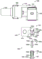
图18是图8的凸形端子组件的弹簧组件的透视图,示出了处于接合状态SJ的弹簧组件;18 is a perspective view of the spring assembly of the male terminal assembly of FIG. 8, showing the spring assembly in an engaged state S J ;
图19是图18的弹簧组件的底视图;Figure 19 is a bottom view of the spring assembly of Figure 18;
图20是沿图19的线20-20截取的弹簧组件的剖视图;Figure 20 is a cross-sectional view of the spring assembly taken along line 20-20 of Figure 19;
图21A是图18的弹簧座的透视图;Figure 21A is a perspective view of the spring seat of Figure 18;
图21B是图18的弹簧构件的透视图;Figure 21B is a perspective view of the spring member of Figure 18;
图22是带有电池组以及车轮和轮胎的车辆滑板底盘的透视图,该车辆滑板包括连接器系统的第一实施方案和第二实施方案两者;并且22 is a perspective view of a vehicle skateboard chassis with a battery pack and wheels and tires, the vehicle skateboard including both the first and second embodiments of the connector system; and
图23是具有图22的滑板底盘和电池组的机动车辆的透视图;23 is a perspective view of a motor vehicle having the skateboard chassis and battery pack of FIG. 22;
图24是示出连接器系统的部件的框图;Figure 24 is a block diagram illustrating components of a connector system;
图25A是示出凸形端子的部件的框图;FIG. 25A is a block diagram showing components of a male terminal;
图25B是示出凸形端子的侧壁部分的部件的框图;25B is a block diagram showing components of a sidewall portion of a male terminal;
图25C是示出凸形端子的接触臂的部件的框图;25C is a block diagram showing components of a contact arm of a male terminal;
图25D是示出凸形端子的接触臂开口的部件的框图;Figure 25D is a block diagram showing the components of the contact arm opening of the male terminal;
图26是示出弹簧座的部件的框图;Figure 26 is a block diagram illustrating components of a spring seat;
图27是示出凸形壳体组件的部件的框图;Figure 27 is a block diagram illustrating components of a male housing assembly;
图28是示出弹簧构件的部件的框图;Figure 28 is a block diagram illustrating components of a spring member;
图29是连接器系统的第二实施方案的透视图,该连接器系统包括凸形连接器组件和凹形连接器组件;Figure 29 is a perspective view of a second embodiment of a connector system comprising a male connector assembly and a female connector assembly;
图30是图29的连接器系统的侧视图;Figure 30 is a side view of the connector system of Figure 29;
图31是图29的连接器系统的分解图,示出了凸形连接器组件和凹形连接器组件;Figure 31 is an exploded view of the connector system of Figure 29, showing the male connector assembly and the female connector assembly;
图32是图29的连接器系统的顶视图;Figure 32 is a top view of the connector system of Figure 29;
图33是沿图32的线33-33截取的连接器系统的剖视图;Figure 33 is a cross-sectional view of the connector system taken along line 33-33 of Figure 32;
图34是图29的连接器系统的侧视图;并且Figure 34 is a side view of the connector system of Figure 29; and
图35是沿图34的线35-35截取的连接器系统的剖视图。35 is a cross-sectional view of the connector system taken along line 35-35 of FIG. 34 .
具体实施方式Detailed ways
在以下具体实施方式中,以举例的方式阐述了许多具体细节,以便提供对相关教导内容的透彻理解。然而,对于本领域的普通技术人员来说应该显而易见的是,可以在没有此类细节的情况下实践本教导内容。在其它情况下,为了避免不必要地模糊本教导内容的各方面,已经在相对较高的层次上描述了众所周知的方法、过程、部件和/或电路,而没有详细说明。In the following detailed description, numerous specific details are set forth by way of example in order to provide a thorough understanding of the relevant teachings. It should be apparent, however, to one of ordinary skill in the art that the present teachings may be practiced without such details. In other instances, well-known methods, procedures, components and/or circuits have been described at a relatively high level and have not been described in detail in order to avoid unnecessarily obscuring aspects of the present teachings.
虽然本公开包括许多不同形式的实施方案,但在附图中示出并将在本文详细地描述特定实施方案,同时理解本公开应被认为是所公开的方法和系统的原理的例证,并且不旨在将所公开概念的广泛方面限制为所示的实施方案。如将要实现的,所公开的方法和系统能够进行其它和不同的构造,并且能够在不脱离所公开的方法和系统的范围的情况下修改若干细节。例如,以下实施方案中的一个或多个实施方案(部分或全部)可以与所公开的方法和系统一致地结合。因此,附图和具体实施方式在本质上应被视为例示性的,而非进行约束或限制。While this disclosure includes embodiments in many different forms, certain embodiments are shown in the drawings and will be described in detail herein, with the understanding that this disclosure should be considered as illustrative of the principles of the disclosed method and system, and not as an illustration. It is intended that the broad aspects of the disclosed concepts be limited to the embodiments shown. As will be realized, the disclosed methods and systems are capable of other and different configurations, and their several details can be modified without departing from the scope of the disclosed methods and systems. For example, one or more (some or all) of the following embodiments may be incorporated in accordance with the disclosed methods and systems. Accordingly, the drawings and detailed description are to be regarded as illustrative in nature and not restrictive or restrictive.
附图示出了连接器系统100、4100的两个实施方案,该连接器系统被设计成将一个设备或部件以机械的方式和电的方式联接到配电系统或环境内的另一个设备或部件。例如,设备或组件可以是电流供应设备或组件(例如,诸如交流发电机或电池等的电源),并且另一设备或部件可以是电流消耗设备或部件(例如,散热器风扇、加热支座、配电部件或另外的电流消耗部件)。包括连接器系统100、4100的所述配电系统或环境可以安装在飞机、机动车辆、军用车辆(例如,坦克、运兵车、重型卡车和部队运输车)、公共汽车、机车、拖拉机、船、潜艇、电池组、24伏至48伏系统内,用于高功率应用、用于高电流应用、用于高电压应用。The figures show two embodiments of a
图28至图29中示出了连接器系统100、4100的示例性应用,其中连接器系统100、4100与安装在车辆滑板S中的电池组200结合使用,其中车辆滑板S安装在车辆V中。电池组200(见图22至图23)被构造为定位在车辆滑板S(见图22)内,电池组200和车辆滑板S两者均被构造为定位在机动车辆V(见图23)内。在该应用和其它应用中,配电部件对于满足配电系统和机动车辆的行业标准、生产和性能要求是必不可少的。应当理解,多个连接器系统100、4100可用于单个应用。针对连接器系统100、4100的其它实施方案、构造和用途在本专利申请内描述并且由本公开设想。An exemplary application of the
本文公开了连接器系统100的第一实施方案的各个方面。具体地,连接器系统100由以下构成:(i)凸形连接器组件1000,(ii)凹形连接器组件2000,以及(iii)部件头座3000。图1至图20示出了凸形连接器组件1000的各种视图和部件。凸形连接器组件1000主要由以下构成:(i)凸形壳体组件1100,(ii)具有凸形端子主体1472和内部弹簧组件1455的凸形端子组件1430,以及(iii)应变消除组件1800。图1至图2示出了凹形连接器组件2000和部件头座3000的各种视图和部件。凹形连接器组件2000主要由凹形端子组件2430构成,而部件头座3000主要由凹形壳体组件3100构成。Various aspects of a first embodiment of the
本文公开了连接器系统4100的第一实施方案的各个方面。具体地,连接器系统4100由以下构成:(i)凸形连接器组件5000,以及(ii)凹形连接器组件6000。图29至图35示出了凸形连接器组件5000的各种视图和部件。凸形连接器组件5000主要由以下构成:(i)凸形壳体组件5100,(ii)凸形端子组件5430,以及(iii)应变消除组件5800。图29至图35示出了凹形连接器组件6000的各种视图和部件。凹形连接器组件6000主要由以下构成:(i)凹形壳体组件6100,以及(ii)凹形端子组件6430。Various aspects of a first embodiment of a
第一实施方案first embodiment
1)凸形连接器组件1) Male connector assembly
凸形连接器组件1000包括多个部件,这些部件被设计成定位在部件或设备的外部(例如,散热器风扇、加热支座、配电部件或另外的电流消耗部件)。凸形连接器组件1000主要有以下构成:(i)凸形壳体组件1100,(ii)凸形端子组件1430,以及(iii)应变消除组件1800。
凸形壳体组件1100封装或围绕容纳在凸形连接器组件1000内的其它部件的大范围。凸形壳体组件1100大体包括:(i)凸形壳体1104和(ii)连接器位置保证(“CPA”)1170。凸形壳体1104包括两个壁布置,其中:(i)第一侧壁布置1106具有管状构造并且被设计成接纳导线1530的范围,并且(ii)第二侧壁布置1108具有管状构造并且被设计成接纳凸形端子组件1430的大范围。侧壁的第一布置1106包括凸形壳体联接装置1110,该凸形壳体联接装置被设计成与下文将讨论的外盖1810相互作用,并且是应变消除组件1800的一部分。壁的第二布置1108包括CPA接纳器1160,该CPA接纳器从侧壁1104a、1108a延伸,并且被设计成接纳CPA 1170的范围。两个壁布置通常是由绝缘材料形成的,该绝缘材料被设计成使流动穿过凸形连接器组件1000的电流与其它部件隔离。所述CPA 1170大体被设计成使连接器系统100能够满足USCAR规范,包括USCAR-12、USCAR-25和USCAR-2。关于凸形壳体组件1100(包括CPA 1170)的附加细节在PCT/US2019/36070和PCT/US20/49870中有所描述,这两篇专利均通过引用并入本文。
在其它实施方案中,壳体组件1100可以以允许从任何方向配合的方式设计。换句话讲,凸形连接器组件1000不是以仅当凸形连接器组件1000在特定取向时才允许连接器组件1000与凹形端子2430配合的方式键控。在该另选的构造中,CPA 1170可以被省略或者可以具有不同的结构构造以允许部件之间的这种类型的配合。另外,壳体组件1100可以被加罩,可以具有非导电材料和/或导电材料的附加层,和/或可以具有较大的器件封装以便接纳多个凸形端子组件1430。In other embodiments,
图2、图5、图7至图20提供了凸形端子组件1430的各种视图。具体地参考第一实施方案,凸形端子组件1430包括弹簧构件1440a和凸形端子1470。凸形端子1470包括凸形端子主体1472和凸形端子连接构件或板1474。所述凸形端子主体1472包括凸形端子侧壁布置1482,该凸形端子侧壁布置被构造为提供弹簧接纳器1486,该弹簧接纳器被设计成接纳内部弹簧构件或凸形弹簧构件1440a。参考图7、图9、图13、图15、图17和图18至图20,内部弹簧组件或弹簧组件1455包括内部弹簧座或弹簧座1456以及内部弹簧构件或弹簧构件1440a。弹簧座1456被构造为:(i)接纳并保持弹簧构件1440a的范围,(ii)在接合状态SJ下将弹簧构件1440a固定在凸形端子主体1472内,(iii)帮助确保弹簧构件1440a在凸形端子主体1472内正确定位、对准和/或居中。Various views of the
参考图7、图9、图13、图15、图17和图18至图20,弹簧座1456由第一部分或头部部分1457以及第二部分或主体部分1460构成。头部部分1457包括:(i)第一或外部部分1457a,其被构造为定位在凸形端子主体1472之外或外部,(ii)第二或内部部分1457b,其被构造为定位在凸形端子主体1472之内或内部,以及(iii)对准机构或防差错1459。首先关注外部部分1457a,所述外部部分1457a的直径DESH大于凸形端子主体1472的内径DIMB,而外部部分1457a的直径DESH约等于凸形端子主体1472的外径DOMB。外部部分1457a的直径DESH:(i)防止座1456由于外部部分1457a和凸形端子主体1472的前部范围之间的相互作用而被插入到凸形端子主体1472中过深,并且(ii)帮助防止外物与凸形端子1430进行接触,因为该外部部分定位在凸形端子主体1472的前面。另外,应当理解,外部部分1457a的直径DESH优选地不大于凸形端子主体1472的外径DOMB,因为较大的直径DESH将可能阻止凸形端子组件1430和凹形端子组件2430之间的正确配合。Referring to FIGS. 7 , 9 , 13 , 15 , 17 and 18-20 , the
现在关注弹簧座1456的内部部分1457b,所述内部部分1457a的直径DISH小于或基本上等于凸形端子主体1472的内径DIMB。内部部分1457b的该较小直径DISH使座1456能够插入凸形端子主体1472内。另外,内部部分1457b的直径DISH大于座1456的主体部分1460的直径DBSH。该较大的直径允许座1456的范围紧密地适配在端子1430内,同时利用较小的直径来帮助确保座1456在连接器系统100的操作期间不干扰弹簧1440a的运动。应当理解,本公开也设想了座1456的其它直径和构造。Focusing now on the
外部部分1457a和内部部分1457b的构造以及它们的相关联直径DESH、DISH形成凹陷部1458,该凹陷部被构造为当座1456在完全联接状态下被联接到凸形端子主体1472时接纳凸形端子主体的范围。定位在所述凹陷部1458内的是对准机构1459。对准机构1459被设计成确保座1456正确定位在凸形端子主体1472内,由此座1456的正确定位确保弹簧构件1440a正确定位在凸形端子主体1472中。相比于不具有正确对准的弹簧构件的端子,将弹簧构件1440a正确对准在凸形端子主体1472内提供了许多优点,其中此类优点包括:(i)确保弹簧构件1440a对凸形端子主体1472施加正确的偏置力以提供凸形端子组件1430与凹形端子组件2430之间的正确连接,(ii)帮助改善端子组件1430、2430的耐久性和可使用寿命,以及(iii)本文所公开的或可由本领域普通技术人员从本公开推断出的其它有益特征。The configuration of
在该实施方案中,对准机构1459是防旋转突起部1459a,该防旋转突起部被构造为由形成在凸形端子主体1472的前部范围中的插座1476接纳。防旋转突起部1459a通过限制弹簧构件1440a能够在凸形端子主体1472内旋转或误定位的量来帮助使弹簧构件1440a对准或居中。应当理解,在其它实施方案中,对准机构1459可以采取其它形式,诸如:(i)从凸形端子主体1472的范围向内延伸的突起部,(ii)从弹簧构件1440a向外延伸并且由凸形端子主体1472中的凹陷部、棘爪或开口接纳的突起部,(iii)从接触臂1494a至1494d朝向连接器的中心向内延伸的突起部,(iv)被设计成帮助确保弹簧构件1440a对准在凸形端子主体1472内并且不能在弹簧接纳器1486内旋转的其它结构的突起部、突片、凹槽、凹陷部或范围。In this embodiment, the
应当进一步理解,代替利用基于机械的对准机构1459,对准机构1459可以是基于力的,其中可以利用的此类力是磁力或化学力。在该示例中,座1456可以焊接到凸形端子主体1472。与基于机械或力的对准机构1459相比,对准机构1459可以是形成凸形端子组件1430的方法或过程。例如,对准机构1459可以不是结构,而是可以以不需要组装的方式将弹簧构件1440a同时印刷在凸形端子主体1472内。换句话讲,对准机构1459可以采取许多形式(例如,基于机械、基于力或基于过程)以实现将弹簧构件1440a对准在凸形端子主体1472内的目的。It should be further understood that instead of utilizing a mechanically based
第二部分或主体部分1460从第一或头部部分1456的内部部分1457b延伸并且与其一体形成。主体部分1460包括有助于弹簧构件1440a的定位和保持的多个特征(例如,孔、构件和结构)。特别地,主体1460包括形成定位结构1462a至1462d的弹簧孔1461a至1461d。当弹簧构件1440a定位在弹簧座1455内以形成接合状态SJ时,所述弹簧孔1461a至1461d被设计成接纳弹簧臂1494a至1494d的至少一范围并且优选地接纳整个弹簧臂1494a至1494d。这样,弹簧孔1461a至1461d具有足以接纳弹簧臂1494a至1494d的至少一范围并且优选地接纳整个弹簧臂1494a至1494d的长度和宽度。换句话讲,弹簧孔1461a至1461d的长度和宽度优选地大于弹簧臂1494a至1494d的长度和宽度。A second or
弹簧孔1461a至1461d具有第一或前部部分1463a至1463d和第二或后部部分1464a至1464d。前部部分1463a至1463d具有第一宽度并且从座1456的头部部分1457向后延伸,并且同时第二部分1464a至1464d具有第二宽度并且从第一部分1463a至1463d向后延伸至下列中的任一者:(i)座1456的后部端部1456b或(ii)保持装置1465。与第一部分1463a至1463d相关联的第一宽度大于与第二部分1464a至1464d相关联的第二宽度。换句话讲,被定位成相邻于第一部分1464a至1464d的定位结构1462a至1462d的范围小于被定位成相邻于第二部分1463a至1463d的定位结构1462a至1462d的范围。弹簧孔1461a至1461d的该放大的范围或定位结构1462a至1462d的减小的范围帮助确保座1456在连接器系统100的插入和操作期间不干扰弹簧构件1440a的全向收缩/膨胀。应当理解,在其它实施方案中,弹簧孔1461a至1461d的宽度变化可以被省略、反转,或者第一部分与第二部分之间的差异可以被增大或减小。The spring holes 1461a-1461d have a first or front portion 1463a-1463d and a second or
定位结构1462a至1462d被设计成将弹簧构件1440a对准、定位并保持在凸形端子主体1472内。定位结构1462a至1462d沿弹簧臂1494a至1494d的至少一范围延伸并且优选地沿弹簧臂1494a至1494d的整个长度延伸。定位结构1462a至1462d具有基本上三角形的横截面形状,其中该三角形形状的最外侧范围是曲线的。换句话讲,定位结构1462a至1462d具有两个直线侧面以及连接这两个直线侧面的一个曲线侧面。如上所述,由弹簧孔1461a至1461d形成的定位结构1462a至1462d具有:(i)沿弹簧孔1461a至1461d的第一部分1463a至1463d延伸的第一范围1465a至1465d,以及(ii)沿弹簧孔1461a至1461d的第二部分1464a至1464d延伸的第二范围1466a至1466d。第一范围1465a至1465d具有第一横截面积和第一深度(从外表面朝向座1456的中心延伸),同时第二范围1466a至1466d具有第二横截面积和第二深度。第一横截面积和第一深度两者均小于第二横截面积和第二深度。应当理解,在其它实施方案中,定位结构1462a至1462d的横截面积和深度变化可以保持恒定、具有较大的变化幅度或具有较小的变化幅度。还应当理解,定位结构1462a至1462d的横截面形状可以与图中所示的不同,并且/或者可以在定位结构1462a至1462d之间变化。Locating features 1462a - 1462d are designed to align, position and retain
保持装置1465被设计和构造为将弹簧构件1440a保持在座1456内。在附图中所示的实施方案中,所述保持装置1465是在定位结构1462a至1462d之间延伸的横梁1467a至1467b。特别地,横梁1467a定位在座1456的后部端部1456b附近并且在定位结构1462a至1462b之间延伸,并且横梁1467b定位在座1456的后部端部1456b附近并且在定位结构1462c至1462d之间延伸。横梁1467a至1467b的最后表面是倾斜的,以有助于座1456和弹簧构件1440a的联接。具体地,这些倾斜的壁1468a至1468b帮助使弹簧构件1440a居中并且迫使第一对定位结构1462a至1462b远离第二对定位结构1462c至1462d。这样,使用者或组装者必须简单地对弹簧构件1440a施加向前指向的力以便使定位结构1462a至1462d暂时变形,从而允许弹簧构件1440a的插入。一旦弹簧构件1440a定位在保持器1456中,定位结构1462a至1462d就可以返回到正常或未变形位置。在该未变形位置,横梁1467a至1467b定位在弹簧构件1440a的后方以将弹簧构件1440a保持在座1456内。应当理解,将弹簧构件1440a与座1456解联接需要使用者或安装者沿相反方向施加力,以便使成对的定位结构1462a至1462d进一步变形到足以允许将弹簧构件1440a从座1456抽出。应当理解,横梁没有跨定位结构1462a至1462d中的每个定位结构(例如,在1462b和1462c之间)联接,因为使定位结构1462a至1462d变形到必要程度即便不是不可能,也可能很困难。
应当理解,在其它实施方案中,保持装置1465可以采取其它形式,诸如:(i)锁定后壁,(ii)从弹簧构件1440a延伸并由座1456接纳的突起部,(iii)弹簧构件1440a中的开口,该开口接纳座1456的范围,或者(iv)将一个结构保持/联接到另一个结构的任一其它方式,该方式可包括使用突起部、突片、凹槽、凹陷部或范围。应当进一步理解,代替利用基于机械的保持装置1465,保持装置1465可以是基于力的,其中可以利用的此类力是磁力或化学力。在该示例中,座1456可以焊接到凸形端子主体1472。与基于机械或力的保持装置1465相比,保持装置1465可以是形成凸形端子组件1430的方法或过程。例如,保持装置1465可以不是结构,而是可以以不需要组装的方式将弹簧构件1440a同时印刷在座1456内。换句话讲,保持装置1465可以采取许多形式(例如,基于机械、基于力或基于过程)以实现将弹簧构件1440a固定到座1456的目的。It should be appreciated that in other embodiments, retaining means 1465 may take other forms, such as: (i) a locking rear wall, (ii) a protrusion extending from
弹簧构件1440a包括弹簧构件侧壁1442a至1442d和后部弹簧壁1444的布置。每个弹簧构件侧壁1442a至1442d由以下构成:(i)第一或曲线弹簧区段1448a至1448d,以及(iii)第二区段或弹簧臂1452a至1452d。曲线弹簧区段1448a至1448d在后部弹簧壁1444与弹簧臂1452a至1452d之间延伸,并且将弹簧臂1452a至1452d定位成基本上垂直于后部弹簧壁1444。换句话讲,弹簧臂1452a至1452d的外表面基本上垂直于后部弹簧壁1444的外表面。The
如图21B所示,弹簧臂1452a至1452d从弹簧构件1440a的第一或曲线弹簧区段1448a至1448d延伸,远离后部弹簧壁1444,并且在自由端1446处终止。弹簧臂1452a至1452d没有连接至彼此,并且因此在弹簧构件1440a的弹簧臂1452a至1452d之间形成弹簧臂间隙1450a至1450d。弹簧臂间隙1450a至1450d有助于弹簧臂1452a至1452d的全向膨胀,这有利于凸形端子1470与凹形端子组件2430之间的机械联接。As shown in FIG. 21B ,
弹簧臂1452a至1452d大体为平面,并且定位成使得弹簧臂1452a至1452d的外表面基本上垂直于后壁1444的外表面。与在PCT/US2018/019787的图4至图8内公开的弹簧臂31不同,弹簧臂1452a至1452d的自由端1446不具有曲线部件。相反,弹簧臂1452a至1452d具有基本上平的外表面。该构造是有益的,因为它确保与弹簧1440a相关联的力基本上垂直于凸形端子主体1472的自由端1488而施加。相比之下,在PCT/US2018/019787的图4至图8内公开的弹簧臂31的曲线部件不这样施加力。The
内部弹簧构件1440a通常由单个材料件(例如,金属)形成;因此,弹簧构件1440a是一体式弹簧构件1440a或具有一体形成的特征部。特别地,以下特征部一体形成:(i)曲线弹簧区段1448a至1448d,以及(ii)弹簧臂1452a至1452d。为了一体形成这些特征部,通常使用模具成形工艺来形成弹簧构件1440a。模具成形工艺机械地迫使弹簧构件1440a成形。如在下文和在PCT/US2019/036010中更详细地讨论,当弹簧构件1440a由扁平金属片形成,安装在凸形端子1472内并且连接到凹形插座2472,并且经受升高的温度时,部分地由于弹簧构件1440a尝试返回到扁平片的事实,弹簧构件1440a在接触臂1494a至1494d上施加向外指向的弹簧热力STF。然而,应当理解,可以使用其它类型的形成弹簧构件1440a的方法,诸如铸造或使用增材制造工艺(例如,3D打印)。在其它实施方案中,弹簧构件1440a的特征部可以不由一体件形成或不被一体形成,而是由焊接在一起的单独的件形成。The
在未示出的另选实施方案中,弹簧构件1440a可以包括凹陷部和相关联的加强肋。如PCT/US2019/036010中所讨论,弹簧构件1440a的构造的这些变化改变了与弹簧1440a相关联的力。特别地,弹簧偏置力SBF是当凸形端子组件1430被插入凹形端子组件2430内时由弹簧构件1440a施加以抵抗弹簧构件1440a的自由端1446的向内偏转的力的量。具体地,由于凸形端子主体1472的外表面的范围略大于凹形插座2472的内侧的事实,在插入凸形端子组件1430期间发生这种向内偏转。因此,当凸形端子组件1430被插入到凹形端子组件2430中时,外表面的范围被迫使朝向凸形端子1470的中心1490。对外表面的这种向内的力使弹簧构件1440a的自由端1446向内移位(即,朝向中心1490)。弹簧构件1440a通过提供弹簧偏置力SF来抵抗该向内移位。在其它实施方案中,弹簧臂1452a至1452d可以被联接到其它结构以限制它们的全向膨胀。单个弹簧臂1452a至1452d和开口的数量和宽度可能有所不同。另外,单个弹簧臂1452a至1452d的宽度通常彼此相等;然而,在其它实施方案中,弹簧臂1452a至1452d中的一个弹簧臂可以比其它弹簧臂宽。In an alternative embodiment not shown, the
图8至图17示出了包括凸形端子主体1472和凸形端子连接板1474的凸形端子1470。具体地,凸形端子连接板1474被联接到凸形端子主体1472并且被构造为接纳将凸形端子组件1430连接到连接器系统100之外的设备(例如,交流发电机)的结构(例如,引线或导线)的范围。导线1530通常被焊接到连接板1474,然而,本公开设想将导线1530连接到连接板1474的其它方法(例如,将导线1530形成为连接板1474的一部分)。例如,可以利用压接连接来代替所公开的焊接工艺。8 to 17 illustrate a male terminal 1470 including a male
如图8至图17所示,端子侧壁布置1482为端子主体1472提供了大体柱形端子构造。凸形端子侧壁1482包括:(i)侧壁部分1492a至1492d,(ii)接触臂1494a至1494d,以及(iii)多个接触臂开口1510a至1510d。如图9至图17最佳所示,侧壁部分1492a至1492d基本上是曲线的并且包括四个区段1498、1500、1502和1504。特别地,这四个区段是:(i)第一或端部区段1498a至1498d,(ii)第二、后部或中间区段1500a至1500d,(iii)第三或相对端部区段1502a至1502d,以及(iv)第四或前部区段1504a至1504d。第二、后部或中间区段1500a至1500d和第四或前部区段1504a至1504d两者被联接:(i)第一或端部区段1498a至1498d和(ii)第三或相对端部区段1502a至1502d。应当理解,本公开设想了包括更多或更少的区段和/或侧壁部分1492a至1492d的其它构造。As shown in FIGS. 8-17 , terminal sidewall arrangement 1482 provides
接触臂开口1510a至1510d与侧壁部分1492a至1492d一体形成,继而侧壁部分又勾划接触臂1494a至1494d和侧壁部分1492a至1492d的四个区段1498、1500、1502、1504的轮廓。换句话讲,接触臂开口1510a至1510d围绕接触臂1494a至1494d的三个侧面,以便形成允许接触臂1494a至1494d不被侧向连接到以下的构造:(i)另一个接触臂1494a至1494d或(ii)除接触臂1494a至1494d所联接到的第二、后部或中间区段1500a至1500d之外的结构。如图10、图11和图17最佳所示,接触臂开口1510a至1510d包括沿接触臂1494a至1494d的每个伸长边缘延伸的侧向范围1512a至1512h。例如,一个接触臂开口1510a包括:(i)定位在接触臂1494a和侧壁部分1492a的第一区段1498a之间的第一侧向范围1512a,以及(ii)定位在接触臂1494a和侧壁部分1492a的第三区段1502a之间的第二侧向范围1512b。特别地,第一侧向范围1512a在接触臂1510a的第一侧向边缘1524a和接触臂开口1510的第一内部边缘1518a之间延伸,并且第二侧向范围1512b在接触臂1510a的第二侧向边缘1524b和接触臂开口1510的第二内部边缘1518b之间延伸。
按照上述构造,沿接触臂1494a至1494d延伸的、接触臂开口1510a至1510d的所述侧向范围1512a至1512h不具有一致的宽度。这样,所述侧向范围1512a至1512h由以下构成:(i)第一部分1514a至1514h,其具有第一侧向宽度WL1,并且被定位成相邻于侧壁部分1492a至1492d的中间区段1500a至1500d,以及(ii)第二部分1516a至1516h,其具有第二侧向宽度WL2,并且被定位成使得该第二部分邻接第一部分1514a至1514h并且在侧壁部分1492a至1492d的前部区段1504a至1504d处终止。与第一部分1514a至1514h相关联的第一宽度不同于与第二部分1516a至1516h相关联的第二宽度。特别地,在附图中所显示的实施方案中,第一侧向宽度WL1大于第二侧向宽度WL2。例如,在所显示的实施方案中,第一宽度为约0.95mm,而第二宽度为约0.45mm。对于这些变化宽度,应当理解,接触臂1510a的第一侧向边缘1524a和第二侧向边缘1524b不是基本线性的。另外,当凸形端子组件1430处于完全联接状态SFC时,接触臂开口1510a至1510d的范围与弹簧臂间隙1450a至1450d对准。这种构造形成四个弹簧臂1452a至1452d和四个接触臂1494a至1494d。应当理解,在其它实施方案中,弹簧臂1452a至1452d的数量可以与接触臂1494a至1494d的数量不匹配。例如,可以存在较少的弹簧臂1452a至1452d。With the above configuration, the
如图10至图11和图15最佳所示,接触臂1494a至1494d如下延伸:(i)从侧壁部分1492a至1492d的中间区段1500a至1500d的范围延伸,(ii)跨过接触臂开口1510a至1510d的范围延伸,以及(iii)刚好在接近第四或前部区段1504a至1504d处终止。相比于在PCT/US2018/019787中图9至图15、图18、图21至图31、图32、图41至图42、图45至图46、图48和图50所示的端子的构造,这种构造是有益的,因为该构造允许:(i)总体长度可更短,这意味着形成所需的金属材料更少并且凸形端子1470可安装在更窄的限制性空间中;(ii)具有更高载流能力;(iii)更易于组装;(iv)改进的结构刚度,因为接触臂1494a至1494d定位在第一凸形端子侧壁部分1492a至1492d的内部;(iv)结合PCT/US2019/036010所公开的益处;以及(v)本文公开的或可由本领域普通技术人员根据本公开推断的其它有益特征。As best shown in FIGS. 10-11 and 15, the
如图15和图17最佳所示,接触臂1494a至1494d包括:(i)从第二、后部或中间区段1500a至1500d延伸的第一或后部范围1495a至1495d,(ii)在第一范围1495a至1495d和第三范围1497a至1497d之间延伸的第二或中部范围1496a至1496d,以及(iii)在第二范围1496a至1496d和自由端1488之间延伸的第三或曲线范围1497a至1497d。所述范围1495a至1495d、1496a至1496d和1497a至1497d具有不一致的宽度,其中所述宽度包括:(i)第一或后部范围1495a至1495d具有第一接触臂宽度WC1,该第一接触臂宽度在接触臂开口1510a至1510d的侧向范围1512a至1512h的第一部分1514a至1514h之间延伸,以及(ii)第二范围1496a至1496d和第三范围1497a至1497d具有第二接触臂宽度WC2,该第二接触臂宽度在接触臂开口1510a至1510d的侧向范围1512a至1512h的第二部分1516a至1516h之间延伸。如上所述,部分1514a至1514h、1516a至1516h的宽度有差别并且因此接触臂1494a至1494d的宽度有差别。As best shown in FIGS. 15 and 17 , the
在该实施方案中,从第一侧向边缘1524a延伸到第二侧向边缘1524b并且与接触臂1494a至1494d的第一范围1495a至1495d相关联的第一接触臂宽度WC1小于从第一侧向边缘1524a延伸到第二侧向边缘1524b并且与接触臂1494a至1494d的第二范围1496a至1496d和第三范围1497a至1497d相关联的第二接触臂宽度WC2。第一范围1495a至1495d的宽度的这种减小形成具有不规则外周边的接触臂1494a至1494d,其中第一凹口1520a至1520d和相对的第二凹口1522a至1522d形成在接触臂1494a至1494d中并且沿接触臂1494a至1494d的第一范围1495a至1494d的长度延伸。在一个实施方案中,第一宽度为约1.9mm,而第二宽度为约2.9mm。因此,每个凹口1520a至1520d、1522a至1522d具有约0.5mm的宽度。应当理解,在其它实施方案中:(i)曲线范围1497a至1497d的宽度可以不等于中部范围1496a至1496d的宽度,(ii)范围1495a至1495d、1496a至1496d、1497a至1497d的宽度波动可以更大或更小,(iii)可以存在具有附加不同宽度的附加范围(例如,10个范围,其中每个范围具有不同的宽度),(iv)对于每个接触臂1494a至1494d,凹口1520a至1520d、1522a至1522d的数量、深度或构造可以不相等,(v)范围中的每个范围的宽度可以基本上相等。In this embodiment, the first contact arm width W C1 extending from the first
接触臂1494a至1494d的较小的第一宽度,即接触臂1494a至1494d的后部范围1495a至1495d减小了当将凸形端子组件1430联接到凹形端子组件2430时使接触臂1494a至1494d向内且朝向凸形端子1470的中心1490偏转或移位所需的力。这是有益的,因为它减小了与凸形端子主体1472相关联的插入力并且增大了与内部弹簧构件1440a相关联的插入力以便维持相同的组合插入力水平。换句话讲,所公开的连接器系统100应用与包括具有直线边缘的接触臂的类似连接器系统相关联的相同的插入力要求。然而,与有助于插入力的部件相关联的力已经被重新分配,以对弹簧构件1440a施加更大的依赖,而对凸形端子主体1472施加更小的依赖。这种对内部弹簧构件1440a的更大的依赖是有益的,因为设计者可以在不需要改变端子主体1472的情况下容易地改变连接器系统的特性。例如,设计者可以将更硬的弹簧构件1440a插入弹簧接纳器1486内,以便增加系统100的电流容量。或者如果存在规定目标插入力的特定客户要求,设计者可以简单地选择满足这些要求的弹簧构件1440a,而不需要重新设计凸形端子主体1472。连接器系统100的这种模块性和灵活性是对现有技术的显著改进,因为减少了产品库存单位的数量,增强了在不用重新装备或重新设计连接器的情况下满足客户要求的能力,并且/或者限制了利用新的/不同的连接器所需的测试和其它步骤。由于这些原因以及基于本公开内容对本领域技术人员显而易见的附加原因,连接器系统100并且具体地凸形端子组件1430,提供了优于PCT/US19/36010中所示和公开的凸形端子组件430的显著优点。The smaller first width of the
接触臂1494a至1494d以向外的角度远离第二、后部或中间区段1500a至1500d的向前范围而延伸。特别地,向外角度α,其在凸形端子侧壁1492a至1492d的范围的外表面和接触臂1494a至1494d的第一范围的外表面之间可以介于179.9度和172度之间,优选地介于6度和12度之间并且最优选地介于8度和10度之间。这种向外角度在多个附图中示出,但是结合图15可以最佳地显现。当凸形端子组件1430被插入到凹形端子组件2430中时,这种构造允许接触臂1494a至1494d被凹形插座2472向内并朝向凸形端子1470的中心1490偏转或移位。该向内偏转在图25中最佳示出。该向内偏转通过确保接触臂1494a至1494d被放置成与凹形插座2472接触来帮助确保正确的机械和电气连接。The
如图10至图11和图15所示,接触臂1494a至1494d的末端被定位成:(i)在接触臂开口1510a至1510d内,(ii)基本上平行于凸形端子侧壁1492a至1492d,并且(iii)在弹簧构件1440a被插入到弹簧接纳器1486中时,接触弹簧臂1452a至1452d的平的外表面。这种构造相比于PCT/US2018/019787中图3至图8所示的构造是有益的,因为凸形端子组件1430的组装者不必施加很大的力来使接触臂1494a至1494d的大部分向外变形以接纳弹簧构件1440a。由于接触臂11的倾斜以及弹簧臂31的外表面与接触臂11的内表面相邻于彼此而在它们之间没有形成间隙的事实,这种所需的变形可以在PCT/US2018/019787的图6中最佳示出。与PCT/US2018/019787中的图3至图8相比,本申请的图7示出了在弹簧构件1440a的外表面与接触臂1494a至1494d的内表面之间形成的非常小的间隙。因此,由于组装者不必在弹簧1440a的插入期间迫使接触臂1494a至1494d显著变形的事实,所以需要非常小的力来将弹簧构件1440a插入到弹簧接纳器1486中。As shown in FIGS. 10-11 and 15, the ends of the
凸形端子1470通常由单个材料件(例如,金属)形成;因此,凸形端子1470是一体式凸形端子1470并且具有一体形成的特征部。为了一体形成这些特征部,通常使用模切工艺来形成凸形端子1470。然而,应当理解,可以利用其它类型的形成凸形端子1470的方法,诸如铸造或使用增材制造工艺(例如,3D打印)。在其它实施方案中,凸形端子1470的特征部可以不由一体件形成或不被一体形成,而是由焊接在一起的单独的件形成。在形成凸形端子1470时,应当理解,可以在凸形端子1470内形成任意数量(例如,介于1和100之间)的接触臂1494a至1494d。Male terminal 1470 is typically formed from a single piece of material (eg, metal); thus,
将内部弹簧构件1440a定位在凸形端子组件1430内跨越多个步骤或阶段发生。图7提供了处于未接合状态SUJ的弹簧组件1455的第一实施方案,而图18至图20示出了处于接合状态SJ的弹簧组件的第一实施方案。如上所述,为了将弹簧组件1455从未接合状态SUJ移动到接合状态SJ,使用者或组装者将弹簧构件1440a,即弹簧臂1452a至1452d,与弹簧座1456的弹簧臂孔1461a至1461d对准。在这些部件对准之后,使用者对这些部件施加压缩力,以便使定位结构1462a至1462d暂时弹性变形,从而允许弹簧构件1440a克服保持装置1465。一旦弹簧构件1440a被定位在座1456内,定位结构1462a至1462d就将返回到它们的未变形/初始状态,由此经由保持装置1465将弹簧构件1440a固定在座1456内。Positioning
然后将接合的SJ弹簧组件1455插入凸形端子主体1472内。这通过将主体部分1460定位在凸形端子主体1472的弹簧接纳器1486内并且施加将这两个部件压入彼此中的插入力FI来实现。当使用者或组装者施加该插入力FI时,使用者或组装者必须将对准机构1459与对准插座1476对准,以便将凸形端子组件从未联接状态SUC移动到完全联接状态FC。为了使对准机构1459与对准插座1476对准,组装者可能必须在凸形端子主体1472内扭转弹簧组件1455。一旦外部部分1457a的后部范围被定位成相邻于凸形端子主体1472的端部,凸形端子组件1430就处于完全联接状态FC。The engaged SJ
应变消除组件1800包括多个部件,诸如应变消除帽1810,这些部件被设计成消除对凸形端子组件1430和导线1530之间的连接施加的应变。关于该应变消除组件的附加细节结合PCT/US2019/36070公开,该专利内容通过引用完全并入本文。
2)凹形连接器组件2) Female connector assembly
凹形连接器组件2000主要由凹形端子组件2430构成。凹形端子组件2430包括侧壁布置2434,该侧壁布置形成凹形插座2472,该凹形插座被设计成接纳凸形端子组件1430的范围,以便将联接到凸形连接器组件1000的设备以电的方式和机械的方式连接到联接到部件头座3000的设备。凹形插座2472的横截面形状是基本上圆形的,并且其直径为约10.3mm。这样,该直径比凸形端子组件1430的外径(在接触臂1494a至1494d的最宽范围处测量,为约10.8mm)小约5%。如在PCT/US2019/36070、PCT/US2019/36010中所讨论,当凸形端子组件1430被插入到凹形端子组件2430中时,这种位置关系压缩弹簧构件1440a,以确保凸形端子组件1430与凹形端子组件2430进行正确的电气和机械连接。关于凹形端子组件2430的附加细节在PCT申请号PCT/US2019/36127、PCT/US2019/36070、PCT/US2019/36010中进行了一般性讨论,并且因此这些细节将不在此重复。然而,大体上凹形端子组件2430可以由导电材料(例如,铜)制成,并且可以被冲压、压制、拉制、模制、铸造、印刷,或者可以利用类似的制造方法。Female connector assembly 2000 is primarily composed of female terminal assemblies 2430 . The female terminal assembly 2430 includes a side wall arrangement 2434 that forms a female receptacle 2472 designed to receive the confines of the
3)部件头座3) Component header
部件头座3000主要由凹形壳体组件构成,该凹形壳体组件被设计成保护凹形端子组件2430并使其与外部结构隔离。为了实现这一点,中间壳体组件2100在由壁2160形成的接纳器内接纳凹形端子组件2430。所述壁2160包括斜面的或倾斜的壁布置2162,该壁布置从壳体2100的前部边缘向后延伸并且被设计成在凸形端子组件1430和凹形端子组件2430的配合期间压缩端子组件1430的接触臂1494。这些斜面的或倾斜的壁布置2162的构造和设计在PCT/US2019/36070中进行了详细描述,该专利被并入本文。这些斜面的或倾斜的壁2162具有后部边缘,该后部边缘被构造为当凹形端子组件2430被正确定位在部件头座3000内时邻接凹形端子组件2430的前部边缘。
4)连接连接器系统4) Connect the connector system
图1至图2示出了高功率连接器系统100如何能够从断开状态SDCON移动到完全连接状态SFCON。然后,高功率连接器系统100可以从该断开状态SDCON移动到部分连接状态,其中凸形连接器组件1000的接触臂1494a至1494d将要与凹形连接器组件2000的斜面的或倾斜的表面2162接触。该斜面的或倾斜的表面2162轻轻地且平稳地压缩接触臂1494a至1494p,直到它们能够容易地滑入并接触凹形插座2472的内表面。该过程更详细地描述于PCT/US2019/36070中,并且被并入本文。一旦凸形连接器组件1000完全连接到凹形连接器组件2000,高功率连接器系统100已经从部分连接状态SPCON移动到完全连接状态SFCON。最后,对CPA 1170施加力,该力致使CPA与部件头座3000的范围相互作用。一旦这种情况发生,凸形连接器组件1000就被锁定到凹形连接器组件2000。最后,安装者可以扫描透过壳体内的开口可见的CPA 1170的范围,如PCT/US20/49870中所述。1-2 illustrate how the high
第二实施方案second embodiment
如图29至图35所示,连接器系统4100的第二实施方案包括多个部件,这些部件被设计成将一个设备或部件以电的方式和机械的方式连接到配电环境内的另一个设备或部件。连接器系统4100的第二实施方案主要由以下构成:(i)凸形连接器组件5000和(ii)凹形连接器组件6000。凸形连接器组件5000包括:(i)壳体组件5100;(ii)凸形端子组件5430,该凸形端子组件包括凸形端子5470、内部弹簧组件5455,该内部弹簧组件包括弹簧座5456和弹簧构件5440a;(iii)凸形联锁组件5600;(iv)应变消除组件5800;以及(v)导线5495。凹形连接器组件6000包括:(i)壳体组件6100,以及(ii)凹形端子组件6430,该凹形端子组件包括具有凹形插座6472的凹形端子主体6434。连接器系统100、4100的第一实施方案和第二实施方案之间的唯一区别在于以下的构造:(i)壳体1100、5100、3000、6100,以及(ii)凸形端子连接板1474、5474。此外,端子组件1430、2430、5430、6430在实施方案100、4100中是相同的。As shown in FIGS. 29-35 , a second embodiment of a
鉴于这些实施方案之间的实质重叠,应当理解,为了简洁起见,可从说明书中省略图中所示的参考标号,因为类似结构具有类似标号。例如,与弹簧构件1440a相关的公开在本文不再重复,但其适用于弹簧构件5440a,如同该公开在本文重复。换句话讲,从该结构的功能性的说明或具体公开中省略参考标号不应当限制本专利申请的公开。相反,应参考可在本专利申请的另一部分或通过引用并入本文的其它专利申请内讨论的类似结构的公开。In view of the substantial overlap between these embodiments, it should be understood that, for the sake of brevity, reference numerals shown in the figures may be omitted from the description, as similar structures bear like numerals. For example, the disclosure related to
5) 端子特性和功能性5) Terminal characteristics and functionality
图33至图34描绘了在完全连接状态SFC下联接到凹形连接器组件6000的凸形连接器组件5000的横截面。虽然下文公开的内容是结合系统4100的所述第二实施方案讨论的,但是应当理解,该公开内容同样适用于系统100的第一实施方案。如图33最佳所示,弹簧臂5452a至5452d的一个或多个外表面与相应接触臂5494a至5494d的自由端5488接触。如上文所讨论,接触臂5494a至5494d的最外侧范围略大于凹形端子主体6434的内范围。这样,当这些部件与彼此配合时,弹簧构件5440a被压缩。弹簧构件5440a的这种压缩产生抵靠接触臂5494a至5494d并且远离弹簧构件5440a的内侧的向外指向的偏置力SBF。33-34 depict a cross-section of the
包括接触臂5494a至5494d的凸形端子主体5472可由第一材料诸如铜、高导电铜合金(例如,C151或C110)、铝和/或另一种合适的导电材料形成。第一材料优选地具有超过80%的IACS(国际退火铜标准,即,针对可商购获得的铜的电传导率的根据经验导出的标准值)的电传导率。例如,C151通常具有符合IACS的标准纯铜的95%的传导率。同样,C110具有IACS的101%的传导率。在某些操作环境或技术应用中,可能优选选择C151,因为C151具有高应力和/或恶劣天气应用可期望的抗腐蚀性能。用于凸形端子主体5472的第一材料是C151,并且据报道,根据ASTM B747标准,该第一材料在室温下具有约115吉帕至125吉帕(GPa)的弹性模量(杨氏模量)和17.6ppm/摄氏度(20摄氏度至300摄氏度)和17.0ppm/摄氏度(20摄氏度至200摄氏度)的热膨胀系数(CTE)。Male
弹簧构件5440a可由第二材料诸如弹簧钢、不锈钢(例如,301SS,1/4硬)和/或比凸形端子主体5472的第一材料具有更大刚度(例如,如通过杨氏模量所测量)和弹性的另一种合适材料形成。第二材料所具有的电传导率优选地小于第一材料的电传导率。第二材料还具有在室温下可为约193GPa的杨氏模量以及17.8ppm/摄氏度(0摄氏度至315摄氏度)和16.9ppm/摄氏度(0摄氏度至100摄氏度)的热膨胀系数(CTE)。在设想的高电压应用中,形成第一连接器的铜合金的横截面积与所选铜合金的传导率平衡。例如,当选择具有较低传导率的铜合金时,由其形成的接触臂5494a至5494d具有较大的横截面积以便充分地导电。同样,选择具有较高传导率的第一材料可允许接触臂5494a至5494d具有相对较小的横截面积,同时仍满足传导率规格。The
在示例性实施方案中,第二材料的CTE可以大于第一材料的CTE,即,弹簧构件5440a的CTE大于凸形端子主体5472的CTE。因此,当凸形端子主体5472和弹簧构件5440a的组件经受对于在本公开中描述的电连接器的使用而言典型的高电压和高温环境时,弹簧构件5440a比凸形端子主体5472膨胀相对更多。因此,由弹簧构件5440a对凸形端子主体5472的接触臂5494a至5494d产生的向外的力SBF随着升高的温度而增大,该力在下文被称为热弹簧力STF。In an exemplary embodiment, the CTE of the second material may be greater than the CTE of the first material, ie, the CTE of the
本公开的一个示例性应用(诸如在车辆交流发电机中使用的)适用于部署在5类汽车环境中,诸如在客车和商用车辆中存在的环境。5类环境通常在车辆的发动机罩下(例如,交流发电机)存在,并且呈现150℃的环境温度并且常规地达到200℃。当铜和/或高导电性铜合金经受高于约150℃的温度时,所述合金变得可延展并且失去机械弹性,即,铜材料发生软化。然而,当经受类似条件时,形成弹簧构件5440a的钢保持硬度和机械特性。因此,当凸形端子主体5472和弹簧构件5440a两者均经受高温时,凸形端子主体5472的第一材料发生软化并且由第二材料形成的弹簧构件5440a的结构完整性保留,使得在完全连接位置SFC中,由弹簧构件5440a对软化的接触臂5494a至5494d施加的力更有效地使软化的接触臂5494a至5494d相对于凸形端子主体5472的内侧向外移位。An exemplary application of the present disclosure, such as that used in a vehicle alternator, is suitable for deployment in a Class 5 automotive environment, such as that found in passenger cars and commercial vehicles. A Group 5 environment typically exists under the hood of a vehicle (eg, alternator) and exhibits ambient temperatures of 150°C and routinely reaches 200°C. When copper and/or highly conductive copper alloys are subjected to temperatures above about 150° C., the alloys become ductile and lose mechanical elasticity, ie, the copper material softens. However, the steel forming
凸形端子主体5472、弹簧构件5440a和凹形端子主体6434被构造为保持导电和机械接合,同时承受由连接器组件所经受的高功率、高电压应用所导致的升高的温度和热循环。进一步地,由于由高电压、高温应用导致的升高的温度和热循环,凸形端子主体5472和凹形端子主体6434可能经历热膨胀,这增加了由凸形端子主体5472对凹形端子主体6434施加的向外指向的力。凸形端子主体5472、弹簧构件5440a和凹形端子主体6434的构造增加了它们之间的向外指向的连接力,同时连接器系统4100承受在连接位置PC中由热循环导致的热膨胀。Male
基于上文的示例性实施方案,弹簧构件5440a的杨氏模量和CTE大于凸形端子主体5472的杨氏模量和CTE。因此,当凸形端子主体5472用于使连接器系统4100在升高的温度(例如,约150℃)下反复经受热循环的高功率应用中时,那么:(i)凸形端子主体5472变得可延展并且失去一定的机械弹性,即,凸形端子5472中的铜材料发生软化,并且(ii)与凸形端子5472相比,弹簧构件5440a不会变得同样可延展或失去同样多的机械刚度。Based on the exemplary embodiments above, the Young's modulus and CTE of the
因此,当利用被迫使机械地冷成型(例如,利用模成形工艺)的弹簧构件5440a并且弹簧构件5440a经受升高的温度时,弹簧构件5440a将尝试至少返回到该弹簧构件的未压缩状态,这发生在于凹形端子组件6430内插入凸形端子组件5430之前,并且优选地返回到该弹簧构件的初始扁平状态,这发生在形成弹簧构件5440a之前。在这样做时,弹簧构件5440a将对接触臂5494a至5494d的自由端5488施加大体向外指向的热弹簧力STF(如由在图36中标示为“STF”的箭头所描绘)。该热弹簧力STF依赖于安装系统4100的环境中的局部温度条件,包括高温度和/或低温度。因此,弹簧偏置力SBF和热弹簧力STF的组合提供合成偏置力SRBF,该合成偏置力在凸形端子组件2430被插入到凹形端子6430中时以及在系统4100的操作期间,确保接触臂5494a至5494d的外表面被迫使与凹形端子主体6434的内表面接触,以确保电气和机械连接。另外,在重复的热循环事件下,凸形端子组件5430将使在重复操作系统4100期间施加到凹形端子组件6430的向外指向的合成弹簧力SRBF增大。Thus, when utilizing a
在图33和图35中进一步展示,在完全连接状态SFC下,凸形端子组件5430提供与凹形端子组件6430的360°顺从性,以确保由凸形端子组件5430对凹形端子组件6430施加足够量的向外指向的力F,用于在所有四个主要方向的电气连接和机械连接。该属性允许省略键控特征和/或被设计成在连接期间确保部件的期望取向的另一特征。系统4100的360°顺从性属性还有助于在剧烈机械条件(例如,振动)下维持机械和电气连接。在具有180°顺从性(即,仅在两个相对侧上连接)的传统叶片或叉形连接器中,振动可能产生谐波共振,该谐波共振致使180°顺从连接器在特定频率下以较大振幅振荡。例如,使叉形连接器经受谐波共振可能致使叉形连接器打开。在导电期间叉形连接器的打开是不可取的,因为叉形连接器与相关联的端子的瞬时机械分离可能导致电弧放电。电弧放电可能对180°顺从端子以及180°顺从端子为其部件的整个电气系统产生显著的负面效应。然而,本公开的360°顺从性特征可以防止由强烈振动和电弧放电引起的可能的灾难性故障。As further shown in FIGS. 33 and 35 , in the fully connected state S FC , the
6)系统100、4100的相关信息6) Relevant information of
系统100、4100为T4/V4/S3/D2/M2,其中系统100、4100满足并超出以下条件:(i)T4为系统100暴露于150℃;(ii)V4为剧烈振动;(iii)S1为密封高压喷雾;(iv)D2为200k英里耐久性;并且(v)M2为将凸形端子组件1430、3430、5430连接到凹形端子组件2430、6430所需要的小于45牛顿的力。除了符合T4/V4/S3/D2/M2之外,系统100、4100还符合推送、点击、拖动、扫描(PCTS),其中关于该标准的附加信息在PCT/US2020/049870中公开。The
应当理解,在本专利申请内公开的凸形端子组件1430、5430和凹形端子组件2430、6430具有以下关于在55℃(升高超过环境(RoA))或80℃、80%降额下的承载规格:(i)其中凸形端子组件1430的直径为6mm,并且其额定值为用16mm2导线承载153安培,(ii)其中凸形端子组件1430的直径为8mm,并且其额定值为用25mm2导线承载225安培,(iii)其中凸形端子组件1430的直径为10mm,并且其额定值为用50mm2导线承载300安培,以及(iv)其中凸形端子组件1430的直径为12mm,并且其额定值为用75mm2导线承载375安培。相比之下,由Amphenol销售的常规圆形连接器在80℃、80%降额下具有以下额定值:(i)其中凸形端子的直径为6mm,并且其额定值为用16mm2导线承载90安培,(ii)其中凸形端子的直径为8mm,并且其额定值为用25mm2导线承载130安培,以及(iii)其中凸形端子的直径为10mm,并且其额定值为用50mm2导线承载220安培。这样,本发明所公开的连接器系统100提供的载流能力显著高于由Amphenol销售的常规圆形连接器的载流能力。具体地,本发明所公开的连接器系统100可以用6mm端子承载多41%的电流,用8mm端子承载多42%的电流,以及用10mm端子承载多27%的电流。载流能力的显著增加,同时满足USCAR规范,提供了现有技术连接器的相当多的优点。It should be understood that the
本文所公开的弹簧构件1440a、5440a可以用PCT/US2019/36010或美国临时申请63/058,061中所示的弹簧构件替换。进一步地,应当理解,用于连接器组件1000、2000、5000、6000的替代性构造是可能的。例如,任意数量的凸形端子组件1430、5430(例如,介于2个至30个之间,优选地介于2个至8个之间,以及最优选地介于2个至4个之间)可以被定位在壳体1100、5100内。另外,连接器系统100、4100的替代性构造是可能的。例如,凹形连接器组件2000、6000可以被重新构造为将这些多个凸形端子组件1430、5430接纳到单个凹形端子组件2430、6430中。The
还应当理解,凸形端子组件可以具有任意数量的接触臂1494、5494(例如,介于2个至100个之间,优选地介于2个至50个之间,并且最优选地介于2个至8个之间)和任意数量的弹簧臂1452、5452(例如,介于2个至100个之间,优选地介于2个至50个之间,最优选地介于2个至8个之间)。如上文所讨论,接触臂1494、5494的数量可以不等于弹簧臂的数量。例如,接触臂1494、5494可以比弹簧臂1452、5452多。或者,接触臂1494、5494可以比弹簧臂1452、5452少。It should also be understood that the male terminal assembly may have any number of contact arms 1494, 5494 (e.g., between 2 and 100, preferably between 2 and 50, and most preferably between 2 between 2 and 8) and any number of spring arms 1452, 5452 (e.g., between 2 and 100, preferably between 2 and 50, most preferably between 2 and 8 between each). As discussed above, the number of contact arms 1494, 5494 may not equal the number of spring arms. For example, there may be more contact arms 1494 , 5494 than spring arms 1452 , 5452 . Alternatively, there may be fewer contact arms 1494 , 5494 than spring arms 1452 , 5452 .
通过引用并入的材料和公开内容Materials and Disclosures Incorporated by Reference
PCT申请号PCT/US21/43686、PCT/US2021/033446、PCT/US2020/050018、PCT/US2020/049870、PCT/US2020/014484、PCT/US2020/013757、PCT/US2019/036127、PCT/US2019/036070、PCT/US2019/036010和PCT/US2018/019787、美国专利申请号16/194,891和美国临时申请号62/681,973、62/792,881、62/795,015、62/897,658、62/897,962、62/988,972、63/051,639、63/058,061、63/068,622、63/109,135、63/159,689、63/222,859,其中每一个申请都通过引用完全并入本文并构成本文的一部分。PCT application numbers PCT/US21/43686, PCT/US2021/033446, PCT/US2020/050018, PCT/US2020/049870, PCT/US2020/014484, PCT/US2020/013757, PCT/US2019/036127, PCT/US2019/ 036070 , PCT/US2019/036010 and PCT/US2018/019787, U.S. Patent Application No. 16/194,891 and U.S. Provisional Application Nos. 62/681,973, 62/792,881, 62/795,015, 62/897,658, 62/897,962, 62/988,972, 63 /051,639, 63/058,061, 63/068,622, 63/109,135, 63/159,689, 63/222,859, each of which is hereby incorporated by reference in its entirety and made a part hereof.
SAE规范,包括:J1742_201003,标题为“高压车载电气线束的连接-测试方法和一般性能要求(Connections for High Voltage On-Board Vehicle Electrical WiringHarnesses-Test Methods and General Performance Requirements)”,2010年3月最后一次修订,其中每一个规范都通过引用完全并入本文并构成本文的一部分。SAE specifications, including: J1742_201003, titled "Connections for High Voltage On-Board Vehicle Electrical Wiring Harnesses-Test Methods and General Performance Requirements (Connections for High Voltage On-Board Vehicle Electrical Wiring Harnesses-Test Methods and General Performance Requirements)", last March 2010 revisions, each of which is fully incorporated by reference and forms a part hereof.
ASTM规范,包括:(i)D4935-18,标题为“测量平面材料电磁屏蔽效能的标准测试方法(Standard Test Method for Measuring the Electromagnetic ShieldingEffectiveness of Planar Materials)”;和(ii)ASTM D257,标题为“绝缘材料直流电阻或电导的标准测试方法(Standard Test Methods for DC Resistance or Conductance ofInsulating Materials)”,其中每一个规范都通过引用完全并入本文并构成本文的一部分。ASTM specifications, including: (i) D4935-18, titled "Standard Test Method for Measuring the Electromagnetic Shielding Effectiveness of Planar Materials"; and (ii) ASTM D257, titled " Standard Test Methods for DC Resistance or Conductance of Insulating Materials", each of which is incorporated by reference in its entirety and forms a part hereof.
美国国家标准协会和/或EOS/ESD协会规范,包括:ANSI/ESD STM11.11静态耗散平面材料的表面电阻测量,其中每一个规范都通过引用完全并入本文并构成本文的一部分。American National Standards Institute and/or EOS/ESD Association specifications, including: ANSI/ESD STM11.11 Surface Resistance Measurement of Static Dissipative Planar Materials, each of which is fully incorporated by reference and made a part hereof.
DIN规范,包括电子设备连接器-测试和测量-第5-2部分:载流能力测试;测试5b:电流温度降额(IEC 60512-5-2:2002),其中每一个规范都通过引用完全并入本文并构成本文的一部分。DIN Specifications, including Connectors for Electronic Equipment - Testing and Measurement - Part 5-2: Current Carrying Capacity Test; Test 5b: Current Temperature Derating (IEC 60512-5-2:2002), each of which is fully incorporated by reference incorporated herein and form part of this article.
USCAR规范,包括:(i)SAE/USCAR-2,修订版6,2013年2月最后一次修订,ISBN:978-0-7680-7998-2;(ii)SAE/USCAR-12,修订版5,2017年8月最后一次修订,ISBN:978-0-7680-8446-7;(iii)SAE/USCAR-21,修订版3,2014年12月最后一次修订;(iv)SAE/USCAR-25,修订版3,2016年3月修订,ISBN:978-0-7680-8319-4;(v)SAE/USCAR-37,2008年8月修订,ISBN:978-0-7680-2098-4;(vi)SAE/USCAR-38,修订版1,2016年5月修订,ISBN:978-0-7680-8350-7,其中每一个规范都通过引用完全并入本文并构成本文的一部分。USCAR specifications, including: (i) SAE/USCAR-2, Revision 6, last revised February 2013, ISBN: 978-0-7680-7998-2; (ii) SAE/USCAR-12, Revision 5 , last revised August 2017, ISBN: 978-0-7680-8446-7; (iii) SAE/USCAR-21, revision 3, last revised December 2014; (iv) SAE/USCAR-25 , Revision 3, revised March 2016, ISBN: 978-0-7680-8319-4; (v) SAE/USCAR-37, revised August 2008, ISBN: 978-0-7680-2098-4; (vi) SAE/USCAR-38,
其它标准,包括联邦测试标准101C和4046,其中每一个标准都通过引用完全并入本文并构成本文的一部分。虽然已经说明和描述了一些实施方式,但在不明显背离本公开的精神的情况下,想到了许多修改;并且保护范围仅受所附权利要求的范围限制。例如,上述部件的总体形状可改变为:三棱柱、五棱柱、六棱柱、八棱柱、球体、锥体、四面体、长方体、十二面体、二十面体、八面体、椭圆体或任何其它类似形状。Other standards, including Federal Test Standard 101C and 4046, each of which are fully incorporated herein by reference and made a part hereof. While a few embodiments have been illustrated and described, many modifications are contemplated without departing significantly from the spirit of the disclosure; and the scope of protection is limited only by the scope of the appended claims. For example, the overall shape of the above-mentioned components can be changed to: triangular prism, pentagonal prism, hexagonal prism, octagonal prism, sphere, pyramid, tetrahedron, cuboid, dodecahedron, icosahedron, octahedron, ellipsoid or any other similar shape.
应当理解,本文使用的以下术语应通常指以下含义:It should be understood that the following terms used herein shall generally refer to the following meanings:
a.“高功率”应意指:(i)介于20伏到600伏之间的电压,而不论电流如何;或(ii)在大于或等于80安的任何电流下,而不论电压如何。a. "High power" shall mean: (i) at a voltage between 20 volts and 600 volts, regardless of current; or (ii) at any current greater than or equal to 80 amps, regardless of voltage.
b.“高电流”应意指电流大于或等于80安,而不论电压如何。b. "High current" shall mean a current greater than or equal to 80 amps, regardless of voltage.
c.“高电压”应意指介于20伏至600伏之间的电压,而不论电流如何。c. "High voltage" shall mean a voltage between 20 volts and 600 volts, regardless of current.
标题和副标题(如果有的话)仅为了方便而使用,而并非是限制性的。示例性一词用于意指充当示例或说明。在使用术语包括、具有等的程度上,此类术语旨在以类似于术语的方式为包括性的,如包括在权利要求中被用作过渡词时进行解释的。关系术语(诸如第一和第二)可以用于将一个实体或行为与另一个实体或行为区分开来,而不必要求或暗示此类实体或行为之间的任何实际此类关系或顺序。Headings and subheadings (if any) are used for convenience only and are not limiting. The word exemplary is used to mean serving as an example or illustration. To the extent the terms comprising, having, etc. are used, such terms are intended to be inclusive in a manner similar to the term as interpreted when used as a transitional term in the claims. Relational terms, such as first and second, may be used to distinguish one entity or action from another without necessarily requiring or implying any actual such relationship or order between such entities or actions.
短语(诸如方面、该方面、另一方面、一些方面、一个或多个方面、实施方式、该实施方式、另一实施方式、一些实施方式、一个或多个实施方式、实施方案、该实施方案、另一实施方案、一些实施方案、一个或多个实施方案、构造、该构造、另一构造、一些构造、一个或多个构造、主题技术、本公开(the disclosure/the present disclosure)、它们的其它变型及类似变型均为方便起见,并不意味着与此类短语相关的公开内容对本技术至关重要,也不意味着此类公开内容适用于本技术的所有构造。与此类短语相关的公开内容可适用于所有构造或一种或多种构造。与此类短语有关的公开内容可以提供一个或多个示例。短语(诸如方面或一些方面)可以指代一个或多个方面,反之亦然,这类似地适用于其它前述短语。Phrases (such as aspects, the aspect, another aspect, some aspects, one or more aspects, an embodiment, the embodiment, another embodiment, some embodiments, one or more embodiments, an embodiment, the embodiment , another embodiment, some embodiments, one or more embodiments, a configuration, the configuration, another configuration, some configurations, one or more configurations, the subject technology, the disclosure/the present disclosure, they Other variations of and similar variations are for convenience, and do not mean that the disclosure related to such phrases is critical to the technology, nor does it mean that such disclosures apply to all configurations of the technology. Related to such phrases The disclosure of may apply to all configurations or to one or more configurations. Disclosures related to such phrases may provide one or more examples. Phrases such as aspects or some aspects may refer to one or more aspects and vice versa Likewise, this applies analogously to the other aforementioned phrases.
鉴于前面的描述,对本公开的许多修改对于本领域技术人员将是显而易见的。本文描述了本公开的优选实施方案,包括本发明人已知的用于执行本公开的最佳模式。应当理解,所示实施方案仅是示例性的,并且不应被视为限制本公开的范围。Many modifications to the disclosure will be apparent to those skilled in the art in view of the foregoing description. Preferred embodiments of this disclosure are described herein, including the best mode known to the inventors for carrying out the disclosure. It should be understood that the illustrated embodiments are exemplary only, and should not be taken as limiting the scope of the disclosure.
Claims (45)
Applications Claiming Priority (3)
| Application Number | Priority Date | Filing Date | Title |
|---|---|---|---|
| US202063058061P | 2020-07-29 | 2020-07-29 | |
| US63/058061 | 2020-07-29 | ||
| PCT/US2021/043788 WO2022026766A1 (en) | 2020-07-29 | 2021-07-29 | Electrical connector system with cylindrical terminal body |
Publications (1)
| Publication Number | Publication Date |
|---|---|
| CN116075986A true CN116075986A (en) | 2023-05-05 |
Family
ID=80036769
Family Applications (3)
| Application Number | Title | Priority Date | Filing Date |
|---|---|---|---|
| CN202180056853.5A Pending CN116075986A (en) | 2020-07-29 | 2021-07-29 | Electrical connector system with post terminal body |
| CN202180062648.XA Pending CN116210128A (en) | 2020-07-29 | 2021-07-29 | Connector system including an interlock system |
| CN202280053029.9A Pending CN117693448A (en) | 2020-07-29 | 2022-07-18 | Connector systems for use in power distribution systems |
Family Applications After (2)
| Application Number | Title | Priority Date | Filing Date |
|---|---|---|---|
| CN202180062648.XA Pending CN116210128A (en) | 2020-07-29 | 2021-07-29 | Connector system including an interlock system |
| CN202280053029.9A Pending CN117693448A (en) | 2020-07-29 | 2022-07-18 | Connector systems for use in power distribution systems |
Country Status (6)
| Country | Link |
|---|---|
| US (3) | US11929572B2 (en) |
| JP (2) | JP7734183B2 (en) |
| KR (3) | KR102788857B1 (en) |
| CN (3) | CN116075986A (en) |
| DE (2) | DE112021003695T5 (en) |
| WO (2) | WO2022026695A1 (en) |
Families Citing this family (8)
| Publication number | Priority date | Publication date | Assignee | Title |
|---|---|---|---|---|
| DE112019002878T5 (en) * | 2018-06-07 | 2021-05-06 | Royal Precision Products, Llc | ELECTRICAL CONNECTOR ARRANGEMENT WITH INTERNAL SPRING COMPONENT |
| WO2020070797A1 (en) * | 2018-10-02 | 2020-04-09 | 三菱電機株式会社 | Electrical equipment |
| CN116075986A (en) | 2020-07-29 | 2023-05-05 | 伊顿智能动力有限公司 | Electrical connector system with post terminal body |
| JP2023539187A (en) | 2020-08-21 | 2023-09-13 | イートン インテリジェント パワー リミテッド | Electrical connector system with large current capacity |
| JP2025506466A (en) * | 2022-02-09 | 2025-03-11 | イートン インテリジェント パワー リミテッド | A splice block system that connects multiple components in an electrical distribution system |
| WO2024135973A1 (en) | 2022-12-23 | 2024-06-27 | 주식회사 엘지에너지솔루션 | Battery module, and battery pack and vehicle comprising same |
| WO2025079044A1 (en) | 2023-10-13 | 2025-04-17 | Eaton Intelligent Power Limited | Electrical connector system |
| DE102024107758A1 (en) * | 2024-03-19 | 2025-09-25 | Schaeffler Technologies AG & Co. KG | High-voltage connector for a high-voltage plug connection, as well as a high-voltage plug connection for a busbar |
Citations (5)
| Publication number | Priority date | Publication date | Assignee | Title |
|---|---|---|---|---|
| US5634829A (en) * | 1995-04-20 | 1997-06-03 | Interlock Corporation | Low engagement force terminal with easy off-axis disengagement |
| CN1511361A (en) * | 2000-09-15 | 2004-07-07 | �����Ƹ�ʿ����˾ | Electrical connector socket device for vehicle components |
| US20150074996A1 (en) * | 2013-06-21 | 2015-03-19 | Lear Corporation | Method of Assembling An Electrical Terminal Assembly |
| CN104781993A (en) * | 2012-10-19 | 2015-07-15 | 李尔公司 | Electrical terminal |
| WO2019236976A1 (en) * | 2018-06-07 | 2019-12-12 | Royal Precision Products, Llc | Electrical connector assembly with internal spring component |
Family Cites Families (295)
| Publication number | Priority date | Publication date | Assignee | Title |
|---|---|---|---|---|
| US62897A (en) | 1867-03-12 | Oliver snow | ||
| US1938720A (en) | 1930-07-28 | 1933-12-12 | Mechanical Handling Sys Inc | Overload relief for conveyer systems |
| US1936010A (en) | 1930-11-21 | 1933-11-21 | Soudure Electr Autogene | Process of manufacturing saline coatings for the electric arc welding of aluminium-silicon alloys and the like |
| US4201438A (en) | 1978-10-02 | 1980-05-06 | Gte Sylvania Incorporated | Spring contact for arc discharge tube base |
| US4416504A (en) | 1979-11-07 | 1983-11-22 | Sochor Jerzy R | Contact with dual cantilevered arms with narrowed, complimentary tip portions |
| DE8236405U1 (en) | 1982-12-24 | 1984-10-04 | Grote & Hartmann Gmbh & Co Kg, 5600 Wuppertal | Double flat spring contact with overspring |
| US4632483A (en) | 1983-02-07 | 1986-12-30 | Microdot Inc. | Electrical terminal |
| JPS59138185U (en) | 1983-03-04 | 1984-09-14 | ホシデン株式会社 | jack |
| US4593464A (en) * | 1983-08-15 | 1986-06-10 | Allied Corporation | Method of making a triaxial electrical connector |
| US4583812A (en) | 1984-06-29 | 1986-04-22 | Amp Incorporated | Electrical contact with assist spring |
| US4713018A (en) | 1987-04-24 | 1987-12-15 | Rte Corporation | Sliding current interchange |
| DE8713038U1 (en) | 1987-09-28 | 1987-11-19 | Amp Deutschland Gmbh, 6070 Langen | Socket-type electrical connection |
| GB8726806D0 (en) | 1987-11-16 | 1987-12-23 | Amp Italia | Electrical contact member |
| DE3837362C1 (en) | 1988-11-03 | 1990-06-21 | Eti-Tec Maschinenbau Gmbh, 4006 Erkrath, De | |
| JPH01294384A (en) | 1988-05-20 | 1989-11-28 | Yazaki Corp | connector |
| DE3826670C2 (en) | 1988-08-05 | 1994-11-17 | Framatome Connectors Int | Flat contact socket |
| DE8811020U1 (en) | 1988-08-31 | 1988-10-20 | Grote & Hartmann Gmbh & Co Kg, 5600 Wuppertal | Spring arm contact with external spring |
| JPH0250983U (en) | 1988-10-04 | 1990-04-10 | ||
| FR2644281B1 (en) | 1989-03-09 | 1991-06-07 | Framatome Sa | DEVICE FOR STABILIZING THE TUBES OF THE BEAM OF A STEAM GENERATOR COMPRISING ANTI-VIBRATION BARS |
| US5162004A (en) | 1989-05-19 | 1992-11-10 | Yazaki Corporation | Multi-terminal electric connector requiring low insertion and removal force |
| US4975066A (en) | 1989-06-27 | 1990-12-04 | Amp Incorporated | Coaxial contact element |
| DE8914951U1 (en) | 1989-12-18 | 1991-04-18 | Grote & Hartmann Gmbh & Co Kg, 5600 Wuppertal | Electrical contact element with an overspring |
| US5120255A (en) | 1990-03-01 | 1992-06-09 | Yazaki Corporation | Complete locking confirming device for confirming the complete locking of an electric connector |
| US5188545A (en) | 1990-06-05 | 1993-02-23 | Amp Incorporated | Electrical socket terminal |
| US5102752A (en) | 1990-08-16 | 1992-04-07 | Hope Henry F | Solid state composite electrolyte for batteries |
| JP2833715B2 (en) | 1990-11-09 | 1998-12-09 | 矢崎総業株式会社 | connector |
| DE4035613A1 (en) | 1990-11-09 | 1992-05-14 | Daut & Rietz Trw | FLAT CONTACT SOCKET |
| DE9017229U1 (en) | 1990-12-20 | 1992-04-23 | Grote & Hartmann Gmbh & Co Kg, 5600 Wuppertal | Double flat spring contact with stop device |
| DE9017536U1 (en) | 1990-12-28 | 1991-03-21 | Amp Inc., Harrisburg, Pa. | Connector socket |
| DE9106775U1 (en) | 1991-06-03 | 1991-07-18 | Amp Inc., Harrisburg, Pa. | Electrical plug contact |
| DE9106780U1 (en) | 1991-06-03 | 1992-10-01 | Grote & Hartmann Gmbh & Co Kg, 5600 Wuppertal | Box spring |
| DE69221035T2 (en) | 1991-06-03 | 1998-06-10 | Whitaker Corp | Electric contact |
| DE4139100C1 (en) | 1991-11-28 | 1993-01-07 | Karl Pfisterer Elektrotechnische Spezialartikel Gmbh & Co Kg, 7000 Stuttgart, De | Plug and socket appts. - has elastic deformable damping piece(s) radially tensioned against contact support as well as socket when coupled together |
| US5361377A (en) | 1992-04-14 | 1994-11-01 | Miller John A | Apparatus and method for producing electrical power |
| US5273766A (en) | 1992-06-15 | 1993-12-28 | Long John B | Tenderizing meat |
| DE9211819U1 (en) | 1992-07-07 | 1993-11-04 | Grote & Hartmann | Electrical contact element |
| GB9225136D0 (en) | 1992-12-01 | 1993-01-20 | Amp Gmbh | Electrical socket terminal |
| GB9225885D0 (en) | 1992-12-11 | 1993-02-03 | Amp Gmbh | Vibration proof electrical receptacle |
| FR2701170B1 (en) | 1993-02-02 | 1995-03-17 | Framatome Connectors France | Female electrical contact with flexible blade. |
| JP2929893B2 (en) | 1993-03-18 | 1999-08-03 | 住友電装株式会社 | Terminal for connector |
| US5391097A (en) | 1993-10-29 | 1995-02-21 | Interlock Corporation | Low insertion force terminal assembly |
| FR2717624B1 (en) | 1994-03-21 | 1996-04-26 | Cinch Connecteurs Sa | Female electrical contact member. |
| GB9406934D0 (en) | 1994-04-07 | 1994-06-01 | Amp Gmbh | Electrial terminal back-up spring with anti-chattering support members |
| WO1996003786A1 (en) | 1994-07-27 | 1996-02-08 | United Technologies Automotive, Inc. | Electrical terminal |
| US5551897A (en) | 1995-02-08 | 1996-09-03 | Osram Sylvania Inc. | Electrical contact |
| FR2730864B3 (en) | 1995-02-17 | 1997-04-30 | Amp France | ONE-PIECE ELECTRIC FEMALE TERMINAL |
| US5562506A (en) | 1995-06-05 | 1996-10-08 | Osram Sylvania Inc. | Radio connector |
| US5980336A (en) | 1995-06-09 | 1999-11-09 | Lear Automotive Dearborn, Inc. | Electrical terminal |
| US5536184A (en) | 1995-07-11 | 1996-07-16 | Osram Sylvania Inc. | Connector assembly |
| JPH0945404A (en) | 1995-07-28 | 1997-02-14 | Yazaki Corp | Female terminal |
| JP3616167B2 (en) | 1995-08-10 | 2005-02-02 | 株式会社相川プレス工業 | High current board connector |
| DE19536500C2 (en) | 1995-09-29 | 1997-07-24 | Siemens Ag | Socket contact with base and spring |
| US5810627A (en) | 1996-01-11 | 1998-09-22 | Molex Incorporated | Female electrical terminal |
| DE19602822C2 (en) | 1996-01-26 | 1998-02-19 | Siemens Ag | Contact spring |
| US6062918A (en) | 1996-07-01 | 2000-05-16 | The Whitaker Corporation | Electrical receptacle contact assembly |
| JP3518178B2 (en) | 1996-07-25 | 2004-04-12 | 住友電装株式会社 | Female terminal fitting |
| JP3509401B2 (en) * | 1996-07-25 | 2004-03-22 | 住友電装株式会社 | Terminal fitting |
| JPH1040995A (en) | 1996-07-25 | 1998-02-13 | Sumitomo Wiring Syst Ltd | Terminal fitting |
| JP3520676B2 (en) | 1996-08-01 | 2004-04-19 | 住友電装株式会社 | Female terminal fitting |
| JP3520677B2 (en) | 1996-08-01 | 2004-04-19 | 住友電装株式会社 | Female terminal fitting |
| US5938485A (en) | 1996-09-30 | 1999-08-17 | The Whitaker Corporation | Electrical terminal |
| JP3724610B2 (en) | 1996-10-21 | 2005-12-07 | 住友電装株式会社 | Terminal bracket cover |
| DE19645636C1 (en) | 1996-11-06 | 1998-03-12 | Telefunken Microelectron | Power module for operating electric motor with speed and power control |
| DE19651120C1 (en) | 1996-12-09 | 1998-05-07 | Framatome Connectors Int | Contact elements and connectors, especially for cable harnesses |
| US6042433A (en) | 1997-05-29 | 2000-03-28 | The Whitaker Corporation | Electrical contact |
| DE29719153U1 (en) | 1997-10-28 | 1999-03-04 | Grote & Hartmann Gmbh & Co Kg, 42369 Wuppertal | Miniaturized plug contact element |
| US7314377B2 (en) | 1998-04-17 | 2008-01-01 | Fci Americas Technology, Inc. | Electrical power connector |
| DE19817924C2 (en) | 1998-04-17 | 2003-06-26 | Wago Verwaltungs Gmbh | High current clamp with spring clamp connection |
| DE19828984A1 (en) | 1998-06-29 | 1999-12-30 | Whitaker Corp | Two-part electrical sleeve contact for insertion into housing |
| DE19835020C2 (en) | 1998-08-03 | 2001-02-08 | Tyco Electronics Logistics Ag | Socket contact |
| JP3797585B2 (en) | 1998-08-11 | 2006-07-19 | 矢崎総業株式会社 | Shield connector |
| US6231391B1 (en) | 1999-08-12 | 2001-05-15 | Robinson Nugent, Inc. | Connector apparatus |
| DE19841216C2 (en) | 1998-09-09 | 2001-02-15 | Framatome Connectors Int | Female connector for electrical connectors with coding rib |
| DE19841232C2 (en) | 1998-09-09 | 2001-02-15 | Framatome Connectors Int | Socket contact for electrical plugs |
| US6095867A (en) | 1998-09-21 | 2000-08-01 | Rockwell Technologies, Llc | Method and apparatus for transmitting power and data signals via a network connector system including integral power capacitors |
| AU5157800A (en) | 1999-05-28 | 2000-12-18 | Whitaker Corporation, The | Electrical contact receptacle terminal to mate with round and rectangular pins |
| JP2001057265A (en) | 1999-08-18 | 2001-02-27 | Sumitomo Wiring Syst Ltd | Terminal fitting |
| DE19944280C1 (en) | 1999-09-15 | 2001-02-01 | Framatome Connectors Int | Electric plug pin socket contact has insertion guides provided on same side as spring contact arms each divided into 2 parts by elongate slit |
| JP3694200B2 (en) | 1999-10-29 | 2005-09-14 | 株式会社オートネットワーク技術研究所 | Busbar connection structure |
| US6261116B1 (en) | 1999-11-22 | 2001-07-17 | Yazaki North America, Inc. | Connector position assurance element with lock protection feature |
| NL1014036C2 (en) | 2000-01-07 | 2001-07-11 | Fci S Hertogenbosch B V | Connector for a cable and a kit for assembling it. |
| US20010019924A1 (en) | 2000-01-31 | 2001-09-06 | Heimueller Hans Jost | Contact socket |
| US20020016964A1 (en) | 2000-03-30 | 2002-02-07 | Shuntaro Aratani | Information processing apparatus and method, data broadcasting receiving apparatus, and printer |
| JP3719107B2 (en) | 2000-06-09 | 2005-11-24 | 住友電装株式会社 | Female terminal bracket |
| JP3603760B2 (en) | 2000-08-11 | 2004-12-22 | 住友電装株式会社 | Lever type connector |
| DE10041516B4 (en) | 2000-08-24 | 2010-09-09 | Harting Electric Gmbh & Co. Kg | Electrical connection device for high currents |
| US6273766B1 (en) | 2000-09-08 | 2001-08-14 | Eagle Comtronics, Inc. | Electronic device including a collet assembly with dual receiving sockets |
| TW476466U (en) * | 2000-09-29 | 2002-02-11 | Hon Hai Prec Ind Co Ltd | Electrical connector |
| BRPI0105829B1 (en) | 2000-11-17 | 2016-05-24 | Framatome Connectors Int | plug connector |
| US6514098B2 (en) | 2000-12-28 | 2003-02-04 | Tyco Electronics Corporation | Electrical connector with terminal and connector position assurance devices |
| JP2002305054A (en) | 2001-04-04 | 2002-10-18 | Sumitomo Wiring Syst Ltd | Terminal metal fitting |
| US6814625B2 (en) | 2001-04-10 | 2004-11-09 | Cinch Connectors, Inc. | Electrical connector |
| MXPA03010697A (en) | 2001-05-21 | 2005-03-07 | Colder Prod Co | Connector apparatus and method for connecting the same for controlling fluid dispensing. |
| JP4226797B2 (en) | 2001-06-05 | 2009-02-18 | 住友電装株式会社 | Electrical junction box |
| FR2828590B1 (en) | 2001-08-08 | 2003-09-26 | Framatome Connectors Int | BUS BAR |
| US6561841B2 (en) | 2001-08-27 | 2003-05-13 | Trompeter Electronics, Inc. | Connector assembly having visual indicator |
| US6921283B2 (en) | 2001-08-27 | 2005-07-26 | Trompeter Electronics, Inc. | BNC connector having visual indication |
| DE10143057A1 (en) | 2001-09-03 | 2003-03-20 | Delphi Tech Inc | Electrical connection element |
| US20030060090A1 (en) | 2001-09-21 | 2003-03-27 | Allgood Christopher L. | High current automotive electrical connector and terminal |
| US6695644B2 (en) | 2002-04-30 | 2004-02-24 | Hon Hai Precision Ind. Co., Ltd. | Power connector having improved contact |
| JP3956814B2 (en) | 2002-09-18 | 2007-08-08 | トヨタ自動車株式会社 | High voltage equipment storage box |
| PT1420482E (en) | 2002-11-15 | 2013-07-31 | Tyco Electronics Amp Gmbh | Contact element with spring tongue |
| US6761577B1 (en) | 2003-01-06 | 2004-07-13 | Molex Incorporated | Mating detection system for an electrical connector assembly |
| US6824170B2 (en) | 2003-01-30 | 2004-11-30 | Airdrome Parts Co. | Self-locking coupling device |
| FR2853997B1 (en) | 2003-04-15 | 2009-07-03 | Guy Coulon | CONTACT PIECE FOR ELECTRICAL CONNECTOR |
| US6997750B2 (en) | 2003-07-23 | 2006-02-14 | Fci Americas Technology, Inc. | Electrical connector contact |
| DE10335196B3 (en) | 2003-07-30 | 2005-04-07 | Yazaki Europe Ltd., Hemel Hempstead | Contact socket for a flat plug |
| US8167337B2 (en) | 2003-12-19 | 2012-05-01 | Bruno Frank L | Elastic coupling for universal vacuum extension kit |
| ATE346400T1 (en) | 2004-07-15 | 2006-12-15 | Hans Schatz Hs Steckverbindung | CONTACT SOCKET AND PRODUCTION METHOD FOR A CONTACT SOCKET; SOCKET AND ELECTRICAL CONNECTION |
| CN2735587Y (en) | 2004-08-17 | 2005-10-19 | 富士康(昆山)电脑接插件有限公司 | power connector |
| US7056149B1 (en) | 2004-11-12 | 2006-06-06 | Comarco Wireless Technologies, Inc. | Key coded power adapter connectors |
| JP4483601B2 (en) | 2005-01-28 | 2010-06-16 | 住友電装株式会社 | Female terminal bracket |
| US7175488B2 (en) | 2005-04-04 | 2007-02-13 | Lear Corporation | Electrical connector assembly and system |
| EP1720219A1 (en) | 2005-05-03 | 2006-11-08 | Delphi Technologies, Inc. | Electrical connection element |
| US7563133B2 (en) | 2005-07-01 | 2009-07-21 | Corning Gilbert Inc. | Low extraction force connector interface |
| US8242874B2 (en) | 2005-08-23 | 2012-08-14 | Lear Corporation | Electrical connector housing |
| US7084361B1 (en) | 2005-09-22 | 2006-08-01 | General Motors Corporation | High voltage interlock switch |
| DE102005051724B4 (en) | 2005-10-27 | 2007-10-25 | Yazaki Europe Ltd., Hemel Hempstead | Electric contact |
| US7594832B2 (en) | 2005-12-28 | 2009-09-29 | Hitachi Cable, Ltd. | Connector structure with a u-shaped cross section having a male terminal and a female terminal |
| US7329158B1 (en) | 2006-06-30 | 2008-02-12 | Yazaki North America, Inc. | Push-lock terminal connection assembly |
| US7329132B1 (en) | 2006-07-31 | 2008-02-12 | Yazaki North America, Inc. | Low-insertion force-lever connector for blind mating |
| US7568921B2 (en) | 2006-08-22 | 2009-08-04 | Lear Corporation | Fuse cassette |
| FI121560B (en) | 2006-11-20 | 2010-12-31 | Teliasonera Ab | Authentication in a mobile communication system |
| CN101192723B (en) * | 2006-11-24 | 2010-06-02 | 富士康(昆山)电脑接插件有限公司 | Electric connector |
| FR2909805B1 (en) | 2006-12-11 | 2009-04-17 | Tyco Electronics France Sas So | ELECTRICAL CONNECTION SHEET |
| US7520773B2 (en) | 2007-01-08 | 2009-04-21 | Thomas & Betts International, Inc. | Flap seating indicator |
| US7374460B1 (en) | 2007-04-17 | 2008-05-20 | Traxxas Lp | Electrical connector assembly |
| US8206175B2 (en) | 2007-05-03 | 2012-06-26 | Deringer-Ney, Inc. | Visual indicator of proper interconnection for an implanted medical device |
| US7497723B2 (en) | 2007-06-14 | 2009-03-03 | Nordson Corporation | High-voltage electrical connector with visual indicator |
| DE102007032992A1 (en) | 2007-07-16 | 2009-01-29 | Dafra Kontakt Tehnologija D.O.O. | Spring contact for an electrical plug connection and plug connection |
| DE102007040937B3 (en) | 2007-08-30 | 2009-01-15 | Tyco Electronics Amp Gmbh | Electric contact |
| US7586722B2 (en) | 2007-09-18 | 2009-09-08 | Ford Global Technologies, Llc | High voltage interlock system and control strategy |
| US7595715B2 (en) | 2007-09-27 | 2009-09-29 | Lear Corporation | High power case fuse |
| DE102007049055B3 (en) | 2007-10-11 | 2009-03-26 | Tyco Electronics Amp Gmbh | Vibration damping contact element |
| US7503776B1 (en) | 2007-12-07 | 2009-03-17 | Lear Corporation | Grounding connector for a shielded cable |
| US7613003B2 (en) | 2007-12-07 | 2009-11-03 | Lear Corporation | Electrical connector |
| US7713096B2 (en) | 2008-01-07 | 2010-05-11 | Lear Corporation | Modular electrical connector |
| US7963782B2 (en) | 2008-02-25 | 2011-06-21 | Cooper Technologies Company | Separable connector system with a position indicator |
| EP2269290B1 (en) | 2008-03-24 | 2018-12-19 | Solaredge Technologies Ltd. | Switch mode converter including active clamp for achieving zero voltage switching |
| US7876193B2 (en) | 2008-04-04 | 2011-01-25 | Lear Corporation | Fuse circuit assembly |
| US7758369B2 (en) | 2008-04-25 | 2010-07-20 | Tyco Electronics Corporation | Plug connector for use with a receptacle |
| US7682180B2 (en) | 2008-04-29 | 2010-03-23 | Tyco Electronics Corporation | Electrical connector with integral terminal retention and terminal position assurance |
| WO2010015641A1 (en) * | 2008-08-04 | 2010-02-11 | Fci | Electrical connector system, an electrical device comprising the same and a method for unmating the same |
| US8466586B2 (en) | 2008-10-03 | 2013-06-18 | GM Global Technology Operations LLC | High-voltage terminal assembly with integral high-voltage interlock |
| US7766706B2 (en) | 2008-11-17 | 2010-08-03 | J. S. T. Corporation | Female terminal assembly with compression clip |
| JP5173859B2 (en) | 2009-01-14 | 2013-04-03 | 矢崎総業株式会社 | Earth connection unit |
| US7942682B2 (en) | 2009-02-24 | 2011-05-17 | Tyco Electronics Corporation | Electrical connector with slider component for fault condition connection |
| US7942683B2 (en) | 2009-02-24 | 2011-05-17 | Tyco Electronics Corporation | Electrical bushing with radial interposer spring |
| US7837519B2 (en) | 2009-02-24 | 2010-11-23 | Tyco Electronics Corporation | Electrical bushing with helper spring to apply force to contact spring |
| US7892050B2 (en) * | 2009-06-17 | 2011-02-22 | Lear Corporation | High power fuse terminal with scalability |
| US8366497B2 (en) | 2009-06-17 | 2013-02-05 | Lear Corporation | Power terminal |
| JP5334753B2 (en) | 2009-08-28 | 2013-11-06 | 矢崎総業株式会社 | Shield connector |
| US7927127B1 (en) | 2009-10-16 | 2011-04-19 | Lear Corporation | Electrical terminal device |
| EP2494660B1 (en) | 2009-10-26 | 2020-02-19 | Molex, LLC | Receptacle terminal connector |
| JP5334817B2 (en) | 2009-11-30 | 2013-11-06 | 日立電線株式会社 | Connection structure for vehicles |
| EP2517310B1 (en) | 2009-12-23 | 2017-09-06 | Delphi International Operations Luxembourg S.à r.l. | Power contact |
| US8235292B2 (en) | 2010-01-12 | 2012-08-07 | Tmw Enterprises, Inc. | System and method for verifying the connection status of couplable elements |
| JP5550927B2 (en) | 2010-01-29 | 2014-07-16 | 本田技研工業株式会社 | Power converter |
| JP5152221B2 (en) | 2010-02-19 | 2013-02-27 | 第一精工株式会社 | Electrical connector and electrical connector assembly |
| JP5511464B2 (en) | 2010-03-26 | 2014-06-04 | 矢崎総業株式会社 | Board connection connector fitting confirmation structure |
| CN102834984B (en) * | 2010-04-09 | 2015-09-30 | 富加宜汽车控股公司 | Electrical Connector System |
| US8282429B2 (en) | 2010-07-02 | 2012-10-09 | Lear Corporation | Electrical terminal with coil spring |
| CN103069653B (en) | 2010-08-19 | 2016-10-26 | 富加宜汽车控股公司 | Power supply terminal |
| JP2012043739A (en) | 2010-08-23 | 2012-03-01 | Yazaki Corp | Connector |
| TWM399523U (en) * | 2010-09-06 | 2011-03-01 | Jye Tai Prec Ind Co Ltd | Improved high power socket connector |
| JP5464106B2 (en) | 2010-09-08 | 2014-04-09 | 住友電装株式会社 | connector |
| GB2484097B (en) | 2010-09-29 | 2015-08-05 | Tyco Electronics Ltd Uk | A connector for making an electrical connection between two plates |
| US8210884B2 (en) | 2010-10-18 | 2012-07-03 | Tyco Electronics Corporation | Electrical terminal for terminating a wire |
| US20140244998A1 (en) | 2010-11-09 | 2014-08-28 | Secure64 Software Corporation | Secure publishing of public-key certificates |
| US8446733B2 (en) | 2010-11-24 | 2013-05-21 | Lear Corporation | Printed circuit board connection assembly |
| DE102011011151B4 (en) | 2010-11-24 | 2014-12-04 | Lear Corporation | Connection socket arrangement for an electrical plug connection |
| CN202076502U (en) | 2010-12-30 | 2011-12-14 | 泰科电子(上海)有限公司 | Electric connector |
| US8202124B1 (en) | 2011-03-11 | 2012-06-19 | Lear Corporation | Contact and receptacle assembly for a vehicle charging inlet |
| US8277243B1 (en) | 2011-03-25 | 2012-10-02 | Delphi Technologies, Inc. | Connector position assurance device |
| US8668506B2 (en) | 2011-04-27 | 2014-03-11 | Lear Corporation | Charger receptacle |
| US8840436B2 (en) | 2011-05-05 | 2014-09-23 | Lear Corporation | Electrically conducting terminal |
| JP5872803B2 (en) | 2011-06-24 | 2016-03-01 | 矢崎総業株式会社 | Manufacturing method for female terminal fittings |
| CN102858102A (en) | 2011-06-28 | 2013-01-02 | 鸿富锦精密工业(深圳)有限公司 | Electronic equipment shell and manufacturing method thereof |
| US8483471B2 (en) | 2011-06-30 | 2013-07-09 | General Electric Company | Method and system for scatter correction in X-ray imaging |
| US8388389B2 (en) | 2011-07-07 | 2013-03-05 | Tyco Electronics Corporation | Electrical connectors having opposing electrical contacts |
| US9841454B2 (en) | 2011-07-13 | 2017-12-12 | Embertec Pty Ltd | Electrical device installation improvement |
| US8430689B2 (en) | 2011-07-22 | 2013-04-30 | Tyco Electronics Corporation | Electrical connector |
| DE102012017949A1 (en) | 2011-09-28 | 2013-03-28 | Sumitomo Wiring Systems, Ltd. | Terminal fitting |
| DE102011054316B4 (en) | 2011-10-07 | 2021-04-01 | Te Connectivity Germany Gmbh | Two-part crimp contact element |
| TWI488371B (en) | 2011-10-28 | 2015-06-11 | Aces Electronic Co Ltd | Power connector |
| US8678867B2 (en) | 2011-10-31 | 2014-03-25 | Lear Corporation | Electrical terminal and receptacle assembly |
| US8941731B2 (en) | 2011-11-22 | 2015-01-27 | Hitachi Automotive Systems Americas, Inc. | System and method to verify complete connection of two connectors |
| EP2795740B1 (en) * | 2011-12-22 | 2017-10-04 | Delphi International Operations Luxembourg S.à r.l. | Improved electrical connector assembly |
| US8811015B2 (en) | 2012-02-16 | 2014-08-19 | Mission Motor Company | Motor control device |
| US8651892B2 (en) | 2012-03-14 | 2014-02-18 | Ford Global Technologies, Llc | Visual mating detector for electrical connector |
| EP2642598B1 (en) | 2012-03-19 | 2017-09-13 | Yazaki Europe Ltd | Electric terminal |
| JP5995062B2 (en) | 2012-05-28 | 2016-09-21 | 株式会社オートネットワーク技術研究所 | Socket terminal |
| WO2013188875A1 (en) | 2012-06-15 | 2013-12-19 | Massachusetts Institute Of Technology | Optimized transport layer security |
| US20130337702A1 (en) | 2012-06-19 | 2013-12-19 | Lear Corporation | Electrical receptacle assembly |
| EP2690716B1 (en) | 2012-07-24 | 2018-05-02 | Delphi Technologies, Inc. | Electrical connecting element |
| US8956190B2 (en) | 2012-08-02 | 2015-02-17 | Lear Corporation | Submergible fused receptacle assembly for a vehicle charging inlet |
| US9327601B2 (en) | 2012-09-05 | 2016-05-03 | GM Global Technology Operations LLC | High-voltage interlock loop (“HVIL”) switch having a reed relay |
| US9533639B2 (en) | 2012-09-06 | 2017-01-03 | Johnson Controls Technology Llc | High voltage connector system and method |
| US8998655B2 (en) | 2012-09-24 | 2015-04-07 | Lear Corporation | Electrical terminal |
| US8992270B2 (en) * | 2012-09-26 | 2015-03-31 | Lear Corporation | Electrical terminal |
| US9368904B2 (en) | 2012-10-19 | 2016-06-14 | Lear Corporation | Electrical connector assembly |
| US8858264B2 (en) | 2012-11-28 | 2014-10-14 | Lear Corporation | Electrical terminal retainer and receptacle assembly |
| CN103022756B (en) | 2012-12-21 | 2016-01-13 | 丁青松 | A kind of with bell-mouthed fixing-line device |
| US9039433B2 (en) | 2013-01-09 | 2015-05-26 | Amphenol Corporation | Electrical connector assembly with high float bullet adapter |
| US8944844B2 (en) | 2013-01-18 | 2015-02-03 | Tyco Electronics Corporation | Connector mating assurance |
| US9166322B2 (en) | 2013-02-08 | 2015-10-20 | Lear Corporation | Female electric terminal with gap between terminal beams |
| US9236682B2 (en) | 2013-02-15 | 2016-01-12 | Lear Corporation | Cylindrical electric connector with biased contact |
| US9379470B2 (en) | 2013-02-18 | 2016-06-28 | Lear Corporation | Female electrical connector with terminal arm extension protection |
| US9548553B2 (en) | 2013-03-15 | 2017-01-17 | Lear Corporation | Terminal with front end protection |
| US9876317B2 (en) | 2013-03-15 | 2018-01-23 | Lear Corporation | Replaceable adapter for use with vehicular battery charging system |
| CN203193080U (en) | 2013-05-08 | 2013-09-11 | 宁波乐士电子有限公司 | Busbar |
| DE102013211208A1 (en) | 2013-06-14 | 2014-12-31 | Tyco Electronics Amp Gmbh | Plug and connector assembly |
| US9225116B2 (en) | 2013-07-23 | 2015-12-29 | Tyco Electronics Corporation | Quick connect power connector isolating system |
| US9059542B2 (en) | 2013-07-23 | 2015-06-16 | Tyco Electronics Corporation | Quick connect power connector |
| US9142902B2 (en) | 2013-08-01 | 2015-09-22 | Lear Corporation | Electrical terminal assembly |
| US9190756B2 (en) | 2013-08-01 | 2015-11-17 | Lear Corporation | Electrical terminal assembly |
| DE102013217256B3 (en) | 2013-08-29 | 2015-03-05 | Robert Bosch Gmbh | Socket and high-current connector having such a socket |
| US9660244B2 (en) | 2013-09-06 | 2017-05-23 | Johnson Controls Technology Company | System and method for establishing connections of a battery module |
| EP2866306B1 (en) | 2013-10-23 | 2020-07-29 | Aptiv Technologies Limited | Contact socket for an electric plug |
| US9257804B1 (en) | 2013-10-29 | 2016-02-09 | Google Inc. | Pitch agnostic bus-bar with pitch agnostic blind mate connector |
| CA2832926C (en) | 2013-11-07 | 2016-10-25 | Honda Motor Co., Ltd. | Device for effecting and verifying full mating engagement between a coupler and a complementary corresponding socket and method therefor |
| US9591084B1 (en) | 2013-11-14 | 2017-03-07 | Avi Networks | Network devices using TLS tickets for session persistence |
| US9356394B2 (en) | 2013-12-11 | 2016-05-31 | JAE Oregon, Inc. | Self-rejecting connector |
| US8968021B1 (en) | 2013-12-11 | 2015-03-03 | JAE Oregon, Inc. | Self-rejecting automotive harness connector |
| JP6492668B2 (en) | 2014-01-23 | 2019-04-03 | 株式会社村田製作所 | Power storage device, power storage system, electronic device, electric vehicle, and power system |
| US9300069B2 (en) | 2014-02-13 | 2016-03-29 | Delphi Technologies, Inc. | Electrical terminal with enhanced clamping force |
| WO2015127040A1 (en) | 2014-02-19 | 2015-08-27 | Tyco Electronics Amp Gmbh | Contact element comprising a looped spring portion |
| WO2015133145A1 (en) | 2014-03-07 | 2015-09-11 | 日本航空電子工業株式会社 | Connector assembly |
| US9444205B2 (en) * | 2014-03-25 | 2016-09-13 | Lear Corporation | Electric connector with contact protection |
| DE102014206431A1 (en) | 2014-04-03 | 2015-10-08 | Robert Bosch Gmbh | Connector Position Assurance (CPA) and connector assembly with a CPA |
| LU92431B1 (en) | 2014-04-17 | 2015-10-19 | Nidec Motors & Actuators Germany Gmbh | ABS Motor terminal with improved alignment features and push out resistance |
| US9264423B2 (en) | 2014-06-12 | 2016-02-16 | Nadapass, Inc. | Password-less authentication system and method |
| US9847591B2 (en) | 2014-07-22 | 2017-12-19 | Lear Corporation | Electric terminal assembly |
| WO2016025392A1 (en) | 2014-08-11 | 2016-02-18 | Gogoro Inc. | Multidirectional electrical connector, plug and system |
| US9647368B2 (en) | 2014-09-22 | 2017-05-09 | Ideal Industries, Inc. | Terminals for electrical connectors |
| EP3051635B1 (en) | 2015-01-30 | 2018-01-17 | TE Connectivity Germany GmbH | Electric contact means and electrical cable assembly for the automotive industry |
| DE102015201635A1 (en) | 2015-01-30 | 2016-08-04 | Te Connectivity Germany Gmbh | Contact element and assembly arrangement with selbigem |
| CN204441546U (en) * | 2015-02-09 | 2015-07-01 | 欧品电子(昆山)有限公司 | Copper bar connector and terminal assemblies |
| JP6311939B2 (en) | 2015-03-19 | 2018-04-18 | 株式会社オートネットワーク技術研究所 | Method for manufacturing female terminal and female terminal |
| JP6425798B2 (en) | 2015-04-01 | 2018-11-21 | 三菱電機株式会社 | Communication system and communication device |
| US10122117B2 (en) | 2015-04-14 | 2018-11-06 | Te Connectivity Corporation | Quick connect power connector system |
| JP6482963B2 (en) | 2015-06-22 | 2019-03-13 | 日本圧着端子製造株式会社 | Male connector, female connector, and electrical connector comprising these connectors |
| JP6668481B2 (en) | 2015-09-14 | 2020-03-18 | インターレモ・ホールディング・エス・アー | Smart active connector |
| CN105225040A (en) | 2015-09-25 | 2016-01-06 | 中铁建电气化局集团南方工程有限公司 | Based on the preparation of construction material overall process method for tracing of Internet of Things |
| US10184970B2 (en) | 2015-10-07 | 2019-01-22 | Te Connectivity Corporation | Connector mating assurance system and method |
| US9583860B1 (en) | 2015-11-24 | 2017-02-28 | Te Connectivity Corporation | Electrical connector with recordable position assurance |
| US10044140B1 (en) | 2015-12-28 | 2018-08-07 | Amazon Technologies, Inc. | Physical cable seating confirmation for network cables |
| US9748693B1 (en) | 2016-02-10 | 2017-08-29 | Yazaki North America, Inc. | Connector position assurance with identification feature |
| US10038278B2 (en) | 2016-03-17 | 2018-07-31 | Te Connectivity Corporation | Electrical connector having a connector position assurance element |
| US9680256B1 (en) | 2016-03-17 | 2017-06-13 | Te Connectivity Corporation | Connector system with connector position assurance |
| WO2017171869A1 (en) | 2016-04-01 | 2017-10-05 | Intel Corporation | Texture breaking layer to decouple bottom electrode from pmtj device |
| JP6157677B1 (en) | 2016-04-07 | 2017-07-05 | 三菱電機株式会社 | High frequency discharge ignition device |
| US9851387B2 (en) | 2016-04-11 | 2017-12-26 | Lear Corporation | HVIL signal generator and detector with loop diagnostics |
| US9653859B1 (en) * | 2016-04-11 | 2017-05-16 | Delphi Technologies, Inc. | Electrical connector system |
| JP6341225B2 (en) | 2016-04-27 | 2018-06-13 | 第一精工株式会社 | Terminals and connectors |
| US9608369B1 (en) | 2016-05-09 | 2017-03-28 | Te Connectivity Corporation | Connector system with connector position assurance |
| GB2552403B (en) | 2016-05-20 | 2019-10-23 | Yazaki Corp | Female and male connectors |
| CN206098831U (en) | 2016-07-16 | 2017-04-12 | 得意精密电子(苏州)有限公司 | Sleeve terminal and electrical connector |
| US9948044B2 (en) | 2016-09-12 | 2018-04-17 | Faraday & Future Inc. | Electrical and mechanical connector |
| DE102016117835A1 (en) | 2016-09-21 | 2018-04-05 | Lisa Dräxlmaier GmbH | Electrical connection assembly and method of making an electrical connection assembly |
| CN206180192U (en) * | 2016-09-26 | 2017-05-17 | 欧品电子(昆山)有限公司 | Copper bar connector and terminal assembly |
| US9905953B1 (en) | 2016-09-30 | 2018-02-27 | Slobodan Pavlovic | High power spring-actuated electrical connector |
| WO2018129468A1 (en) | 2017-01-06 | 2018-07-12 | Pasquale Matera | Hinge assembly for eyewear |
| DE112018000476B4 (en) * | 2017-01-23 | 2023-06-15 | Molex, Llc | Electrical terminal contact and connector assembly therewith |
| US20180219305A1 (en) | 2017-01-27 | 2018-08-02 | Hamilton Sundstrand Corporation | High power module interfaces |
| US10763987B2 (en) | 2017-03-01 | 2020-09-01 | Peijuan Chen | Transceiver with multi-wavelength coexistence |
| JP6482584B2 (en) | 2017-03-15 | 2019-03-13 | 矢崎総業株式会社 | connector |
| JP2018186143A (en) | 2017-04-25 | 2018-11-22 | オムロンオートモーティブエレクトロニクス株式会社 | Circuit board module, electronic device |
| CN109004402B (en) | 2017-06-06 | 2025-04-11 | 连展科技电子(昆山)有限公司 | Plug electrical connector |
| JP2019012590A (en) | 2017-06-29 | 2019-01-24 | Tdk株式会社 | Terminal block and electronic device |
| CN206962160U (en) | 2017-07-21 | 2018-02-02 | 黄勤铿 | A kind of socket for having identity recognition function |
| US10461275B2 (en) | 2017-07-25 | 2019-10-29 | Wuhan China Star Optoelectronics Semiconductor Display Technology Co., Ltd. | Flexible display component and display screen |
| KR102452946B1 (en) | 2017-07-26 | 2022-10-11 | 삼성전자주식회사 | Gas diffusion layer for metal air battery, metal air battery and method of manufacturing the same |
| US10283889B2 (en) * | 2017-09-14 | 2019-05-07 | Lear Corporation | Electrical terminal with balanced front end protection |
| US10014631B1 (en) | 2017-10-12 | 2018-07-03 | Lawrence R Chambly | Secure electrical conductor connector |
| US10218117B1 (en) | 2017-10-20 | 2019-02-26 | Lear Corporation | Electrical connector with assist lever |
| US10193247B1 (en) * | 2017-11-14 | 2019-01-29 | Lear Corporation | Electrical contact spring with extensions |
| US10396482B2 (en) * | 2017-12-20 | 2019-08-27 | Lear Corporation | Electrical terminal assembly with locked spring member |
| EP3521776A1 (en) | 2018-02-06 | 2019-08-07 | Victor Augusta P. Claes | Sensor circuit and use thereof |
| US10355414B1 (en) | 2018-02-08 | 2019-07-16 | Delphi Technologies, Llc | Connector with a connector position assurance device |
| CN111937250B (en) | 2018-02-26 | 2022-09-30 | 皇家精密制品有限责任公司 | Spring actuated electrical connector for high power applications |
| EP3574871A1 (en) | 2018-05-30 | 2019-12-04 | Saphenus Medical Technology GmbH | Stimulation device and prosthetic device with at least one stimulator for the stimulation of neural cells ends as well as the use of a vibration generator for a vibration-decoupled stimulation of neural cells ends |
| US10651586B2 (en) | 2018-06-01 | 2020-05-12 | Tyco Electronics Brasil Ltda | Electrical connector with machine-readable graphic identifier |
| JP6783829B2 (en) | 2018-08-09 | 2020-11-11 | キヤノン株式会社 | Diffractive optical element and optical equipment using it |
| FR3088491B1 (en) * | 2018-11-12 | 2021-12-03 | Raydiall | CONNECTOR BOX EQUIPPED WITH AN IMPROVED CABLE TERMINAL POSITION ASSURANCE (TPA) DEVICE |
| DE112020000424T5 (en) * | 2019-01-15 | 2021-09-23 | Royal Precision Products, Llc | SHIELDED ELECTRIC CONNECTOR SYSTEM WITH INTERNAL SPRING ELEMENT |
| DE112020000459T5 (en) | 2019-01-21 | 2021-11-25 | Royal Precision Products, Llc | POWER DISTRIBUTION ARRANGEMENT WITH SCREWLESS BUSBAR SYSTEM |
| US11488742B2 (en) | 2019-09-09 | 2022-11-01 | Eaton Intelligent Power Limited | Electrical busbar and method of fabricating the same |
| CN114787815A (en) | 2019-09-09 | 2022-07-22 | 伊顿智能动力有限公司 | Connector recording system with readable and recordable indicia |
| US11296462B2 (en) | 2019-10-10 | 2022-04-05 | Aptiv Technologies Limited | Connector assembly with a connector position assurance indicator |
| US11069999B2 (en) * | 2019-12-20 | 2021-07-20 | Lear Corporation | Electrical terminal assembly with connection retainer |
| CN116075986A (en) | 2020-07-29 | 2023-05-05 | 伊顿智能动力有限公司 | Electrical connector system with post terminal body |
| JP2023539187A (en) | 2020-08-21 | 2023-09-13 | イートン インテリジェント パワー リミテッド | Electrical connector system with large current capacity |
| KR20230101842A (en) | 2020-11-03 | 2023-07-06 | 이턴 인텔리전트 파워 리미티드 | Vehicle battery pack with boltless connector system |
| EP4370382A4 (en) | 2021-07-16 | 2025-08-27 | Eaton Intelligent Power Ltd | CONNECTOR SYSTEM FOR USE IN A POWER DISTRIBUTION SYSTEM |
-
2021
- 2021-07-29 CN CN202180056853.5A patent/CN116075986A/en active Pending
- 2021-07-29 JP JP2023505849A patent/JP7734183B2/en active Active
- 2021-07-29 DE DE112021003695.5T patent/DE112021003695T5/en active Pending
- 2021-07-29 WO PCT/US2021/043686 patent/WO2022026695A1/en not_active Ceased
- 2021-07-29 US US17/640,967 patent/US11929572B2/en active Active
- 2021-07-29 KR KR1020237006315A patent/KR102788857B1/en active Active
- 2021-07-29 JP JP2023505855A patent/JP7835727B2/en active Active
- 2021-07-29 WO PCT/US2021/043788 patent/WO2022026766A1/en not_active Ceased
- 2021-07-29 KR KR1020237006058A patent/KR20230042084A/en active Pending
- 2021-07-29 KR KR1020257009313A patent/KR20250048120A/en active Pending
- 2021-07-29 DE DE112021003303.4T patent/DE112021003303T5/en active Pending
- 2021-07-29 CN CN202180062648.XA patent/CN116210128A/en active Pending
-
2022
- 2022-07-18 CN CN202280053029.9A patent/CN117693448A/en active Pending
-
2023
- 2023-01-28 US US18/102,712 patent/US12388211B2/en active Active
-
2024
- 2024-01-29 US US18/425,458 patent/US20240347956A1/en active Pending
Patent Citations (5)
| Publication number | Priority date | Publication date | Assignee | Title |
|---|---|---|---|---|
| US5634829A (en) * | 1995-04-20 | 1997-06-03 | Interlock Corporation | Low engagement force terminal with easy off-axis disengagement |
| CN1511361A (en) * | 2000-09-15 | 2004-07-07 | �����Ƹ�ʿ����˾ | Electrical connector socket device for vehicle components |
| CN104781993A (en) * | 2012-10-19 | 2015-07-15 | 李尔公司 | Electrical terminal |
| US20150074996A1 (en) * | 2013-06-21 | 2015-03-19 | Lear Corporation | Method of Assembling An Electrical Terminal Assembly |
| WO2019236976A1 (en) * | 2018-06-07 | 2019-12-12 | Royal Precision Products, Llc | Electrical connector assembly with internal spring component |
Also Published As
| Publication number | Publication date |
|---|---|
| JP7835727B2 (en) | 2026-03-25 |
| WO2022026695A1 (en) | 2022-02-03 |
| KR20250048120A (en) | 2025-04-07 |
| DE112021003303T5 (en) | 2023-05-25 |
| DE112021003695T5 (en) | 2023-06-29 |
| CN117693448A (en) | 2024-03-12 |
| US20220271468A1 (en) | 2022-08-25 |
| JP7734183B2 (en) | 2025-09-04 |
| US12388211B2 (en) | 2025-08-12 |
| KR20230042084A (en) | 2023-03-27 |
| JP2023536817A (en) | 2023-08-30 |
| KR20230043171A (en) | 2023-03-30 |
| US20230178920A1 (en) | 2023-06-08 |
| US11929572B2 (en) | 2024-03-12 |
| JP2023537688A (en) | 2023-09-05 |
| CN116210128A (en) | 2023-06-02 |
| KR102788857B1 (en) | 2025-03-28 |
| US20240347956A1 (en) | 2024-10-17 |
| WO2022026766A1 (en) | 2022-02-03 |
Similar Documents
| Publication | Publication Date | Title |
|---|---|---|
| CN116075986A (en) | Electrical connector system with post terminal body | |
| US20230033531A1 (en) | Electrical connector system with internal spring component and applications thereof | |
| US12381338B2 (en) | Power distribution assembly with boltless busbar system | |
| US12573781B2 (en) | Electrical connector system with high ampacity performance | |
| US20250015526A1 (en) | Electrical connector system including a male terminal having a contact arm with a folded portion | |
| US20250183574A1 (en) | Splice block system for connecting multiple components in a power distribution system | |
| WO2025079044A1 (en) | Electrical connector system | |
| CN118355568A (en) | Electrical connector system including a male terminal having a contact arm with a folded portion | |
| KR20230082624A (en) | Connector systems for components within automotive power management systems |
Legal Events
| Date | Code | Title | Description |
|---|---|---|---|
| PB01 | Publication | ||
| PB01 | Publication | ||
| SE01 | Entry into force of request for substantive examination | ||
| SE01 | Entry into force of request for substantive examination |