CN116064131A - A Fischer-Tropsch synthetic oil hydrotreating device and method - Google Patents
A Fischer-Tropsch synthetic oil hydrotreating device and method Download PDFInfo
- Publication number
- CN116064131A CN116064131A CN202111268117.4A CN202111268117A CN116064131A CN 116064131 A CN116064131 A CN 116064131A CN 202111268117 A CN202111268117 A CN 202111268117A CN 116064131 A CN116064131 A CN 116064131A
- Authority
- CN
- China
- Prior art keywords
- reaction
- height
- separator
- oil
- fischer
- Prior art date
- Legal status (The legal status is an assumption and is not a legal conclusion. Google has not performed a legal analysis and makes no representation as to the accuracy of the status listed.)
- Granted
Links
- 238000000034 method Methods 0.000 title claims abstract description 32
- 238000006243 chemical reaction Methods 0.000 claims abstract description 134
- 239000003054 catalyst Substances 0.000 claims abstract description 115
- 239000003921 oil Substances 0.000 claims abstract description 66
- 238000004517 catalytic hydrocracking Methods 0.000 claims abstract description 54
- 239000001257 hydrogen Substances 0.000 claims abstract description 46
- 229910052739 hydrogen Inorganic materials 0.000 claims abstract description 46
- 238000000926 separation method Methods 0.000 claims abstract description 42
- 239000000295 fuel oil Substances 0.000 claims abstract description 21
- 238000005336 cracking Methods 0.000 claims abstract description 17
- 238000003786 synthesis reaction Methods 0.000 claims abstract description 13
- 230000015572 biosynthetic process Effects 0.000 claims abstract description 12
- 238000004821 distillation Methods 0.000 claims abstract description 7
- 239000007788 liquid Substances 0.000 claims description 77
- 238000005984 hydrogenation reaction Methods 0.000 claims description 36
- UFHFLCQGNIYNRP-UHFFFAOYSA-N Hydrogen Chemical compound [H][H] UFHFLCQGNIYNRP-UHFFFAOYSA-N 0.000 claims description 31
- 239000007789 gas Substances 0.000 claims description 30
- 230000008569 process Effects 0.000 claims description 20
- 238000002156 mixing Methods 0.000 claims description 17
- 150000002431 hydrogen Chemical class 0.000 claims description 14
- 239000002283 diesel fuel Substances 0.000 claims description 9
- 238000010992 reflux Methods 0.000 claims description 7
- 230000000087 stabilizing effect Effects 0.000 claims description 7
- 238000000605 extraction Methods 0.000 claims description 6
- 239000000463 material Substances 0.000 claims description 5
- 150000001336 alkenes Chemical class 0.000 abstract description 22
- 229930195733 hydrocarbon Natural products 0.000 abstract description 11
- JRZJOMJEPLMPRA-UHFFFAOYSA-N olefin Natural products CCCCCCCC=C JRZJOMJEPLMPRA-UHFFFAOYSA-N 0.000 abstract description 11
- QVGXLLKOCUKJST-UHFFFAOYSA-N atomic oxygen Chemical compound [O] QVGXLLKOCUKJST-UHFFFAOYSA-N 0.000 abstract description 9
- 150000002430 hydrocarbons Chemical class 0.000 abstract description 9
- 239000001301 oxygen Substances 0.000 abstract description 9
- 229910052760 oxygen Inorganic materials 0.000 abstract description 9
- 239000004215 Carbon black (E152) Substances 0.000 abstract description 6
- 239000000203 mixture Substances 0.000 abstract description 5
- 125000004435 hydrogen atom Chemical class [H]* 0.000 abstract 1
- 238000005192 partition Methods 0.000 description 23
- 239000000047 product Substances 0.000 description 22
- 239000000243 solution Substances 0.000 description 22
- 239000002994 raw material Substances 0.000 description 14
- 239000012071 phase Substances 0.000 description 11
- IJGRMHOSHXDMSA-UHFFFAOYSA-N Atomic nitrogen Chemical compound N#N IJGRMHOSHXDMSA-UHFFFAOYSA-N 0.000 description 10
- 230000000052 comparative effect Effects 0.000 description 8
- 239000007791 liquid phase Substances 0.000 description 8
- 238000005194 fractionation Methods 0.000 description 7
- 238000013461 design Methods 0.000 description 6
- 238000010586 diagram Methods 0.000 description 6
- 238000012856 packing Methods 0.000 description 6
- NINIDFKCEFEMDL-UHFFFAOYSA-N Sulfur Chemical compound [S] NINIDFKCEFEMDL-UHFFFAOYSA-N 0.000 description 5
- 230000009471 action Effects 0.000 description 5
- 230000000694 effects Effects 0.000 description 5
- 229910052751 metal Inorganic materials 0.000 description 5
- 239000002184 metal Substances 0.000 description 5
- 229910052757 nitrogen Inorganic materials 0.000 description 5
- 238000011160 research Methods 0.000 description 5
- 239000011593 sulfur Substances 0.000 description 5
- 229910052717 sulfur Inorganic materials 0.000 description 5
- CIWBSHSKHKDKBQ-JLAZNSOCSA-N Ascorbic acid Chemical compound OC[C@H](O)[C@H]1OC(=O)C(O)=C1O CIWBSHSKHKDKBQ-JLAZNSOCSA-N 0.000 description 4
- PNEYBMLMFCGWSK-UHFFFAOYSA-N aluminium oxide Inorganic materials [O-2].[O-2].[O-2].[Al+3].[Al+3] PNEYBMLMFCGWSK-UHFFFAOYSA-N 0.000 description 4
- 238000005516 engineering process Methods 0.000 description 4
- VNWKTOKETHGBQD-UHFFFAOYSA-N methane Chemical compound C VNWKTOKETHGBQD-UHFFFAOYSA-N 0.000 description 4
- 239000002808 molecular sieve Substances 0.000 description 4
- -1 polycyclic hydrocarbons Chemical class 0.000 description 4
- 239000011148 porous material Substances 0.000 description 4
- URGAHOPLAPQHLN-UHFFFAOYSA-N sodium aluminosilicate Chemical compound [Na+].[Al+3].[O-][Si]([O-])=O.[O-][Si]([O-])=O URGAHOPLAPQHLN-UHFFFAOYSA-N 0.000 description 4
- 150000001335 aliphatic alkanes Chemical class 0.000 description 3
- 239000010724 circulating oil Substances 0.000 description 3
- 238000010438 heat treatment Methods 0.000 description 3
- 150000002739 metals Chemical class 0.000 description 3
- 229920006395 saturated elastomer Polymers 0.000 description 3
- 239000007787 solid Substances 0.000 description 3
- QGZKDVFQNNGYKY-UHFFFAOYSA-N Ammonia Chemical compound N QGZKDVFQNNGYKY-UHFFFAOYSA-N 0.000 description 2
- XUIMIQQOPSSXEZ-UHFFFAOYSA-N Silicon Chemical compound [Si] XUIMIQQOPSSXEZ-UHFFFAOYSA-N 0.000 description 2
- 230000002411 adverse Effects 0.000 description 2
- 230000009286 beneficial effect Effects 0.000 description 2
- 238000009835 boiling Methods 0.000 description 2
- 239000003245 coal Substances 0.000 description 2
- 238000004939 coking Methods 0.000 description 2
- 150000001875 compounds Chemical class 0.000 description 2
- 230000007423 decrease Effects 0.000 description 2
- 238000006392 deoxygenation reaction Methods 0.000 description 2
- 239000012535 impurity Substances 0.000 description 2
- 238000006317 isomerization reaction Methods 0.000 description 2
- 239000002480 mineral oil Substances 0.000 description 2
- 235000010446 mineral oil Nutrition 0.000 description 2
- 238000007670 refining Methods 0.000 description 2
- 229910052710 silicon Inorganic materials 0.000 description 2
- 239000010703 silicon Substances 0.000 description 2
- 238000004088 simulation Methods 0.000 description 2
- 238000011105 stabilization Methods 0.000 description 2
- 238000004230 steam cracking Methods 0.000 description 2
- 239000002028 Biomass Substances 0.000 description 1
- UGFAIRIUMAVXCW-UHFFFAOYSA-N Carbon monoxide Chemical compound [O+]#[C-] UGFAIRIUMAVXCW-UHFFFAOYSA-N 0.000 description 1
- VGGSQFUCUMXWEO-UHFFFAOYSA-N Ethene Chemical compound C=C VGGSQFUCUMXWEO-UHFFFAOYSA-N 0.000 description 1
- 239000005977 Ethylene Substances 0.000 description 1
- 230000002159 abnormal effect Effects 0.000 description 1
- 230000004913 activation Effects 0.000 description 1
- 229910021529 ammonia Inorganic materials 0.000 description 1
- 239000006227 byproduct Substances 0.000 description 1
- 229910052799 carbon Inorganic materials 0.000 description 1
- 229910002091 carbon monoxide Inorganic materials 0.000 description 1
- 238000004523 catalytic cracking Methods 0.000 description 1
- 239000000919 ceramic Substances 0.000 description 1
- 230000008859 change Effects 0.000 description 1
- 239000003795 chemical substances by application Substances 0.000 description 1
- 230000019771 cognition Effects 0.000 description 1
- 208000012839 conversion disease Diseases 0.000 description 1
- 230000001186 cumulative effect Effects 0.000 description 1
- 230000007812 deficiency Effects 0.000 description 1
- 238000006477 desulfuration reaction Methods 0.000 description 1
- 230000023556 desulfurization Effects 0.000 description 1
- 238000005265 energy consumption Methods 0.000 description 1
- 238000001704 evaporation Methods 0.000 description 1
- 230000008020 evaporation Effects 0.000 description 1
- 239000000945 filler Substances 0.000 description 1
- 239000012530 fluid Substances 0.000 description 1
- 230000004907 flux Effects 0.000 description 1
- 238000007710 freezing Methods 0.000 description 1
- 230000008014 freezing Effects 0.000 description 1
- 239000000446 fuel Substances 0.000 description 1
- 230000006870 function Effects 0.000 description 1
- 238000002309 gasification Methods 0.000 description 1
- 239000002638 heterogeneous catalyst Substances 0.000 description 1
- 230000006872 improvement Effects 0.000 description 1
- 238000002347 injection Methods 0.000 description 1
- 239000007924 injection Substances 0.000 description 1
- 239000003350 kerosene Substances 0.000 description 1
- 239000011344 liquid material Substances 0.000 description 1
- 238000011068 loading method Methods 0.000 description 1
- 229910052750 molybdenum Inorganic materials 0.000 description 1
- 239000003345 natural gas Substances 0.000 description 1
- 229910052759 nickel Inorganic materials 0.000 description 1
- TVMXDCGIABBOFY-UHFFFAOYSA-N octane Chemical compound CCCCCCCC TVMXDCGIABBOFY-UHFFFAOYSA-N 0.000 description 1
- 238000013021 overheating Methods 0.000 description 1
- 239000002245 particle Substances 0.000 description 1
- 239000003208 petroleum Substances 0.000 description 1
- 125000005575 polycyclic aromatic hydrocarbon group Chemical group 0.000 description 1
- 229920000642 polymer Polymers 0.000 description 1
- 238000012545 processing Methods 0.000 description 1
- 230000002035 prolonged effect Effects 0.000 description 1
- QQONPFPTGQHPMA-UHFFFAOYSA-N propylene Natural products CC=C QQONPFPTGQHPMA-UHFFFAOYSA-N 0.000 description 1
- 125000004805 propylene group Chemical group [H]C([H])([H])C([H])([*:1])C([H])([H])[*:2] 0.000 description 1
- 239000000376 reactant Substances 0.000 description 1
- 230000036632 reaction speed Effects 0.000 description 1
- 230000035484 reaction time Effects 0.000 description 1
- 238000010517 secondary reaction Methods 0.000 description 1
- 239000011949 solid catalyst Substances 0.000 description 1
- 230000006641 stabilisation Effects 0.000 description 1
- 238000012546 transfer Methods 0.000 description 1
- 230000009466 transformation Effects 0.000 description 1
- 229910052721 tungsten Inorganic materials 0.000 description 1
- 239000011800 void material Substances 0.000 description 1
Images





Classifications
-
- C—CHEMISTRY; METALLURGY
- C10—PETROLEUM, GAS OR COKE INDUSTRIES; TECHNICAL GASES CONTAINING CARBON MONOXIDE; FUELS; LUBRICANTS; PEAT
- C10G—CRACKING HYDROCARBON OILS; PRODUCTION OF LIQUID HYDROCARBON MIXTURES, e.g. BY DESTRUCTIVE HYDROGENATION, OLIGOMERISATION, POLYMERISATION; RECOVERY OF HYDROCARBON OILS FROM OIL-SHALE, OIL-SAND, OR GASES; REFINING MIXTURES MAINLY CONSISTING OF HYDROCARBONS; REFORMING OF NAPHTHA; MINERAL WAXES
- C10G65/00—Treatment of hydrocarbon oils by two or more hydrotreatment processes only
- C10G65/02—Treatment of hydrocarbon oils by two or more hydrotreatment processes only plural serial stages only
- C10G65/12—Treatment of hydrocarbon oils by two or more hydrotreatment processes only plural serial stages only including cracking steps and other hydrotreatment steps
-
- Y—GENERAL TAGGING OF NEW TECHNOLOGICAL DEVELOPMENTS; GENERAL TAGGING OF CROSS-SECTIONAL TECHNOLOGIES SPANNING OVER SEVERAL SECTIONS OF THE IPC; TECHNICAL SUBJECTS COVERED BY FORMER USPC CROSS-REFERENCE ART COLLECTIONS [XRACs] AND DIGESTS
- Y02—TECHNOLOGIES OR APPLICATIONS FOR MITIGATION OR ADAPTATION AGAINST CLIMATE CHANGE
- Y02P—CLIMATE CHANGE MITIGATION TECHNOLOGIES IN THE PRODUCTION OR PROCESSING OF GOODS
- Y02P30/00—Technologies relating to oil refining and petrochemical industry
- Y02P30/20—Technologies relating to oil refining and petrochemical industry using bio-feedstock
Landscapes
- Chemical & Material Sciences (AREA)
- Oil, Petroleum & Natural Gas (AREA)
- Engineering & Computer Science (AREA)
- Chemical Kinetics & Catalysis (AREA)
- General Chemical & Material Sciences (AREA)
- Organic Chemistry (AREA)
- Production Of Liquid Hydrocarbon Mixture For Refining Petroleum (AREA)
Abstract
Description
技术领域technical field
本发明属于加氢反应领域,具体地,涉及一种费托合成油的加氢处理装置及方法。The invention belongs to the field of hydrogenation reaction, and in particular relates to a hydroprocessing device and method for Fischer-Tropsch synthetic oil.
背景技术Background technique
费托合成反应是以氢气和一氧化碳为原料,在合成催化剂作用下生成烃类的反应。费托合成原料合成气来源广泛,可以通过煤、天然气、煤层气、生物质等转化而成。费托合成油主要由正构烷烃、烯烃及一定量的含氧化合物组成,其硫、氮、芳烃等非理想组分含量极低,在烃类组成和主要性质方面与常规矿物石油具有较大的区别。费托合成油重石脑油馏分基本不含硫和氮,辛烷值很低(烯烃和烷烃绝大部分为直链),烯烃含量和氧含量较高;柴油馏分硫、氮和芳烃含量极低,十六烷值很高,烯烃含量和氧含量居中,重质油烯烃含量和氧含量较低。因此,费托合成油必须经过相应的加氢提质,才能得到符合使用规格的石油化工原料或运输燃料。The Fischer-Tropsch synthesis reaction is a reaction in which hydrogen and carbon monoxide are used as raw materials to generate hydrocarbons under the action of a synthesis catalyst. Fischer-Tropsch synthesis raw material synthesis gas has a wide range of sources and can be converted from coal, natural gas, coal bed methane, biomass, etc. Fischer-Tropsch synthetic oil is mainly composed of normal alkanes, olefins and a certain amount of oxygen-containing compounds, and its non-ideal components such as sulfur, nitrogen, and aromatics are extremely low, and it is quite different from conventional mineral oil in terms of hydrocarbon composition and main properties. difference. The heavy naphtha fraction of Fischer-Tropsch synthetic oil basically does not contain sulfur and nitrogen, the octane number is very low (alkenes and alkanes are mostly straight chain), and the content of olefins and oxygen is relatively high; the content of sulfur, nitrogen and aromatics in the diesel fraction is extremely low , The cetane number is very high, the olefin content and oxygen content are in the middle, and the heavy oil has low olefin content and oxygen content. Therefore, Fischer-Tropsch synthetic oil must undergo corresponding hydrogenation and upgrading in order to obtain petrochemical raw materials or transportation fuels that meet the usage specifications.
业内报道的费托合成油加氢提质技术,主要以获得中间馏分柴油和航空煤油的技术为主。如CN104711019A、CN1854265A、CN1854266A、CN101177626A、US5689031等,这些工艺方法一般包括加氢精制和加氢裂化两部分,采用固定床反应器,费托合成油一般先通过加氢精制饱和烯烃和脱除含氧化合物,然后按馏程分离出石脑油、柴油和重油,重油再通过加氢裂化得到石脑油和优质柴油调和组分。经加氢裂化后的费托合成油,分馏所得的石脑油正构烷烃含量很高,饱和度高,是理想的蒸汽裂解制烯烃的原料;所得柴油十六烷值达70-80,不含硫、氮和芳烃,是非常理想的车用柴油组分。这些工艺流程复杂,并且将加氢处理和加氢裂化两部分完全分开,共设两个分馏系统,装置投资高且能耗较高。The Fischer-Tropsch synthetic oil hydrotreating and upgrading technology reported in the industry mainly focuses on obtaining middle distillate diesel and aviation kerosene. Such as CN104711019A, CN1854265A, CN1854266A, CN101177626A, US5689031, etc., these processes generally include two parts of hydrofining and hydrocracking, using a fixed bed reactor, Fischer-Tropsch synthetic oil is generally first hydrofined saturated olefins and oxygenated Compounds, and then separate naphtha, diesel and heavy oil according to the distillation range, and the heavy oil is hydrocracked to obtain naphtha and high-quality diesel blending components. Fischer-Tropsch synthetic oil after hydrocracking, the naphtha obtained by fractionation has a high content of normal paraffins and high saturation, which is an ideal raw material for steam cracking to produce olefins; the obtained diesel cetane number reaches 70-80, not Containing sulfur, nitrogen and aromatics, it is an ideal vehicle diesel component. These processes are complicated, and the two parts of hydrotreating and hydrocracking are completely separated, and two fractionation systems are set up, which requires high equipment investment and high energy consumption.
US5378348、US6309432、CN101230291A等专利首先将费托合成油分成两种或三种不同的馏分,重馏分进入加氢异构裂化反应器进行异构裂化反应后,和轻馏分混合进入加氢精制反应器进行反应,加氢产物进入分馏塔进行分馏。这种流程虽然降低了装置负荷,简化了流程,但这些发明都采用传统加氢反应固定床反应区,其高径比(反应器床层总高与直径之比)一般选择2~10,反应温升较高,特别是费托合成油中烯烃含量远高于常规矿物石油,这就加剧了催化剂床层的“飞温”风险。为了降温,在反应器各个床层之间注入大量的冷氢降低反应温度,反应器能耗高,且在初期及操作异常时,冷氢也难以将过多的热量及时带出反应器,因而降低了催化剂使用寿命,严重的情况可导致催化剂失效报废。US5378348, US6309432, CN101230291A and other patents first divide the Fischer-Tropsch synthetic oil into two or three different fractions, and the heavy fraction enters the hydroisomerization cracking reactor for isomerization cracking reaction, and then mixes with the light fraction into the hydrofining reactor The reaction is carried out, and the hydrogenated product enters the fractionation tower for fractionation. Although this flow process reduces the device load and simplifies the flow process, these inventions all use the traditional hydrogenation reaction fixed-bed reaction zone, and its aspect ratio (the ratio of the total height of the reactor bed to the diameter) is generally selected from 2 to 10. The temperature rise is high, especially the olefin content in Fischer-Tropsch synthetic oil is much higher than that of conventional mineral oil, which aggravates the risk of "flying temperature" in the catalyst bed. In order to lower the temperature, a large amount of cold hydrogen is injected between the various beds of the reactor to lower the reaction temperature, the reactor consumes a lot of energy, and in the initial stage and when the operation is abnormal, it is difficult for the cold hydrogen to take too much heat out of the reactor in time, so The service life of the catalyst is reduced, and in severe cases, the catalyst may fail and be scrapped.
传统加氢反应固定床高径比较高,以保证气液物料与固体催化剂的充分接触,达到所需的反应深度和效率。董方亮等人在《一重技术》1998.1(总75),“加氢反应器主要结构参数的确定”中提到,为避免小的高径比“使流体分布不均而导致催化剂接触效率较差”,因此“传统固定床反应器高径比多取4~9”。专利CN109679689 A中也提到,对于现有的液相加氢反应器高径比一般2.5~12。上述加氢反应器床层高径比的设计成为本领域技术人员的固化认知,大量工业实践的应用也证实设计具有合理性和较为普遍的适应性,广泛的工业成功可能也导致技术人员未能更全面更深入地研究不同类型反应是否还存在其它更优的选择,长期以来没有相关的研究报道,或仅有论证现有高径比为适宜设计的研究报道。The traditional hydrogenation reaction fixed bed has a high height-to-diameter ratio to ensure full contact between the gas-liquid material and the solid catalyst to achieve the required reaction depth and efficiency. Dong Fangliang and others mentioned in "First Heavy Technology" 1998.1 (Total 75), "Determination of Main Structural Parameters of Hydrogenation Reactor", in order to avoid small height-to-diameter ratio "to make fluid distribution uneven and lead to poor catalyst contact efficiency" , so "traditional fixed-bed reactors have an aspect ratio of 4-9 more". Patent CN109679689 A also mentions that the aspect ratio of existing liquid-phase hydrogenation reactors is generally 2.5-12. The design of the height-to-diameter ratio of the above-mentioned hydrogenation reactor bed has become the solidified cognition of those skilled in the art. The application of a large number of industrial practices has also proved that the design is reasonable and generally adaptable. The extensive industrial success may also lead to the unsatisfactory understanding of the technical personnel. For a more comprehensive and in-depth study of whether there are other better options for different types of reactions, there have been no relevant research reports for a long time, or only research reports that demonstrate that the existing height-to-diameter ratio is an appropriate design.
另外,费托合成油主要由直链的高碳数烷烃和烯烃组成,尤其是轻馏分重烯烃含量更高,可达50%以上,而传统石油基催化裂化原料主要由含侧链的多环烃组成,两者分子结构差别很大。同带侧链的多环烃分子相比,长链烃分子裂化活化能更低,发生裂化反应更容易,因此在裂化过程中裂化产物可能再次发生裂化反应,使得反应深度不可控,产生大量的气体和烯烃,而且会导致反应器出现结焦堵塞现象。但现有方法均不能消除传统反应器的结焦堵塞现象。这是因为原料油和氢气在整个反应器床层流动过程中产物无法离开体系,物料在床层推进过程中,一边反应一边向下流动。这期间,既有新鲜物料在催化剂作用下进行反应,又有裂化产物再次发生裂化反应。In addition, Fischer-Tropsch synthetic oil is mainly composed of straight-chain high-carbon alkanes and olefins, especially light fractions with a higher content of heavy olefins, which can reach more than 50%, while traditional petroleum-based catalytic cracking feedstocks are mainly composed of polycyclic hydrocarbons containing side chains. The composition of hydrocarbons, the molecular structure of the two is very different. Compared with polycyclic hydrocarbon molecules with side chains, the cracking activation energy of long-chain hydrocarbon molecules is lower, and the cracking reaction is easier to occur. Therefore, the cracked products may undergo cracking reactions again during the cracking process, making the reaction depth uncontrollable and producing a large amount of Gases and olefins, and can cause coking and plugging of the reactor. However, none of the existing methods can eliminate the coking and clogging of traditional reactors. This is because the product cannot leave the system during the flow of raw material oil and hydrogen in the entire reactor bed, and the material flows downward while reacting during the advancing process of the bed. During this period, both the fresh material reacts under the action of the catalyst, and the cracked product undergoes cracking reaction again.
发明内容Contents of the invention
针对现有技术的不足,本发明的目的在于提供一种费托合成油加氢处理装置及方法。以便有效控制反应深度,大幅提高重石脑油和柴油收率,消除床层“飞温”的风险,延长催化剂使用寿命。In view of the deficiencies in the prior art, the object of the present invention is to provide a Fischer-Tropsch synthetic oil hydrotreating device and method. In order to effectively control the reaction depth, greatly increase the yield of heavy naphtha and diesel oil, eliminate the risk of "flying temperature" in the bed, and prolong the service life of the catalyst.
本发明第一方面在于提供一种费托合成油加氢处理装置,所述装置包括:The first aspect of the present invention is to provide a Fischer-Tropsch synthetic oil hydrotreating device, said device comprising:
(1)由上至下依次连通的分离器、反应腔及重质油仓;(1) Separator, reaction chamber and heavy oil tank connected sequentially from top to bottom;
(2)反应腔内由上至下依次设置有:加氢精制催化剂床层,分离腔,加氢裂化催化剂床层以及氢气分布腔。(2) The reaction chamber is arranged sequentially from top to bottom: a hydrorefining catalyst bed, a separation chamber, a hydrocracking catalyst bed and a hydrogen distribution chamber.
上述技术方案中,反应腔横截面积当量直径(当量直径公式为de=4A/L,A为反应腔横截面积,L床层周长)与高度之比为2:1~10:1,优选为3:1~6:1。In the above technical scheme, the ratio of the equivalent diameter of the cross-sectional area of the reaction chamber (the equivalent diameter formula is de=4A/L, A is the cross-sectional area of the reaction chamber, and the perimeter of the L bed) to the height is 2:1 to 10:1, Preferably it is 3:1-6:1.
上述技术方案中,反应腔高一般为100mm~5000mm,优选为200mm~1000mm。在较高的径高比下,可以极大增加经过位于反应腔中催化剂床层的物料通量,同时减少物料和热量在催化剂床层内的停留时间。In the above technical solution, the height of the reaction chamber is generally 100 mm to 5000 mm, preferably 200 mm to 1000 mm. With a higher diameter-to-height ratio, the flux of materials passing through the catalyst bed in the reaction chamber can be greatly increased, and at the same time, the residence time of materials and heat in the catalyst bed can be reduced.
上述技术方案中,所述反应腔的腔体可以是卧罐式或圆柱体形式,优选的采用卧罐式形式。腔体两边有封头,便于装卸催化剂。反应腔内装填催化剂构成反应区,反应区由网状隔断分隔为多个反应区单元。In the above technical solution, the cavity of the reaction chamber may be in the form of a horizontal tank or a cylinder, preferably in the form of a horizontal tank. There are heads on both sides of the cavity, which is convenient for loading and unloading the catalyst. Catalysts are filled in the reaction chamber to form a reaction zone, which is divided into multiple reaction zone units by mesh partitions.
上述技术方案中,反应腔内设置的分离腔高度一般为反应腔高的10%~30%。加氢精制催化剂床层高度与加氢裂化催化剂床层高度的比例为5:1~1:8,优选2:1~1:6。In the above technical solution, the height of the separation chamber provided in the reaction chamber is generally 10% to 30% of the height of the reaction chamber. The ratio of the bed height of the hydrotreating catalyst to the bed height of the hydrocracking catalyst is 5:1-1:8, preferably 2:1-1:6.
上述技术方案中,分离腔内设置有液体分布组件,液体分布组件包括液体分布器及设置在液体分布器上方的液体分配盘及分配锥。用于将加氢反应器所生成的液体分散为小的液滴,在氢气汽提作用下,较轻的部分被向上带出,较重的部分进入加氢裂化反应区。较轻的部分通常为石脑油和柴油馏分,较重的部分通常为重柴油和蜡油馏分。In the above technical solution, a liquid distribution component is arranged in the separation chamber, and the liquid distribution component includes a liquid distributor, a liquid distribution plate and a distribution cone arranged above the liquid distributor. It is used to disperse the liquid generated by the hydrogenation reactor into small droplets. Under the action of hydrogen stripping, the lighter part is taken out upwards, and the heavier part enters the hydrocracking reaction zone. The lighter fractions are usually naphtha and diesel fractions and the heavier fractions are usually heavy diesel and wax oil fractions.
上述技术方案中,所述液体分布器为本领域中的常规分布器,如莲蓬头式分布器、盘管式分布器、多孔直管式分布器、直管挡板式分布器、折流板式分布器、切向环流式分布器、旋转叶片分布器、双列叶片式分布器等。本发明中液体分布器优选多孔管式分布器、直管挡板式分布器,管式分布器的孔道直径0.5~20mm,优选2~10mm。距离原料油入口端越远,孔径越大。液体分布器距离反应器床层顶部高度1~1000mm,优选50~500mm。高度的多少与原料油的性质和温度、压力相关。一般而言,温度较高时,液体分布器距离床层高度越高,这样,分布器在较高的空间内可以使原料更均匀的落在床层表面。同样,压力越高,液体分布器的喷射角越大,距离反应器床层顶部高度可以越低,更节省空间。In the above technical solution, the liquid distributor is a conventional distributor in the field, such as a shower head distributor, a coil distributor, a porous straight pipe distributor, a straight pipe baffle distributor, and a baffle distributor. Distributor, tangential circulation distributor, rotating vane distributor, double row vane distributor, etc. In the present invention, the liquid distributor is preferably a porous pipe distributor or a straight pipe baffle distributor, and the diameter of the pipe distributor is 0.5-20 mm, preferably 2-10 mm. The farther away from the feed oil inlet end, the larger the pore size. The height of the liquid distributor from the top of the reactor bed is 1-1000 mm, preferably 50-500 mm. The height is related to the nature, temperature and pressure of the raw oil. Generally speaking, when the temperature is higher, the distance between the liquid distributor and the bed is higher, so that the distributor can make the raw materials fall more evenly on the bed surface in a higher space. Similarly, the higher the pressure, the larger the injection angle of the liquid distributor, and the lower the height from the top of the reactor bed can be, saving more space.
上述技术方案中,液体分配盘形状与加氢主反应器催化剂床层横截面相同,液体分配盘面积是催化剂床层横截面面积的10%~100%,优选60%~100%。In the above technical solution, the shape of the liquid distribution plate is the same as the cross-section of the catalyst bed in the hydrogenation main reactor, and the area of the liquid distribution plate is 10% to 100% of the cross-sectional area of the catalyst bed, preferably 60% to 100%.
上述技术方案中,液体分配盘上均匀开设多个第一通孔,第一通孔周围设有第一溢流环,分配盘外缘设有溢流部;分配盘的开孔率为5%~90%,第一通孔的直径为5~100mm,第一溢流环的高度为1~30mm。In the above technical solution, a plurality of first through holes are evenly opened on the liquid distribution plate, a first overflow ring is provided around the first through holes, and an overflow portion is provided on the outer edge of the distribution plate; the opening ratio of the distribution plate is 5% ~90%, the diameter of the first through hole is 5-100mm, and the height of the first overflow ring is 1-30mm.
上述技术方案中,第一溢流环的内侧设有锯齿部,锯齿部向下弯曲,锯齿部上设有导流槽。In the above technical solution, the inner side of the first overflow ring is provided with a sawtooth portion, the sawtooth portion is bent downward, and a diversion groove is provided on the sawtooth portion.
上述技术方案中,所述分配锥设置在液体分配盘的上部中心,分配锥设有多个第二通孔,第二通孔周围设有第二溢流环。分配锥的顶角大于90°,分配锥的开孔率为5%~80%,第二溢流环的高度为1~30mm;分配锥的底面积为液体分配盘的面积的2%~15%。In the above technical solution, the distribution cone is arranged at the upper center of the liquid distribution plate, the distribution cone is provided with a plurality of second through holes, and a second overflow ring is provided around the second through holes. The apex angle of the distribution cone is greater than 90°, the opening ratio of the distribution cone is 5% to 80%, the height of the second overflow ring is 1 to 30mm; the bottom area of the distribution cone is 2% to 15% of the area of the liquid distribution plate %.
上述技术方案中,所述分离器直径或当量直径与下部反应腔的直径或当量直径比为1:1.2~1:50,优选1:2~1:10。上部分离器直径变小,使在高压下的轻馏分负荷完全与塔板相匹配,塔板分离效率高,具备分馏塔的完全替代性。In the above technical solution, the ratio of the diameter or equivalent diameter of the separator to the diameter or equivalent diameter of the lower reaction chamber is 1:1.2-1:50, preferably 1:2-1:10. The diameter of the upper separator becomes smaller, so that the light fraction load under high pressure completely matches the tray, and the separation efficiency of the tray is high, which can completely replace the fractionation tower.
上述技术方案中,分离器从下向上依次为混合段、分离段和稳定段,所述混合段高度为分离器总高度的20%~35%,分离段高度为分离器总高度的55%~70%;稳定段高度为分离器总高度的5%~10%。In the above technical solution, the separator is composed of a mixing section, a separation section and a stabilization section from bottom to top, the height of the mixing section is 20% to 35% of the total height of the separator, and the height of the separation section is 55% to 50% of the total height of the separator. 70%; the height of the stable section is 5% to 10% of the total height of the separator.
上述技术方案中,分离段放置填料或塔板。填料或塔板均为本领域常规形式,如填料可选择鲍尔环、拉西环、矩鞍环、鞍形、开孔环类型、半环、阶梯环、双弧、海尔环、共轭环、扁环、花环等散堆填料的一种或几种,填料也可选择金属或陶瓷波纹填料。塔板为泡罩板、筛板、浮阀板、网孔板、舌形板、导向筛板、多降液管塔板等有降液管的塔板中的一种或几种,也可为穿流式筛板、穿流式波纹板等无降液管的塔板。优选导向浮阀、筛板塔等高效塔板。混合段和稳定段不限制是否放置填料,并根据工艺需要可以增加反应区。In the above technical scheme, packing or trays are placed in the separation section. Packing or trays are conventional forms in the field, such as packing can choose Pall ring, Raschig ring, saddle ring, saddle, open ring type, half ring, stepped ring, double arc, Haier ring, conjugated ring One or several kinds of random packing such as flat ring, rosette, etc. The packing can also choose metal or ceramic corrugated packing. The trays are one or more of the trays with downcomers such as bubble cap trays, sieve trays, valve trays, mesh plates, tongue-shaped plates, oriented sieve trays, and multi-downcomer trays. It is a tray without a downcomer such as a through-flow sieve tray and a through-flow corrugated plate. High-efficiency trays such as guided valves and sieve trays are preferred. The mixing section and the stabilizing section do not limit whether fillers are placed, and the reaction area can be increased according to the process requirements.
上述技术方案中,所述反应腔中氢气分布腔及催化剂床层内沿竖直方向平行设有多个隔板,多个隔板将氢气分布腔分隔为多个进气单元,每一个进气单元的底部设有至少一个氢气进口。每个隔板上分布有多个孔;隔板向上延伸至催化剂层,催化剂床层以下的隔板的开孔率小于70%,催化剂层内的隔板的开孔率大于50%。In the above technical solution, the hydrogen distribution chamber and the catalyst bed in the reaction chamber are provided with a plurality of partitions parallel to the vertical direction, and the plurality of partitions divide the hydrogen distribution chamber into a plurality of intake units, and each intake unit The bottom of the unit is provided with at least one hydrogen inlet. A plurality of holes are distributed on each separator; the separator extends upward to the catalyst layer, the aperture ratio of the separator below the catalyst bed is less than 70%, and the aperture ratio of the separator in the catalyst layer is greater than 50%.
上述技术方案中,氢气进口处设有气体分布器。本发明中,气体分布器优选切向环流式分布器、旋转叶片分布器,气体分布器可使气体进入整个催化剂床层界面的流速较均匀,避免发生偏流、沟流等情况。In the above technical solution, a gas distributor is provided at the hydrogen inlet. In the present invention, the gas distributor is preferably a tangential circulation distributor or a rotating vane distributor. The gas distributor can make the flow rate of the gas entering the entire catalyst bed interface more uniform, and avoid bias flow and channel flow.
本发明所述的加氢处理装置氢气分布腔中设置有氢气进料管,氢气进料管设置多个进口,每个氢气进料管对应两个隔板之间的催化剂床层区域,使得氢气从每个分布器出来后,均能向上通过顶部的反应区。带孔挡板与主反应器底部的连接处至少有一个孔道。The hydrogen distribution chamber of the hydroprocessing device according to the present invention is provided with a hydrogen feed pipe, and the hydrogen feed pipe is provided with multiple inlets, and each hydrogen feed pipe corresponds to the catalyst bed area between two partitions, so that the hydrogen After exiting each sparger, it can pass upwards through the reaction zone at the top. The connection between the perforated baffle and the bottom of the main reactor has at least one channel.
上述技术方案中,每相邻两个隔板之间催化剂床层底部对应1~3个气体分布器,隔板区域内的所有气体分布器出来的氢气到相应区域床层底部时的分布区域应覆盖整个区域床层底部。进一步地,所述隔板为环状或圆缺状。In the above technical scheme, there are 1 to 3 gas distributors corresponding to the bottom of the catalyst bed between two adjacent partitions, and the distribution area of the hydrogen from all the gas distributors in the partition area to the bottom of the bed in the corresponding area should be Cover the entire area bottom of the bed. Further, the separator is in the shape of a ring or a segment.
上述技术方案中,重质油仓设置在反应腔的底部中心,重质油仓与所述的多个进气单元相连通。In the above technical solution, the heavy oil tank is arranged at the center of the bottom of the reaction chamber, and the heavy oil tank communicates with the plurality of air intake units.
上述技术方案中,所述加氢处理装置还包括:再沸器,其一端连接重质油仓的出口,另一端连接氢气分布腔。通过再沸器,使得重质油仓温度保持在反应床层所需要的温度。In the above technical solution, the hydrotreating device further includes: a reboiler, one end of which is connected to the outlet of the heavy oil tank, and the other end is connected to the hydrogen distribution chamber. Through the reboiler, the temperature of the heavy oil tank is kept at the temperature required by the reaction bed.
上述技术方案中,所述加氢处理装置还包括:多级辅助反应腔,每一级辅助反应腔单独进氢、底部中心单独设置重质油仓,每一级辅助反应腔的液体原料进口与上一级的重质油仓相连接,多级辅助反应腔的顶部均连接至分离器。In the above technical solution, the hydrogenation treatment device also includes: multi-stage auxiliary reaction chambers, each auxiliary reaction chamber is fed with hydrogen independently, the bottom center is provided with a separate heavy oil tank, and the liquid raw material inlet of each auxiliary reaction chamber is connected to the The heavy oil tanks of the upper stage are connected, and the tops of the multi-stage auxiliary reaction chambers are all connected to the separator.
本发明第二方面在于提供一种费托合成油加氢处理方法,包括如下步骤:A second aspect of the present invention is to provide a Fischer-Tropsch synthetic oil hydrotreating method, comprising the steps of:
(1)费托合成油进入加氢处理装置内的分离腔中,其中较轻的部分被从底部向上流动的氢气带离向上进入加氢精制反应区;较重的部分向下进入加氢裂化反应区,与逆流向上的氢气发生裂化反应,反应产生的轻组分向上脱离加氢裂化反应区后进入加氢精制反应区,重组分向下流出进行回流或部分外甩作为尾油排出;(1) The Fischer-Tropsch synthetic oil enters the separation chamber in the hydrotreating unit, and the lighter part is carried away by the hydrogen flowing upward from the bottom to enter the hydrorefining reaction zone; the heavier part enters the hydrocracking downward In the reaction zone, there is a cracking reaction with the countercurrent upward hydrogen, and the light components produced by the reaction leave the hydrocracking reaction zone upwards and then enter the hydrofining reaction zone, and the heavy components flow downward for reflux or part of them are discharged as tail oil;
(2)加氢精制后的物流向上进入加氢精制反应区上部设置的分离器,经分离得到石脑油和柴油馏分,分离后的未裂化重组分向下再次进入加氢裂化反应区进行加氢裂化反应。(2) The stream after hydrofinishing enters the separator arranged on the upper part of the hydrofinishing reaction zone upwards, and is separated to obtain naphtha and diesel oil fractions, and the uncracked heavy components after separation enter the hydrocracking reaction zone downward again for hydrogenation Hydrogen cracking reaction.
上述技术方案中,步骤(1)中费托合成油进入分离腔后,优选经闪蒸和液体分布组件分散为较轻的部分及较重的部分。In the above technical solution, after the Fischer-Tropsch synthetic oil enters the separation chamber in step (1), it is preferably dispersed into lighter parts and heavier parts through flash evaporation and liquid distribution components.
上述技术方案中,步骤(1)中加氢精制反应区及加氢裂化反应区各自的催化剂床层当量直径(当量直径公式为de=4A/L,A为床层截面积,L床层周长)与各自的催化剂床层总高度比为2:1~10:1,优选3:1~6:1。In the above-mentioned technical scheme, the respective equivalent diameters of the catalyst bed in the hydrofinishing reaction zone and the hydrocracking reaction zone in step (1) (the equivalent diameter formula is de=4A/L, A is the bed cross-sectional area, L bed circumference length) to the total height of the respective catalyst beds in a ratio of 2:1 to 10:1, preferably 3:1 to 6:1.
本文不作特殊说明时,当量径高比均指当量直径与反应器内催化剂床层总高度之比,当有多个催化剂床层时,所述催化剂床层总高度是指多个催化剂床层高度之和。本发明所述的床层截面积是指反应器床层的横截面积。反应器床层优选是等径的,即在整个催化剂床层范围内的不同位置横截面积相同。催化剂床层横截面积通常同反应器中反应腔的横截面积,横截指的是俯视横截面,即在反应腔内垂直于竖直垂线的截面。若反应器在催化剂床层高度范围内的横截面积存在差异,则此处的横截面积指在催化剂床层范围内,各处催化剂床层横截面积或反应腔横截面积的平均值。When there are no special instructions herein, the equivalent diameter-to-height ratio refers to the ratio of the equivalent diameter to the total height of the catalyst bed in the reactor. When there are multiple catalyst beds, the total height of the catalyst bed refers to the height of multiple catalyst beds. Sum. The bed cross-sectional area mentioned in the present invention refers to the cross-sectional area of the reactor bed. The reactor bed is preferably isodiametric, ie the cross-sectional area is the same at different locations throughout the catalyst bed. The cross-sectional area of the catalyst bed is usually the same as the cross-sectional area of the reaction chamber in the reactor, and the cross-section refers to the cross-section in a top view, that is, the cross-section perpendicular to the vertical line in the reaction chamber. If there is a difference in the cross-sectional area of the reactor within the height range of the catalyst bed, the cross-sectional area here refers to the average value of the cross-sectional area of the catalyst bed or the cross-sectional area of the reaction chamber within the range of the catalyst bed.
本发明所述费托合成油包括高温费托合成全馏分油和低温费托合成全馏分油,优选低温费托合成全馏分油。所述费托合成油性质如下:密度0.6g/cm3~1.0g/cm3,优选0.7g/cm3~0.95g/cm3;终馏点650℃~750℃,优选680℃~720℃。The Fischer-Tropsch synthetic oil in the present invention includes high-temperature Fischer-Tropsch synthetic whole distillate oil and low-temperature Fischer-Tropsch synthetic whole distillate oil, preferably low-temperature Fischer-Tropsch synthetic whole distillate oil. The properties of the Fischer-Tropsch synthetic oil are as follows: a density of 0.6g/cm 3 to 1.0g/cm 3 , preferably 0.7g/cm 3 to 0.95g/cm 3 ; an end boiling point of 650°C to 750°C, preferably 680°C to 720°C .
上述技术方案中,步骤(1)中所述的加氢精制反应区装填加氢精制催化剂。加氢精制催化剂一般是以氧化铝或含硅氧化铝为载体,以VIB族和第Ⅷ族的金属为活性组分,如W、Mo、Co、Ni中选择一种、两种或多种。In the above technical solution, the hydrofinishing reaction zone described in step (1) is filled with a hydrofinishing catalyst. Hydrofining catalysts are generally based on alumina or silicon-containing alumina as the carrier, and the metals of Group VIB and Group VIII as active components, such as one, two or more of W, Mo, Co, and Ni.
上述技术方案中,步骤(1)中所述的加氢裂化反应区装填加氢裂化催化剂。该催化剂通常包括活性组分及载体,载体组分包括氧化铝、含硅氧化铝和分子筛中的一种或多种,最好含有分子筛,所述的分子筛可以为Y型分子筛剂;活性组分为第ⅥB族和第Ⅷ族金属中的一种或多种,第ⅥB族金属一般为Mo和/或W,第Ⅷ族金属一般为Co和/或Ni。In the above technical solution, the hydrocracking reaction zone described in step (1) is filled with a hydrocracking catalyst. The catalyst generally includes an active component and a carrier, and the carrier component includes one or more of alumina, silicon-containing alumina and molecular sieves, preferably containing molecular sieves, and the molecular sieves can be Y-type molecular sieve agents; the active components It is one or more of Group VIB and Group VIII metals, Group VIB metals are generally Mo and/or W, and Group VIII metals are generally Co and/or Ni.
所述加氢精制催化剂和加氢裂化催化剂形状可以是任何常规现有加氢裂化催化剂形状,优选为多孔催化剂、异形催化剂和/或蜂窝体催化剂。多孔催化剂孔径为1~50mm,优选4~20mm;异形催化剂的平均颗粒直径为2~50mm,优选4~30mm;蜂窝体催化剂孔直径或孔边长为1~50mm,优选3~15mm;催化剂床层空隙率推荐15%~85%,优选20%~75%。The shape of the hydrorefining catalyst and the hydrocracking catalyst can be any conventional existing hydrocracking catalyst shape, preferably a porous catalyst, a heterogeneous catalyst and/or a honeycomb catalyst. The pore diameter of the porous catalyst is 1-50mm, preferably 4-20mm; the average particle diameter of the special-shaped catalyst is 2-50mm, preferably 4-30mm; the pore diameter or hole side length of the honeycomb catalyst is 1-50mm, preferably 3-15mm; the catalyst bed The porosity of the layer is recommended to be 15% to 85%, preferably 20% to 75%.
上述技术方案中,步骤(1)所述的费托合成油加氢反应过程(包括加氢精制及加氢裂化)的操作条件如下:反应温度为380℃~450℃,反应压力为3MPa~15MPa,塔顶回流比为1.2~4.5,氢油体积比为300~2000,液时体积空速0.1h-1~10.0h-1。优选的操作条件为:反应温度为400℃~450℃,反应压力为4MPa~12MPa,塔顶回流比为1.5~3.0,氢油体积比为400~1500,液时体积空速0.5h-1~10.0h-1。In the above technical scheme, the operating conditions of the Fischer-Tropsch synthetic oil hydrogenation reaction process (including hydrofinishing and hydrocracking) described in step (1) are as follows: the reaction temperature is 380°C to 450°C, and the reaction pressure is 3MPa to 15MPa , the top reflux ratio is 1.2-4.5, the hydrogen-oil volume ratio is 300-2000, and the liquid hourly volume space velocity is 0.1h -1 -10.0h -1 . The preferred operating conditions are: reaction temperature 400°C-450°C, reaction pressure 4MPa-12MPa, top reflux ratio 1.5-3.0, hydrogen-oil volume ratio 400-1500, liquid hourly volume space velocity 0.5h -1 ~ 10.0h -1 .
上述技术方案中,所述的分离器在侧线或顶部抽出产品。顶部抽出气体,侧线抽出石脑油和柴油馏分。In the above technical solution, the separator draws out the product at the side line or at the top. Gases are drawn overhead, and naphtha and diesel fractions are drawn in the sideline.
上述技术方案中,优选在分离器的分离段开2~3个侧线,用于抽出所需要的产品。在分离器顶部,抽出温度为60℃~80℃,抽出的组分为气体和轻石脑油馏分。第1侧线抽出温度为150℃~190℃,优选160℃~180℃,在该侧线抽出的组分为重石脑油馏分。第2侧线抽出温度为300℃~380℃,优选310℃~370℃,在该侧线抽出的组分为柴油馏分。In the above technical solution, it is preferable to open 2 to 3 side lines in the separation section of the separator for extracting the required products. At the top of the separator, the extraction temperature is 60°C to 80°C, and the extracted components are gas and light naphtha fractions. The extraction temperature of the first side line is 150°C to 190°C, preferably 160°C to 180°C, and the component extracted from this side line is a heavy naphtha fraction. The second side line extraction temperature is 300°C to 380°C, preferably 310°C to 370°C, and the component extracted from the side line is diesel fraction.
进一步地,上述技术方案中,所述的侧线抽出线可设置回流。Further, in the above technical solution, the side line extraction line can be provided with backflow.
经过大量研究发现,对于在反应中液相量快速减少、气相量快速增加的气液固三相反应过程,由于气相量快速增加,占据大量床层空隙,使得液相流速大大增加。按传统设计,虽然可以保证气液固三相接触充分,但需要进一步转化的液相有效反应时间减少,不需要再次反应的气相(如反应条件下液相转化所得的气相)与催化剂接触机率增加,对于需要液相更多转化、气相控制二次反应的体系来说,总体反应效果受到一定限制,一般表现为反应转化率、选择性等难以进一步提升。After a lot of research, it was found that for the gas-liquid-solid three-phase reaction process in which the amount of liquid phase decreases rapidly and the amount of gas phase increases rapidly during the reaction, due to the rapid increase of gas phase amount, it occupies a large number of bed voids, which greatly increases the liquid phase flow rate. According to the traditional design, although sufficient contact between the gas-liquid-solid three-phase can be ensured, the effective reaction time of the liquid phase that needs further conversion is reduced, and the gas phase that does not need to react again (such as the gas phase obtained by liquid phase conversion under reaction conditions) increases the contact probability with the catalyst. , for a system that requires more transformation in the liquid phase and secondary reactions controlled by the gas phase, the overall reaction effect is limited to a certain extent, and it is generally difficult to further improve the reaction conversion rate and selectivity.
经研究发现,在总体空速相近时,针对反应过程液相量快速减少、气相量快速增加的气液固三相加氢反应,采用氢气与原料油气液逆流方式接触时,反应器内催化剂床层径高比明显高于现有常规技术的情况下,使得生成的气相快速离开催化剂床层,生成气相的不利影响累积作用小,液相可以有更充分的在催化剂上反应的机率,进而克服了高径比小会带来接触效果不好等不利影响的传统认识,取得了目的产物(劣质柴油加氢技术中的目的产物重石脑油)收率明显提升的效果,同时解决了逆流反应器易液泛、氢油比受限等问题。It has been found through research that when the overall space velocity is similar, for the gas-liquid-solid three-phase hydrogenation reaction in which the amount of liquid phase decreases rapidly and the amount of gas phase increases rapidly during the reaction process, when the hydrogen and the raw material oil, gas, and liquid are contacted in a countercurrent manner, the catalyst bed in the reactor When the layer diameter-to-height ratio is significantly higher than that of the existing conventional technology, the generated gas phase quickly leaves the catalyst bed, and the cumulative effect of the adverse effects of the gas phase is small, and the liquid phase can have a more sufficient chance of reacting on the catalyst, thereby overcoming The traditional understanding that a small aspect ratio will bring adverse effects such as poor contact effect has achieved a significant increase in the yield of the target product (heavy naphtha, the target product in the hydrogenation technology of inferior diesel oil), and at the same time solved the problem of countercurrent reactors. Easy liquid flooding, limited hydrogen-to-oil ratio, etc.
与现有技术相比,本发明的优点在于:Compared with the prior art, the present invention has the advantages of:
(1)本发明充分考虑费托合成油各馏分烃类组成、烯烃和氧含量差别较大的特点,通过在加氢处理装置内设置分离腔,将馏程分布很宽的费托合成油分为较轻和较重两部分,烯烃和氧含量高的较轻部分向上进入加氢精制反应区进行烯烃饱和、脱氧脱酸反应,较重部分直接向下进入加氢裂化反应区进行加氢裂化反应,减少了加氢精制和加氢裂化催化剂用量,避免了较轻部分在加氢裂化催化剂上过度裂化的发生,最大限度的保证了优质燃料油的收率。同时,较重部分加氢裂化后产生的轻质产物中含有少量的烯烃,向上通过加氢精制催化剂能对其中的烯烃进行加氢饱和,保证了产品质量的稳定。(1) The present invention fully considers the characteristics of the large difference in hydrocarbon composition, olefin and oxygen content of each fraction of Fischer-Tropsch synthetic oil, and separates the Fischer-Tropsch synthetic oil with a wide distillation range distribution by setting a separation chamber in the hydrotreating device. The lighter part and the heavier part, the lighter part with high olefin and oxygen content enters the hydrorefining reaction zone upwards for olefin saturation, deoxygenation and deacidification reaction, and the heavier part directly enters the hydrocracking reaction zone downward for hydrocracking reaction , reducing the amount of hydrorefining and hydrocracking catalysts, avoiding the occurrence of excessive cracking of lighter parts on hydrocracking catalysts, and ensuring the yield of high-quality fuel oil to the greatest extent. At the same time, the light products produced after the hydrocracking of the heavier part contain a small amount of olefins, and the olefins in it can be hydrogenated and saturated by the upward hydrorefining catalyst, which ensures the stability of product quality.
(2)液体分布组件的设计,能够使得分离腔内向下流动的重组分液体分散成适宜的小液滴,并借助于氢气的汽提作用,使得其中较轻的部分可以直接被带出,不再进入加氢裂化反应区参与加氢裂化反应。同时,通过液体分布组件的设计使得进入加氢裂化反应区的重组分可以分配得更为均匀,解决了传统反应器在大径高比下催化剂床层上反应物接触差的问题。采用本发明反应器,在同等工艺条件和产品指标要求下,本发明的反应器空隙率可以更小。反应床层温升控制的更小,允许的进料负荷更大。孔隙结构的改善可以提高液泛特性,同时可以保证良好的传质性能。最终,产品性质具有良好的可控性。(2) The design of the liquid distribution component can make the heavy component liquid flowing downward in the separation chamber dispersed into suitable small droplets, and by means of the stripping effect of hydrogen, the lighter part can be taken out directly, without Then enter the hydrocracking reaction zone to participate in the hydrocracking reaction. At the same time, through the design of the liquid distribution components, the heavy components entering the hydrocracking reaction zone can be distributed more evenly, which solves the problem of poor contact of reactants on the catalyst bed with a large diameter to height ratio in the traditional reactor. By adopting the reactor of the present invention, under the same process conditions and product index requirements, the void ratio of the reactor of the present invention can be smaller. The temperature rise of the reaction bed is controlled smaller and the allowable feed load is larger. The improvement of the pore structure can improve the flooding characteristics and at the same time ensure good mass transfer performance. Finally, the product properties have good controllability.
(3)本发明通过分离器的设置,通过闪蒸及汽提作用可实现石脑油和柴油产品的及时采出,既带走了反应放出的大量热量,又控制了反应程度,防止石脑油和柴油产品的过度裂化和气化,最大限度的保证了石脑油和柴油产品的收率。同时,由于产物分压一直保持较低状态,加快了反应速度,消除了副产物堵塞催化剂的隐患,提高了目的产物收率,并延长催化剂使用寿命。(3) The present invention can realize timely extraction of naphtha and diesel oil products through the setting of the separator through flashing and steam stripping, which has not only taken away a large amount of heat released by the reaction, but also controls the degree of reaction to prevent naphtha The excessive cracking and gasification of oil and diesel products ensures the maximum yield of naphtha and diesel products. At the same time, because the partial pressure of the product has been kept low, the reaction speed is accelerated, the hidden danger of the catalyst being blocked by by-products is eliminated, the yield of the target product is improved, and the service life of the catalyst is prolonged.
附图说明Description of drawings
图1是是本发明费托合成油加氢处理装置结构示意图;Fig. 1 is the structure schematic diagram of Fischer-Tropsch synthetic oil hydrotreating device of the present invention;
图2是本发明费托合成油加氢处理工艺流程示意图以及加氢处理装置结构示意图;Fig. 2 is a schematic diagram of the Fischer-Tropsch synthetic oil hydrotreating process flow diagram and a structural schematic diagram of a hydrotreating device of the present invention;
其中:1-费托合成油;2-氢气;3-热原料油;4-热氢;5-加氢反应器入口管线;6-加氢反应器反应腔;7—加氢反应器重质油仓;8-加氢反应器分离腔;9—混合段异构降凝催化剂床层;10—稳定段;11-加氢精制催化剂床层;12-加氢裂化催化剂床层;13—分离段;14-液体分布组件;15-混合段;16-分离器;17-分离器塔顶冷凝器;18-分液罐;19-富氢和不凝气;20-重石脑油产品;21-柴油产品;22-轻石脑油馏分;23-加氢重馏分;24-回流重馏分;25-循环油泵;26-尾油;27-网状挡板;28-加热炉。Among them: 1-Fischer-Tropsch synthetic oil; 2-hydrogen; 3-hot feed oil; 4-hot hydrogen; 5-inlet pipeline of hydrogenation reactor; 6-reaction chamber of hydrogenation reactor; 7-heavy oil of hydrogenation reactor silo; 8—hydrogenation reactor separation chamber; 9—isomerization depreciation catalyst bed in mixing section; 10—stabilization section; 11—hydrofining catalyst bed; 12—hydrocracking catalyst bed; 13—separation section; 14 -Liquid distribution component; 15-Mixing section; 16-Separator; 17-Separator overhead condenser; 18-Separator tank; 19-Hydrogen-rich and non-condensable gas; ; 22-light naphtha fraction; 23-hydrogenated heavy fraction; 24-reflux heavy fraction; 25-circulation oil pump; 26-tail oil; 27-mesh baffle;
图3是根据本发明的一实施方式的圆缺隔板的侧视结构示意图。Fig. 3 is a side structural schematic diagram of a circular partition according to an embodiment of the present invention.
图4是根据本发明的另一实施方式的圆缺隔板的侧视结构示意图,该隔板仅位于在氢气分布腔内,催化剂床层内部没有圆缺隔板。Fig. 4 is a schematic side view of a circular partition according to another embodiment of the present invention, the partition is only located in the hydrogen distribution chamber, and there is no circular partition inside the catalyst bed.
图5是根据本发明的一实施方式的环状隔板的俯视结构示意图。Fig. 5 is a schematic top view of an annular partition according to an embodiment of the present invention.
图6是根据本发明的两种实施方式的环状隔板的侧视结构示意图,图6-2隔板仅位于在氢气分布腔内,催化剂床层内部没有环状隔板。Fig. 6 is a schematic side view of the annular partition according to two embodiments of the present invention. The partition in Fig. 6-2 is only located in the hydrogen distribution chamber, and there is no annular partition inside the catalyst bed.
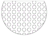
图7是根据本发明的一实施方式的液体分布组件的俯视结构示意图。Fig. 7 is a schematic top view of a liquid distribution assembly according to an embodiment of the present invention.
图8是根据本发明的另一实施方式的液体分布组件的俯视及侧视结构示意图。Fig. 8 is a top view and a side view schematic diagram of a liquid distribution assembly according to another embodiment of the present invention.
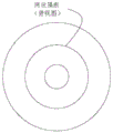
图9是根据本发明的一实施方式的第一溢流环的俯视结构示意图。Fig. 9 is a schematic top view of the first overflow ring according to an embodiment of the present invention.
图10是图8的第一溢流环的立体结构示意图。FIG. 10 is a schematic perspective view of the first overflow ring in FIG. 8 .
具体实施方式Detailed ways
下面结合附图对本发明做进一步说明。The present invention will be further described below in conjunction with the accompanying drawings.
如图1及图2所示为本发明的费托合成油加氢处理装置及工艺流程。费托合成油1送入加热炉28,加热到380℃~450℃后得到热原料油3,通过加氢反应器入口管线5进入加氢反应器反应腔6内的加氢反应器分离腔8中,经闪蒸和液体分布组件14分散后,其中较轻的部分被从底部向上流动的氢气带离向上进入加氢精制催化剂床层11(包括11-1~11-6);较重的部分向下被均匀的喷淋于加氢裂化催化剂床层12(包括12-1~12-6)上。同时,氢气2经加热炉28加热后的热氢4被送入加氢反应器反应腔6内,在网状挡板27及气体分布器4-1~4-6作用下,均匀从各反应区底部向上移动,与从液体分布组件喷淋的较重部分在加氢裂化催化剂床层12内逆流接触,并与从分离腔向上流动的较轻部分在加氢精制催化剂床层11内并流向上。在操作压力4MPa~15MPa压力下,费托合成油较重组分在加氢裂化催化剂床层上进行加氢裂化反应,一部分长链分子断裂为短链分子,多环芳烃也部分发生断环;费托合成油较轻组分、裂化反应轻组分和氢气在加氢精制催化剂床层11上进行烯烃加氢饱和,加氢脱氧及脱杂质等反应。Figure 1 and Figure 2 show the Fischer-Tropsch synthetic oil hydrotreating device and process flow of the present invention. The Fischer-Tropsch synthetic oil 1 is sent to the
加氢反应产生的较小分子的烃类或其它气体被氢气迅速带到分离器16中,经过混合段15和分离段13的分离作用,一部分较重的馏分向下经过加氢精制催化剂床层11、加氢反应器分离腔8和液体分布组件14均匀的落入加氢裂化催化剂床层12的表面。另外一部分轻组分在分离器内继续向其顶部的稳定段10移动,从分离器16顶端流出,继续通过分离器塔顶冷凝器17进行冷却,再经过分液罐18气液分离后,富氢和不凝气19外排,液态烃进行回流或抽出作为轻石脑馏分22。在分离器侧线150℃~190℃位置抽出重石脑油产品20,在分离器侧线300~380℃位置抽出柴油产品21。Smaller molecular hydrocarbons or other gases produced by the hydrogenation reaction are quickly brought to the
加氢反应器中的加氢重馏分23从加氢反应器重质油仓7流出,经循环油泵25作为回流重馏分24与原料油混合后作为加氢反应器的进料,也可部分作为尾油经循环油泵25排出装置。The hydrogenated
进一步地,在本发明的一个或多个示例性实施方式中,加氢反应器反应腔6可以为卧式储罐,如图1所示,其轴向沿横向设置,卧式储罐两端设有封头。进一步地,在本发明的一个或多个示例性实施方式中,反应腔6也可以为扁圆柱罐,其轴向沿纵向设置。Further, in one or more exemplary embodiments of the present invention, the reaction chamber 6 of the hydrogenation reactor can be a horizontal storage tank, as shown in FIG. With head. Further, in one or more exemplary embodiments of the present invention, the reaction chamber 6 may also be a flat cylindrical tank, the axial direction of which is arranged along the longitudinal direction.
进一步地,在本发明的一个或多个示例性实施方式中,隔板的形状与反应腔6的底部相匹配,当反应腔6为卧式储罐时,隔板为圆缺隔板,如图3和图4所示;当反应腔6为扁圆柱罐时,多个隔板为同轴环状隔板,如图5~图7所示。进一步地,在本发明的一个或多个示例性实施方式中,每个隔板上分布多个圆孔。进一步地,在本发明的一个或多个示例性实施方式中,如图1所示,多个网状挡板27可以向上延伸至加氢精制催化剂床层11,在底部不与催化剂床层11接触的隔板的开孔率小于70%,较低的开孔率有利于增加阻力,使得氢气尽可能向上进入加氢精制催化剂床层11,进一步起到气体分布器的作用。加氢精制催化剂床层11内的隔板的开孔率大于50%,有利于更充分地利用催化剂。Further, in one or more exemplary embodiments of the present invention, the shape of the partition matches the bottom of the reaction chamber 6, and when the reaction chamber 6 is a horizontal storage tank, the partition is a round partition, such as As shown in Figure 3 and Figure 4; when the reaction chamber 6 is a flat cylindrical tank, the plurality of partitions are coaxial annular partitions, as shown in Figures 5-7. Further, in one or more exemplary embodiments of the present invention, a plurality of round holes are distributed on each separator. Further, in one or more exemplary embodiments of the present invention, as shown in FIG. 1 , a plurality of mesh baffles 27 may extend upwards to the
进一步地,在本发明的一个或多个示例性实施方式中,分离器16由下至上包括混合段15、分离段13和稳定段10。Further, in one or more exemplary embodiments of the present invention, the
进一步地,在本发明的一个或多个示例性实施方式中,加氢反应器分离腔8底部设置的液体分布组件14包括液体分配盘和分配锥。液体分配盘设置在液体分布器的上方,液体分配盘与多孔催化剂层的顶面形状相同,液体分配盘上均匀开设多个第一通孔,第一通孔周围设有第一溢流环,分配盘外缘设有溢流部(图中未示出)。分配锥设置在液体分配盘的上部中心,分配锥设有多个第二通孔,第二通孔周围设有第二溢流环(图中未示出)。Further, in one or more exemplary embodiments of the present invention, the
优选而非限制性地,在本发明的一个或多个示例性实施方式中,结合图9和图10所示,第一溢流环的内侧设有锯齿部14-1,锯齿部向下弯曲,锯齿部上设有导流槽14-2。示例性地,导流槽沿锯齿部的中心开设。Preferably but not limitatively, in one or more exemplary embodiments of the present invention, as shown in FIG. 9 and FIG. 10 , the inner side of the first overflow ring is provided with a sawtooth portion 14-1, and the sawtooth portion is bent downward , The sawtooth part is provided with diversion groove 14-2. Exemplarily, the guide groove is opened along the center of the serrated part.
在本发明的一个或多个实施方式中,加氢反应器还包括辅助反应腔。应了解的是,辅助反应腔可以为多级。每一级辅助反应腔单独进氢、底部中心单独设置重质油仓,每一级辅助反应腔的液体原料进口与上一级的重质油仓相连接,多级辅助反应腔的顶部均连接至分离器16。In one or more embodiments of the present invention, the hydrogenation reactor further includes an auxiliary reaction chamber. It should be understood that the auxiliary reaction chamber may be multi-stage. Each level of auxiliary reaction chamber is fed with hydrogen separately, and the center of the bottom is equipped with a separate heavy oil tank. The liquid raw material inlet of each level of auxiliary reaction chamber is connected to the heavy oil tank of the previous level, and the top of the multi-level auxiliary reaction chamber is connected to to
下面结合具体实施例对本发明进一步说明,但应当理解本发明的保护范围并不受具体实施方式的限制。The present invention will be further described below in conjunction with specific examples, but it should be understood that the protection scope of the present invention is not limited by the specific embodiments.
实施例1Example 1
采用本发明图1及图2所示的装置及工艺流程,原料油为费托合成油,性质见表1。原料油和氢气经过加热炉加热至430℃后,进入加氢反应器,该加氢反应器内自上而下依次放置中国石化大连石油化工研究院生产的加氢精制催化剂FHUDS-5床层和加氢裂化催化剂FC-14床层,催化剂床层各自当量径高比为4:1,加氢精制催化剂床层高度及加氢裂化催化剂床层高度分别为800mm。加氢精制催化剂床层与加氢裂化催化剂床层间分离腔的高度为反应腔高度的15%。催化剂床层内设置环状隔板,隔板数量为4个。隔板上分布有多个孔;隔板向上延伸至催化剂层,催化剂层以下的隔板的开孔率40%,催化剂层内的隔板的开孔率70%。Using the device and process flow shown in Fig. 1 and Fig. 2 of the present invention, the raw oil is Fischer-Tropsch synthetic oil, and its properties are shown in Table 1. After the raw oil and hydrogen are heated to 430°C by the heating furnace, they enter the hydrogenation reactor. In the hydrogenation reactor, the hydrorefining catalyst FHUDS-5 bed produced by Sinopec Dalian Petrochemical Research Institute and the The bed of hydrocracking catalyst FC-14, the ratio of equivalent diameter to height of each catalyst bed is 4:1, the height of hydrofining catalyst bed and hydrocracking catalyst bed are 800mm respectively. The height of the separation chamber between the hydrorefining catalyst bed and the hydrocracking catalyst bed is 15% of the height of the reaction chamber. Ring-shaped partitions are arranged in the catalyst bed, and the number of partitions is four. A plurality of holes are distributed on the separator; the separator extends upward to the catalyst layer, the aperture ratio of the separator below the catalyst layer is 40%, and the aperture ratio of the separator in the catalyst layer is 70%.
原料液体首选经过液体分布组件进行轻、重组分分离,轻组分向上经加氢精制后进入分离器中,重组分进入加氢裂化催化剂床层中的4个不同子催化剂床层区域,与从底部进入的氢气在加氢裂化催化剂的作用下进行加氢裂化、烯烃饱和等反应。反应产生的轻馏分迅速向上脱离反应体系,并经加氢精制后进入分离器,分离器从下向上依次为混合段、分离段和稳定段,所述混合段高度为分离器总高度的30%,分离段高度为分离器总高度的65%;稳定段高度为分离器总高度的5%。混合段和稳定段放置填料拉西环。加氢精制后物流在分离器的混合段下部与轻组分混合后,继续向上,在混合段和分离段分离塔板作用下,重馏分向下重新进入加氢裂化催化剂床层进行裂化反应,轻馏分在侧线作为重石脑油馏分、柴油馏分被抽出作为产品送出,不凝气继续通过冷凝器进行冷却,再经过分液罐气液分离后,液态烃抽出作为轻石脑馏分,气体进入脱硫脱氨设备净化后循环利用。未足够裂化的重馏分从重质油仓底部流出经过循环泵后全部进入加氢处理装置入口作为循环油,具体操作工艺条件见表2,产品分布及性质见表4。The raw material liquid is firstly separated from the light and heavy components through the liquid distribution component. The light components enter the separator after being hydrotreated upwards, and the heavy components enter the four different sub-catalyst bed areas in the hydrocracking catalyst bed. The hydrogen entering from the bottom will undergo reactions such as hydrocracking and olefin saturation under the action of the hydrocracking catalyst. The light fraction produced by the reaction quickly leaves the reaction system upwards and enters the separator after hydrofining. The separator consists of a mixing section, a separating section and a stabilizing section from bottom to top, and the height of the mixing section is 30% of the total height of the separator , the height of the separation section is 65% of the total height of the separator; the height of the stable section is 5% of the total height of the separator. Raschig rings are placed in the mixing section and the stabilizing section. After hydrofinishing, the stream is mixed with the light components in the lower part of the mixing section of the separator, and then continues upwards. Under the action of the separation tray in the mixing section and the separation section, the heavy fractions re-enter the hydrocracking catalyst bed for cracking reaction downwards. The light fraction is taken out as a heavy naphtha fraction and diesel fraction in the side line and sent out as a product, and the non-condensable gas continues to be cooled by the condenser, and after gas-liquid separation in the liquid separation tank, the liquid hydrocarbon is extracted as a light naphtha fraction, and the gas enters the desulfurization The ammonia removal equipment is purified and recycled. The heavy distillates that are not sufficiently cracked flow out from the bottom of the heavy oil tank and pass through the circulation pump, and then all enter the inlet of the hydrotreating unit as circulating oil. The specific operating process conditions are shown in Table 2, and the product distribution and properties are shown in Table 4.
所述液体分布组件包括液体分布器及设置在液体分布器上方的液体分配盘及分配锥。所述液体分配盘与催化剂床层的顶面形状相同,液体分配盘的面积是催化剂床层横截面的70%。所述液体分配盘上均匀开设多个第一通孔,第一通孔周围设有第一溢流环,分配盘外缘设有溢流部,液体分配盘的开孔率为50%,第一通孔的直径为10mm,第一溢流环的高度为10mm。所述分配锥设置在液体分配盘的上部中心,分配锥设有多个第二通孔,第二通孔周围设有第二溢流环;分配锥的顶角120°,分配锥的开孔率为50%,第二溢流环的高度为10mm;分配锥的底面积为液体分配盘的面积的10%。The liquid distribution assembly includes a liquid distributor, a liquid distribution plate and a distribution cone arranged above the liquid distributor. The shape of the liquid distribution plate is the same as that of the top surface of the catalyst bed, and the area of the liquid distribution plate is 70% of the cross section of the catalyst bed. A plurality of first through holes are evenly opened on the liquid distribution plate, a first overflow ring is arranged around the first through holes, an overflow portion is provided on the outer edge of the distribution plate, the opening rate of the liquid distribution plate is 50%, and the first overflow ring is arranged around the first through hole. The diameter of a through hole is 10mm, and the height of the first overflow ring is 10mm. The distribution cone is arranged on the upper center of the liquid distribution plate, and the distribution cone is provided with a plurality of second through holes, and a second overflow ring is arranged around the second through holes; the apex angle of the distribution cone is 120°, and the opening of the distribution cone The ratio is 50%, the height of the second overflow ring is 10mm; the bottom area of the distribution cone is 10% of the area of the liquid distribution plate.
实施例2Example 2
本实施例与实施例1不同的是,加氢精制及加氢裂化催化剂床层当量径高分别比为5:1,催化剂床层内隔板数量为6个。隔板上分布有多个孔;隔板向上延伸至催化剂层,催化剂层以下的隔板的开孔率30%,催化剂层内的隔板的开孔率80%。液体分配盘的面积是催化剂床层横截面的90%。液体分配盘的开孔率为80%,第一通孔的直径为20mm,第一溢流环的高度为20mm。所述分配锥设置在液体分配盘的上部中心,分配锥设有多个第二通孔,第二通孔周围设有第二溢流环;分配锥的顶角150°,分配锥的开孔率为70%,第二溢流环的高度为20mm;分配锥的底面积为液体分配盘的面积的15%。其余条件与实施例1相同。The difference between this example and Example 1 is that the equivalent diameter-to-height ratio of the hydrofining and hydrocracking catalyst beds is 5:1, and the number of partitions in the catalyst bed is 6. A plurality of holes are distributed on the separator; the separator extends upward to the catalyst layer, the aperture ratio of the separator below the catalyst layer is 30%, and the aperture ratio of the separator in the catalyst layer is 80%. The area of the liquid distribution tray is 90% of the cross-section of the catalyst bed. The opening ratio of the liquid distribution plate is 80%, the diameter of the first through hole is 20 mm, and the height of the first overflow ring is 20 mm. The distribution cone is arranged on the upper center of the liquid distribution plate, and the distribution cone is provided with a plurality of second through holes, and a second overflow ring is arranged around the second through holes; the apex angle of the distribution cone is 150°, and the opening of the distribution cone The ratio is 70%, the height of the second overflow ring is 20mm; the bottom area of the distribution cone is 15% of the area of the liquid distribution plate. All the other conditions are the same as in Example 1.
实施例3Example 3
本实施例与实施例1不同的是,加氢精制及加氢裂化催化剂床层当量径高比为6:1,催化剂床层内隔板数量为6个。液体分配盘的面积是催化剂床层横截面的80%。液体分配盘的开孔率为70%,第一通孔的直径为30mm,第一溢流环的高度为20mm。所述分配锥设置在液体分配盘的上部中心,分配锥设有多个第二通孔,第二通孔周围设有第二溢流环;分配锥的顶角140°,分配锥的开孔率为60%,第二溢流环的高度为20mm;分配锥的底面积为液体分配盘的面积的15%。其余条件与实施例1相同。The difference between this example and Example 1 is that the equivalent diameter-to-height ratio of the hydrofining and hydrocracking catalyst bed is 6:1, and the number of partitions in the catalyst bed is 6. The area of the liquid distribution tray is 80% of the cross-section of the catalyst bed. The opening ratio of the liquid distribution plate is 70%, the diameter of the first through hole is 30 mm, and the height of the first overflow ring is 20 mm. The distribution cone is arranged on the upper center of the liquid distribution plate, and the distribution cone is provided with a plurality of second through holes, and a second overflow ring is arranged around the second through holes; the apex angle of the distribution cone is 140°, and the opening of the distribution cone The ratio is 60%, the height of the second overflow ring is 20mm; the bottom area of the distribution cone is 15% of the area of the liquid distribution plate. All the other conditions are the same as in Example 1.
实施例4Example 4
本实施例与实施例1不同的是,分离器的混合段高度为分离器总高度的25%,分离段高度为分离器总高度的65%;稳定段高度为分离器总高度的10%。其余条件与实施例1相同。The difference between this embodiment and Example 1 is that the height of the mixing section of the separator is 25% of the total height of the separator, the height of the separation section is 65% of the total height of the separator; the height of the stabilizing section is 10% of the total height of the separator. All the other conditions are the same as in Example 1.
比较例1Comparative example 1
采用常规的二段加氢法,即精制+裂化法工艺。精制和裂化反应器均采用原料和氢气并流从上向下流动的反应过程。费托合成油先在加氢精制反应器进行烯烃饱和,脱氧和脱杂质反应后,加氢精制物流进入第一分离、分馏系统,得到精制高压气体,石脑油、柴油和重油,其中精制高压气体回流进入加氢精制反应器,重油进入加氢裂化反应器进行加氢裂化反应,反应完成后进入第二分离、分馏系统,经分离得到气体、石脑油和柴油馏分,分离后的未裂化重组分全部回流进入加氢裂化反应器再次进行加氢裂化反应。采用的催化剂实施例1相同,工艺条件见表3。The conventional two-stage hydrogenation method is adopted, that is, refining + cracking process. Both refining and cracking reactors adopt a reaction process in which raw materials and hydrogen flow in parallel from top to bottom. Fischer-Tropsch synthetic oil is first saturated with olefins in the hydrotreating reactor, and after deoxygenation and impurity removal reactions, the hydrofinishing stream enters the first separation and fractionation system to obtain refined high-pressure gas, naphtha, diesel oil and heavy oil, among which refined high-pressure The gas flows back into the hydrotreating reactor, and the heavy oil enters the hydrocracking reactor for hydrocracking reaction. After the reaction is completed, it enters the second separation and fractionation system. After separation, gas, naphtha and diesel fractions are obtained. After separation, the uncracked All the heavy components are refluxed into the hydrocracking reactor to carry out the hydrocracking reaction again. The catalyst embodiment 1 adopted is the same, and the processing conditions are shown in Table 3.
表1原料油主要性质Table 1 Main Properties of Raw Oil
表2实施例工艺条件Table 2 embodiment technological conditions
表3比较例1工艺条件Table 3 Comparative Example 1 process conditions
表4产品分布和性质Table 4 Product distribution and properties
从表4的结果看,采用本发明方法,柴油的收率明显高于比较例1,且十六烷值大于83,是优质的柴油调和组分;石脑油馏分主要由烷烃组成,是优质的蒸汽裂解制乙烯、丙烯的原料。From the result of table 4, adopt the method of the present invention, the yield of diesel oil is obviously higher than that of comparative example 1, and cetane number is greater than 83, is high-quality diesel blending component; Naphtha fraction is mainly made up of alkane, is high-quality Raw materials for steam cracking of ethylene and propylene.
实施例5Example 5
实验室通过采用ansys19.0版本软件对实施例和比较例的床层反应温度分布进行了模拟计算。模拟条件按实施例和比较例的实际数据输入。模拟结果表明,传统固定床中心温度最高,从入口端到出口端,温度变化呈正态分布,本发明反应器床层温度比较均匀。床层模拟温升变化见表5。The laboratory simulated and calculated the bed reaction temperature distribution of the examples and comparative examples by using the ANSYS version 19.0 software. The simulation conditions are input according to the actual data of the examples and comparative examples. The simulation results show that the center temperature of the traditional fixed bed is the highest, and the temperature change from the inlet end to the outlet end shows a normal distribution, while the reactor bed temperature of the present invention is relatively uniform. Table 5 shows the simulated temperature rise of the bed.
表5床层模拟温升变化Table 5 Bed simulated temperature rise changes
由表5的结果可以看出,采用本发明的实施例1~实施例2中催化剂床层的温差明显比比较例1要低,从传统固定床28.1℃的温差降低到3.5℃,实施例平均温度与控制温度差值较小,说明本发明的反应器已经消除了加氢裂化反应的过热现象。As can be seen from the results in Table 5, the temperature difference of the catalyst bed in Embodiments 1 to 2 of the present invention is significantly lower than that of Comparative Example 1, from the temperature difference of 28.1° C. in the traditional fixed bed down to 3.5° C. The difference between the temperature and the control temperature is small, indicating that the reactor of the present invention has eliminated the overheating phenomenon of the hydrocracking reaction.
Claims (16)
Priority Applications (1)
| Application Number | Priority Date | Filing Date | Title |
|---|---|---|---|
| CN202111268117.4A CN116064131B (en) | 2021-10-29 | 2021-10-29 | A Fischer-Tropsch synthetic oil hydroprocessing device and method |
Applications Claiming Priority (1)
| Application Number | Priority Date | Filing Date | Title |
|---|---|---|---|
| CN202111268117.4A CN116064131B (en) | 2021-10-29 | 2021-10-29 | A Fischer-Tropsch synthetic oil hydroprocessing device and method |
Publications (2)
| Publication Number | Publication Date |
|---|---|
| CN116064131A true CN116064131A (en) | 2023-05-05 |
| CN116064131B CN116064131B (en) | 2024-12-06 |
Family
ID=86168462
Family Applications (1)
| Application Number | Title | Priority Date | Filing Date |
|---|---|---|---|
| CN202111268117.4A Active CN116064131B (en) | 2021-10-29 | 2021-10-29 | A Fischer-Tropsch synthetic oil hydroprocessing device and method |
Country Status (1)
| Country | Link |
|---|---|
| CN (1) | CN116064131B (en) |
Citations (3)
| Publication number | Priority date | Publication date | Assignee | Title |
|---|---|---|---|---|
| CN102876371A (en) * | 2011-07-11 | 2013-01-16 | 中国石油化工股份有限公司 | Inferior raw material hydrocracking method |
| CN105778995A (en) * | 2016-04-18 | 2016-07-20 | 武汉凯迪工程技术研究总院有限公司 | Method and device for producing good-quality diesel oil through combined hydrogenation of low-temperature Fischer-Tropsch synthesis oil and inferior crude oil |
| CN112705120A (en) * | 2019-10-25 | 2021-04-27 | 中国石油化工股份有限公司 | Heavy oil processing device and processing method |
-
2021
- 2021-10-29 CN CN202111268117.4A patent/CN116064131B/en active Active
Patent Citations (3)
| Publication number | Priority date | Publication date | Assignee | Title |
|---|---|---|---|---|
| CN102876371A (en) * | 2011-07-11 | 2013-01-16 | 中国石油化工股份有限公司 | Inferior raw material hydrocracking method |
| CN105778995A (en) * | 2016-04-18 | 2016-07-20 | 武汉凯迪工程技术研究总院有限公司 | Method and device for producing good-quality diesel oil through combined hydrogenation of low-temperature Fischer-Tropsch synthesis oil and inferior crude oil |
| CN112705120A (en) * | 2019-10-25 | 2021-04-27 | 中国石油化工股份有限公司 | Heavy oil processing device and processing method |
Also Published As
| Publication number | Publication date |
|---|---|
| CN116064131B (en) | 2024-12-06 |
Similar Documents
| Publication | Publication Date | Title |
|---|---|---|
| KR102900131B1 (en) | Reaction system and reaction method of multiphase combination | |
| KR102952547B1 (en) | Liquid-phase reactors and their applications | |
| CN116064122B (en) | Method and device for producing aromatic hydrocarbon raw material by coal tar hydrogenation treatment | |
| CN116064128B (en) | A Fischer-Tropsch synthetic oil hydrocatalytic distillation device and method | |
| CN115785994B (en) | Wax oil hydrogenation method and device | |
| CN116064123B (en) | Method and device for producing aromatic hydrocarbon raw material by catalytic cracking light cycle oil hydrotreatment | |
| CN116064131B (en) | A Fischer-Tropsch synthetic oil hydroprocessing device and method | |
| CN116948688B (en) | A gasoline catalytic distillation desulfurization device and method | |
| CN116064130B (en) | Hydrogenation quality improvement method and device for Fischer-Tropsch synthetic oil | |
| CN116064129B (en) | Fischer-Tropsch synthesis oil hydrogenation method and device | |
| CN116064127B (en) | Hydrotreatment device and method for producing aviation kerosene from Fischer-Tropsch synthetic oil | |
| CN116064126B (en) | Fischer-Tropsch synthesis oil hydrogenation device and method | |
| CN115785993B (en) | Diesel hydrogenation method and device | |
| CN116948672A (en) | A device and method for hydrogenating bio-oil to produce low-aromatic solvent oil | |
| CN115785995B (en) | Inferior diesel oil hydrotreating method and device | |
| CN116064121B (en) | Coal tar hydrotreating method and device | |
| CN116064120A (en) | Coal tar two-stage hydrogenation treatment device and method | |
| CN116948689B (en) | A method and device for hydrotreating low-quality diesel | |
| CN116064125B (en) | A hydrogenation device and method for producing light oil products from Fischer-Tropsch synthetic oil | |
| CN116948690B (en) | Hydrotreating method and device for producing high-aromatic naphtha and BTX from inferior diesel | |
| CN115785992B (en) | Inferior diesel oil hydrogenation process startup method | |
| CN116948673B (en) | A device for producing low aromatic solvent oil and a hydrogenation method | |
| CN116064146B (en) | One-stage series hydrocracking method | |
| CN116064148B (en) | A two-stage hydrocracking method | |
| CN116948693A (en) | A method and device for catalyzing diesel fuel to produce high-light aromatic naphtha |
Legal Events
| Date | Code | Title | Description |
|---|---|---|---|
| PB01 | Publication | ||
| PB01 | Publication | ||
| SE01 | Entry into force of request for substantive examination | ||
| SE01 | Entry into force of request for substantive examination | ||
| TA01 | Transfer of patent application right |
Effective date of registration: 20240129 Address after: 100728 No. 22 North Main Street, Chaoyang District, Beijing, Chaoyangmen Applicant after: CHINA PETROLEUM & CHEMICAL Corp. Country or region after: China Applicant after: Sinopec (Dalian) Petrochemical Research Institute Co.,Ltd. Address before: 100020 No. 22 North Main Street, Chaoyang District, Beijing, Chaoyangmen Applicant before: CHINA PETROLEUM & CHEMICAL Corp. Country or region before: China Applicant before: DALIAN RESEARCH INSTITUTE OF PETROLEUM AND PETROCHEMICALS, SINOPEC Corp. |
|
| TA01 | Transfer of patent application right | ||
| GR01 | Patent grant | ||
| GR01 | Patent grant |