CN115958734A - Device, die set and method for manufacturing metal-resin composite - Google Patents
Device, die set and method for manufacturing metal-resin composite Download PDFInfo
- Publication number
- CN115958734A CN115958734A CN202211206512.4A CN202211206512A CN115958734A CN 115958734 A CN115958734 A CN 115958734A CN 202211206512 A CN202211206512 A CN 202211206512A CN 115958734 A CN115958734 A CN 115958734A
- Authority
- CN
- China
- Prior art keywords
- metal
- forming
- mold
- resin material
- auxiliary
- Prior art date
- Legal status (The legal status is an assumption and is not a legal conclusion. Google has not performed a legal analysis and makes no representation as to the accuracy of the status listed.)
- Pending
Links
Images


Classifications
-
- B—PERFORMING OPERATIONS; TRANSPORTING
- B29—WORKING OF PLASTICS; WORKING OF SUBSTANCES IN A PLASTIC STATE IN GENERAL
- B29C—SHAPING OR JOINING OF PLASTICS; SHAPING OF MATERIAL IN A PLASTIC STATE, NOT OTHERWISE PROVIDED FOR; AFTER-TREATMENT OF THE SHAPED PRODUCTS, e.g. REPAIRING
- B29C43/00—Compression moulding, i.e. applying external pressure to flow the moulding material; Apparatus therefor
- B29C43/02—Compression moulding, i.e. applying external pressure to flow the moulding material; Apparatus therefor of articles of definite length, i.e. discrete articles
- B29C43/18—Compression moulding, i.e. applying external pressure to flow the moulding material; Apparatus therefor of articles of definite length, i.e. discrete articles incorporating preformed parts or layers, e.g. compression moulding around inserts or for coating articles
-
- B—PERFORMING OPERATIONS; TRANSPORTING
- B29—WORKING OF PLASTICS; WORKING OF SUBSTANCES IN A PLASTIC STATE IN GENERAL
- B29C—SHAPING OR JOINING OF PLASTICS; SHAPING OF MATERIAL IN A PLASTIC STATE, NOT OTHERWISE PROVIDED FOR; AFTER-TREATMENT OF THE SHAPED PRODUCTS, e.g. REPAIRING
- B29C45/00—Injection moulding, i.e. forcing the required volume of moulding material through a nozzle into a closed mould; Apparatus therefor
- B29C45/14—Injection moulding, i.e. forcing the required volume of moulding material through a nozzle into a closed mould; Apparatus therefor incorporating preformed parts or layers, e.g. injection moulding around inserts or for coating articles
- B29C45/1418—Injection moulding, i.e. forcing the required volume of moulding material through a nozzle into a closed mould; Apparatus therefor incorporating preformed parts or layers, e.g. injection moulding around inserts or for coating articles the inserts being deformed or preformed, e.g. by the injection pressure
-
- B—PERFORMING OPERATIONS; TRANSPORTING
- B21—MECHANICAL METAL-WORKING WITHOUT ESSENTIALLY REMOVING MATERIAL; PUNCHING METAL
- B21D—WORKING OR PROCESSING OF SHEET METAL OR METAL TUBES, RODS OR PROFILES WITHOUT ESSENTIALLY REMOVING MATERIAL; PUNCHING METAL
- B21D22/00—Shaping without cutting, by stamping, spinning, or deep-drawing
- B21D22/20—Deep-drawing
- B21D22/21—Deep-drawing without fixing the border of the blank
-
- B—PERFORMING OPERATIONS; TRANSPORTING
- B21—MECHANICAL METAL-WORKING WITHOUT ESSENTIALLY REMOVING MATERIAL; PUNCHING METAL
- B21D—WORKING OR PROCESSING OF SHEET METAL OR METAL TUBES, RODS OR PROFILES WITHOUT ESSENTIALLY REMOVING MATERIAL; PUNCHING METAL
- B21D35/00—Combined processes according to or processes combined with methods covered by groups B21D1/00 - B21D31/00
- B21D35/002—Processes combined with methods covered by groups B21D1/00 - B21D31/00
- B21D35/005—Processes combined with methods covered by groups B21D1/00 - B21D31/00 characterized by the material of the blank or the workpiece
- B21D35/007—Layered blanks
-
- B—PERFORMING OPERATIONS; TRANSPORTING
- B21—MECHANICAL METAL-WORKING WITHOUT ESSENTIALLY REMOVING MATERIAL; PUNCHING METAL
- B21D—WORKING OR PROCESSING OF SHEET METAL OR METAL TUBES, RODS OR PROFILES WITHOUT ESSENTIALLY REMOVING MATERIAL; PUNCHING METAL
- B21D47/00—Making rigid structural elements or units, e.g. honeycomb structures
- B21D47/04—Making rigid structural elements or units, e.g. honeycomb structures composite sheet metal profiles
-
- B—PERFORMING OPERATIONS; TRANSPORTING
- B29—WORKING OF PLASTICS; WORKING OF SUBSTANCES IN A PLASTIC STATE IN GENERAL
- B29C—SHAPING OR JOINING OF PLASTICS; SHAPING OF MATERIAL IN A PLASTIC STATE, NOT OTHERWISE PROVIDED FOR; AFTER-TREATMENT OF THE SHAPED PRODUCTS, e.g. REPAIRING
- B29C43/00—Compression moulding, i.e. applying external pressure to flow the moulding material; Apparatus therefor
- B29C43/32—Component parts, details or accessories; Auxiliary operations
- B29C43/36—Moulds for making articles of definite length, i.e. discrete articles
-
- B—PERFORMING OPERATIONS; TRANSPORTING
- B29—WORKING OF PLASTICS; WORKING OF SUBSTANCES IN A PLASTIC STATE IN GENERAL
- B29C—SHAPING OR JOINING OF PLASTICS; SHAPING OF MATERIAL IN A PLASTIC STATE, NOT OTHERWISE PROVIDED FOR; AFTER-TREATMENT OF THE SHAPED PRODUCTS, e.g. REPAIRING
- B29C43/00—Compression moulding, i.e. applying external pressure to flow the moulding material; Apparatus therefor
- B29C43/32—Component parts, details or accessories; Auxiliary operations
- B29C43/52—Heating or cooling
-
- B—PERFORMING OPERATIONS; TRANSPORTING
- B29—WORKING OF PLASTICS; WORKING OF SUBSTANCES IN A PLASTIC STATE IN GENERAL
- B29C—SHAPING OR JOINING OF PLASTICS; SHAPING OF MATERIAL IN A PLASTIC STATE, NOT OTHERWISE PROVIDED FOR; AFTER-TREATMENT OF THE SHAPED PRODUCTS, e.g. REPAIRING
- B29C45/00—Injection moulding, i.e. forcing the required volume of moulding material through a nozzle into a closed mould; Apparatus therefor
- B29C45/14—Injection moulding, i.e. forcing the required volume of moulding material through a nozzle into a closed mould; Apparatus therefor incorporating preformed parts or layers, e.g. injection moulding around inserts or for coating articles
- B29C45/1418—Injection moulding, i.e. forcing the required volume of moulding material through a nozzle into a closed mould; Apparatus therefor incorporating preformed parts or layers, e.g. injection moulding around inserts or for coating articles the inserts being deformed or preformed, e.g. by the injection pressure
- B29C45/14221—Injection moulding, i.e. forcing the required volume of moulding material through a nozzle into a closed mould; Apparatus therefor incorporating preformed parts or layers, e.g. injection moulding around inserts or for coating articles the inserts being deformed or preformed, e.g. by the injection pressure by tools, e.g. cutting means
-
- B—PERFORMING OPERATIONS; TRANSPORTING
- B29—WORKING OF PLASTICS; WORKING OF SUBSTANCES IN A PLASTIC STATE IN GENERAL
- B29C—SHAPING OR JOINING OF PLASTICS; SHAPING OF MATERIAL IN A PLASTIC STATE, NOT OTHERWISE PROVIDED FOR; AFTER-TREATMENT OF THE SHAPED PRODUCTS, e.g. REPAIRING
- B29C70/00—Shaping composites, i.e. plastics material comprising reinforcements, fillers or preformed parts, e.g. inserts
- B29C70/04—Shaping composites, i.e. plastics material comprising reinforcements, fillers or preformed parts, e.g. inserts comprising reinforcements only, e.g. self-reinforcing plastics
- B29C70/28—Shaping operations therefor
- B29C70/40—Shaping or impregnating by compression not applied
- B29C70/42—Shaping or impregnating by compression not applied for producing articles of definite length, i.e. discrete articles
- B29C70/46—Shaping or impregnating by compression not applied for producing articles of definite length, i.e. discrete articles using matched moulds, e.g. for deforming sheet moulding compounds [SMC] or prepregs
-
- B—PERFORMING OPERATIONS; TRANSPORTING
- B29—WORKING OF PLASTICS; WORKING OF SUBSTANCES IN A PLASTIC STATE IN GENERAL
- B29C—SHAPING OR JOINING OF PLASTICS; SHAPING OF MATERIAL IN A PLASTIC STATE, NOT OTHERWISE PROVIDED FOR; AFTER-TREATMENT OF THE SHAPED PRODUCTS, e.g. REPAIRING
- B29C70/00—Shaping composites, i.e. plastics material comprising reinforcements, fillers or preformed parts, e.g. inserts
- B29C70/68—Shaping composites, i.e. plastics material comprising reinforcements, fillers or preformed parts, e.g. inserts by incorporating or moulding on preformed parts, e.g. inserts or layers, e.g. foam blocks
- B29C70/78—Moulding material on one side only of the preformed part
-
- B—PERFORMING OPERATIONS; TRANSPORTING
- B29—WORKING OF PLASTICS; WORKING OF SUBSTANCES IN A PLASTIC STATE IN GENERAL
- B29C—SHAPING OR JOINING OF PLASTICS; SHAPING OF MATERIAL IN A PLASTIC STATE, NOT OTHERWISE PROVIDED FOR; AFTER-TREATMENT OF THE SHAPED PRODUCTS, e.g. REPAIRING
- B29C43/00—Compression moulding, i.e. applying external pressure to flow the moulding material; Apparatus therefor
- B29C43/02—Compression moulding, i.e. applying external pressure to flow the moulding material; Apparatus therefor of articles of definite length, i.e. discrete articles
- B29C43/18—Compression moulding, i.e. applying external pressure to flow the moulding material; Apparatus therefor of articles of definite length, i.e. discrete articles incorporating preformed parts or layers, e.g. compression moulding around inserts or for coating articles
- B29C2043/185—Compression moulding, i.e. applying external pressure to flow the moulding material; Apparatus therefor of articles of definite length, i.e. discrete articles incorporating preformed parts or layers, e.g. compression moulding around inserts or for coating articles using adhesives
-
- B—PERFORMING OPERATIONS; TRANSPORTING
- B29—WORKING OF PLASTICS; WORKING OF SUBSTANCES IN A PLASTIC STATE IN GENERAL
- B29C—SHAPING OR JOINING OF PLASTICS; SHAPING OF MATERIAL IN A PLASTIC STATE, NOT OTHERWISE PROVIDED FOR; AFTER-TREATMENT OF THE SHAPED PRODUCTS, e.g. REPAIRING
- B29C43/00—Compression moulding, i.e. applying external pressure to flow the moulding material; Apparatus therefor
- B29C43/02—Compression moulding, i.e. applying external pressure to flow the moulding material; Apparatus therefor of articles of definite length, i.e. discrete articles
- B29C43/18—Compression moulding, i.e. applying external pressure to flow the moulding material; Apparatus therefor of articles of definite length, i.e. discrete articles incorporating preformed parts or layers, e.g. compression moulding around inserts or for coating articles
- B29C2043/189—Compression moulding, i.e. applying external pressure to flow the moulding material; Apparatus therefor of articles of definite length, i.e. discrete articles incorporating preformed parts or layers, e.g. compression moulding around inserts or for coating articles the parts being joined
-
- B—PERFORMING OPERATIONS; TRANSPORTING
- B29—WORKING OF PLASTICS; WORKING OF SUBSTANCES IN A PLASTIC STATE IN GENERAL
- B29K—INDEXING SCHEME ASSOCIATED WITH SUBCLASSES B29B, B29C OR B29D, RELATING TO MOULDING MATERIALS OR TO MATERIALS FOR MOULDS, REINFORCEMENTS, FILLERS OR PREFORMED PARTS, e.g. INSERTS
- B29K2705/00—Use of metals, their alloys or their compounds, for preformed parts, e.g. for inserts
-
- B—PERFORMING OPERATIONS; TRANSPORTING
- B29—WORKING OF PLASTICS; WORKING OF SUBSTANCES IN A PLASTIC STATE IN GENERAL
- B29L—INDEXING SCHEME ASSOCIATED WITH SUBCLASS B29C, RELATING TO PARTICULAR ARTICLES
- B29L2031/00—Other particular articles
- B29L2031/30—Vehicles, e.g. ships or aircraft, or body parts thereof
- B29L2031/3002—Superstructures characterized by combining metal and plastics, i.e. hybrid parts
Landscapes
- Engineering & Computer Science (AREA)
- Mechanical Engineering (AREA)
- Chemical & Material Sciences (AREA)
- Composite Materials (AREA)
- Manufacturing & Machinery (AREA)
- Moulds For Moulding Plastics Or The Like (AREA)
- Casting Or Compression Moulding Of Plastics Or The Like (AREA)
Abstract
Description
技术领域technical field
本发明涉及用来制造金属树脂复合体的装置、金属模套件(set)以及方法。The present invention relates to an apparatus, a metal mold set, and a method for manufacturing a metal-resin composite body.
背景技术Background technique
已知有用来将金属部件及具有热固化性的树脂材料加压成形而制造金属树脂复合体的装置(例如专利文献1)。上述金属树脂复合体通过将用与上述装置另外的加压装置预先加压成形的金属部件和树脂材料用上述装置加压成形而被一体地成形。即,在上述金属树脂复合体的制造中,使用用来将金属部件加压成形的金属模和用来将金属部件和树脂材料一体地成形的金属模。There is known an apparatus for producing a metal-resin composite by press-molding a metal member and a thermosetting resin material (for example, Patent Document 1). The above-mentioned metal-resin composite is integrally molded by press-molding a metal member and a resin material previously press-molded by a press device separate from the above-mentioned device. That is, in the production of the above-mentioned metal-resin composite, a metal mold for press-forming the metal part and a metal mold for integrally molding the metal part and the resin material are used.
现有技术文献prior art literature
专利文献patent documents
专利文献1:日本特开2020-104411号公报。Patent Document 1: Japanese Patent Laid-Open No. 2020-104411.
发明内容Contents of the invention
发明要解决的课题The problem to be solved by the invention
在使用1组金属模将上述金属树脂复合体成形的情况下,在将金属部件加压成形为规定的形状后,使用在金属部件的加压成形中使用过的金属模将金属部件和树脂材料加压成形。在此情况下,由于将金属模的腔室(cavity)匹配于金属树脂复合体的形状、即金属部件和树脂材料被一体成形的最终形状而设计,所以沿着下模的金属部件的加压成形较难,金属部件的成形精度有可能下降。In the case of molding the above-mentioned metal-resin composite using a set of metal molds, after press-forming the metal parts into a predetermined shape, the metal parts and the resin material Pressure forming. In this case, since the cavity (cavity) of the metal mold is designed to match the shape of the metal-resin composite, that is, the final shape in which the metal part and the resin material are integrally formed, the pressurization of the metal part along the lower die Forming is difficult, and the forming accuracy of metal parts may decrease.
本发明的目的是在用来借助1组金属模制造金属树脂复合体的装置、金属模套件以及方法中,实现金属部件的成形精度的提高。An object of the present invention is to improve the forming accuracy of metal parts in an apparatus, a mold set, and a method for manufacturing a metal-resin composite with a set of metal molds.
用来解决课题的手段means to solve problems
本发明的第1方案提供一种用来制造金属树脂复合体的装置,是用来将金属部件及树脂材料加压成形而制造金属树脂复合体的装置,具备:金属模,该金属模具备上模及下模,所述上模及下模将前述金属部件及前述树脂材料夹入;成形辅助零件,能够拆装地被固定在前述上模,以将由前述上模及前述下模形成的用来配置前述树脂材料的腔室的至少一部分填埋;以及驱动部,使前述上模及前述下模的至少一方在铅直方向上移动;前述成形辅助零件具有用来将前述金属部件成形的第1加压面;前述上模具有用来将前述金属部件和前述树脂材料一体成形的第2加压面;安装着前述成形辅助零件的状态下的前述第1加压面与前述下模之间的距离比前述成形辅助零件被拆下的状态下的前述第2加压面与前述下模之间的距离短。A first aspect of the present invention provides an apparatus for manufacturing a metal-resin composite body, which is an apparatus for manufacturing a metal-resin composite body by press-forming a metal part and a resin material, and includes: a metal mold, and the metal mold has an upper The upper mold and the lower mold sandwich the aforementioned metal parts and the aforementioned resin material; the forming auxiliary parts are detachably fixed to the aforementioned upper mold so that at least a part of the cavity for disposing the resin material is buried; and a drive unit moves at least one of the upper die and the lower die in the vertical direction; Pressure surface; the upper mold has a second pressure surface for integrally molding the metal part and the resin material; the distance between the first pressure surface and the lower mold in the state where the auxiliary molding parts are installed The distance between the second pressurizing surface and the lower die is shorter than that in a state in which the auxiliary molding parts are removed.
在用1组金属模进行金属部件的加压成形和金属部件及树脂材料的一体成形的情况下,在上模及下模闭合的状态下形成配置树脂材料的腔室。因此,在金属部件的加压成形时,在形成有其腔室的部位,上模不能使金属部件沿着下模的成形面的形状成形。相对于此,根据该结构,可以首先在将金属部件加压成形时将成形辅助零件安装于上模,接着在将金属树脂复合体加压成形时将成形辅助零件从上模拆下。此外,安装着成形辅助零件的状态下的第1加压面与下模之间的距离成为比成形辅助零件被拆下的状态下的第2加压面与下模之间的距离短。即,由于在金属部件的加压成形时由成形辅助零件将腔室的至少一部分填埋,所以腔室减少,在金属部件的加压成形时,金属部件变得容易沿着下模的形状。结果,能够提高金属部件的成形精度。而且,通过在将金属树脂复合体加压成形时将成形辅助零件拆下,能够形成希望的大小及形状的腔室,所以能够制造希望的形状的金属树脂复合体。In the case of press-molding the metal part and integrally molding the metal part and the resin material with a set of metal molds, the cavity in which the resin material is placed is formed with the upper mold and the lower mold closed. Therefore, when the metal part is press-formed, the upper die cannot form the metal part along the shape of the forming surface of the lower die at the portion where the cavity is formed. On the other hand, according to this configuration, the auxiliary molding parts can be first attached to the upper die when the metal member is press-molded, and then the auxiliary molding parts can be removed from the upper die when the metal-resin composite is press-molded. In addition, the distance between the first pressurizing surface and the lower die in the state where the auxiliary forming parts are attached is shorter than the distance between the second pressurizing surface and the lower die when the auxiliary forming parts are removed. That is, since at least a part of the cavity is filled by the forming auxiliary parts during press forming of the metal part, the number of cavities is reduced, and the metal part easily conforms to the shape of the lower mold during press forming of the metal part. As a result, the forming accuracy of the metal part can be improved. Furthermore, by removing the molding auxiliary parts when the metal-resin composite is press-molded, a cavity of a desired size and shape can be formed, so a metal-resin composite of a desired shape can be manufactured.
也可以是,前述金属树脂复合体在与长边方向垂直的截面中,具有在水平方向上延伸的底壁部、从前述底壁部的两端立起的侧壁部、以及从前述侧壁部向水平方向外侧延伸的凸缘部;前述上模在前述截面中,具有将前述底壁部成形的第1成形上表面、将前述侧壁部成形的第2成形上表面、以及将前述凸缘部成形的第3成形上表面;前述成形辅助零件被配置为,将由前述第1成形上表面及前述第2成形上表面形成的角部覆盖。In a cross-section perpendicular to the longitudinal direction, the metal-resin composite may have a bottom wall extending in the horizontal direction, side walls standing from both ends of the bottom wall, and side walls extending from the side walls. The flange part extending outward in the horizontal direction; the above-mentioned upper mold has a first forming upper surface for forming the aforementioned bottom wall part, a second forming upper surface for forming the aforementioned side wall part, and the aforementioned convex part in the aforementioned section. A third molding upper surface for edge molding; the auxiliary molding parts are arranged to cover corners formed by the first molding upper surface and the second molding upper surface.
根据该结构,角部处的腔室减少。在腔室减少的部位,在金属部件的加压成形时金属部件变得容易沿着下模的形状,所以能够提高金属部件的成形精度。特别是,由于在角部被要求成形精度,所以在角部使腔室减少来提高尺寸精度是有效的。According to this structure, the chamber at the corner is reduced. In the portion where the number of cavities is reduced, the metal part tends to follow the shape of the lower mold when the metal part is press-formed, so that the forming accuracy of the metal part can be improved. In particular, since forming accuracy is required at the corners, it is effective to increase the dimensional accuracy by reducing the number of cavities at the corners.
也可以是,在前述第2成形上表面设置有阶差。Alternatively, a step may be provided on the second molding upper surface.
根据该结构,树脂材料为了从腔室漏出需要越过上模的阶差而流动,所以能够由阶差将腔室封闭。因而,能够抑制树脂材料的漏出。即,能够提高树脂材料的腔室中的填充压力,提高品质。According to this configuration, since the resin material needs to flow over the step of the upper mold in order to leak out of the cavity, the cavity can be closed by the step. Therefore, leakage of the resin material can be suppressed. That is, it is possible to increase the filling pressure in the cavity of the resin material and improve the quality.
也可以是,前述成形辅助零件能够拆装地被固定在前述上模,以将前述腔室的全部填埋。The auxiliary forming part may be detachably fixed to the upper die so as to fill up the entire cavity.
根据该结构,在成形辅助零件被安装于上模的状态下将上模及下模闭合的情况下,由于没有腔室,所以在金属部件的加压成形时金属部件变得容易沿着下模的形状。因此,能够提高金属部件的成形精度。According to this structure, when the upper mold and the lower mold are closed with the forming auxiliary parts attached to the upper mold, since there is no cavity, the metal part becomes easy to follow the lower mold when the metal part is press-molded. shape. Therefore, the forming accuracy of the metal part can be improved.
也可以是,在前述成形辅助零件设置有贯通孔;在前述上模,设置有被与前述贯通孔对位的螺纹孔;通过将螺纹件经由前述贯通孔紧固于前述螺纹孔,前述成形辅助零件被固定在前述上模。It may also be that a through hole is provided in the aforementioned forming auxiliary part; a threaded hole aligned with the aforementioned through hole is provided in the aforementioned upper mold; Parts are fixed on the aforementioned upper die.
根据该结构,能够将成形辅助零件机械性地牢固地固定在上模。因此,能够抑制或防止在加压成形时成形辅助零件从上模脱离。According to this configuration, the auxiliary forming part can be mechanically and firmly fixed to the upper mold. Therefore, it is possible to suppress or prevent the forming auxiliary part from coming off from the upper die during press forming.
本发明的第2方案提供一种用来制造金属树脂复合体的金属模套件,是用来将金属部件及树脂材料加压成形而制造金属树脂复合体的金属模套件,具备:金属模,该金属模具备上模及下模,所述上模及下模将前述金属部件及前述树脂材料夹入;以及成形辅助零件,能够拆装地被固定在前述上模,以将由前述上模及前述下模形成的用来配置前述树脂材料的腔室的至少一部分填埋;前述成形辅助零件具有用来将前述金属部件成形的第1加压面;前述上模具有用来将前述金属部件和前述树脂材料一体成形的第2加压面;安装着前述成形辅助零件的状态下的前述第1加压面与前述下模之间的距离比前述成形辅助零件被拆下的状态下的前述第2加压面与前述下模之间的距离短。A second aspect of the present invention provides a metal mold set for manufacturing a metal-resin composite, which is a metal mold set for press-forming a metal part and a resin material to manufacture a metal-resin composite, comprising: a metal mold, the The metal mold includes an upper mold and a lower mold for sandwiching the aforementioned metal member and the aforementioned resin material; At least a part of the cavity formed by the lower die for disposing the resin material is buried; the forming auxiliary part has a first pressure surface for forming the metal part; the upper die is used for forming the metal part and the resin The second pressing surface where the material is integrally molded; the distance between the first pressing surface and the lower mold in the state where the auxiliary forming parts are installed is larger than the second pressing surface in the state where the auxiliary forming parts are removed. The distance between the pressing surface and the aforementioned lower die is short.
在用1组金属模进行金属部件的加压成形和金属部件及树脂材料的一体成形的情况下,在上模及下模闭合的状态下形成配置树脂材料的腔室。因此,在金属部件的加压成形时,在形成有其腔室的部位,上模不能使金属部件沿着下模的成形面的形状成形。相对于此,根据该结构,可以首先在将金属部件加压成形时将成形辅助零件安装于上模,接着在将金属树脂复合体加压成形时将成形辅助零件从上模拆下。由此,在金属部件的加压成形时由成形辅助零件将腔室的至少一部分填埋,所以腔室减少,在金属部件的加压成形时金属部件变得容易沿着下模的形状。结果,能够提高金属部件的成形精度。而且,通过在将金属树脂复合体加压成形时将成形辅助零件拆下,能够形成希望的大小及形状的腔室,所以能够制造希望的形状的金属树脂复合体。In the case of press-molding the metal part and integrally molding the metal part and the resin material with a set of metal molds, the cavity in which the resin material is placed is formed with the upper mold and the lower mold closed. Therefore, when the metal part is press-formed, the upper die cannot form the metal part along the shape of the forming surface of the lower die at the portion where the cavity is formed. On the other hand, according to this configuration, the auxiliary molding parts can be first attached to the upper die when the metal member is press-molded, and then the auxiliary molding parts can be removed from the upper die when the metal-resin composite is press-molded. Thereby, at least a part of the cavity is filled by the forming auxiliary part during press molding of the metal part, so the number of cavities is reduced, and the metal part easily conforms to the shape of the lower mold during press molding of the metal part. As a result, the forming accuracy of the metal part can be improved. Furthermore, by removing the molding auxiliary parts when the metal-resin composite is press-molded, a cavity of a desired size and shape can be formed, so a metal-resin composite of a desired shape can be manufactured.
本发明的第3方案提供一种用来制造金属树脂复合体的方法,是用来将金属部件及树脂材料加压成形而制造金属树脂复合体的方法,包括:准备金属模和成形辅助零件,所述金属模具备上模及下模,所述上模及下模将前述金属部件及前述树脂材料夹入,所述成形辅助零件能够拆装地被固定在前述上模,以将由前述上模及前述下模形成的用来配置前述树脂材料的腔室的至少一部分填埋;将安装着前述成形辅助零件的前述上模及前述下模闭合,将前述金属部件加压成形;将安装着前述成形辅助零件的前述上模及前述下模打开,在加压成形出的前述金属部件之上配置前述树脂材料;以及将前述成形辅助零件被拆下的前述上模及前述下模闭合,将前述金属部件及前述树脂材料一体成形。The third aspect of the present invention provides a method for manufacturing a metal-resin composite, which is a method for press-forming a metal part and a resin material to manufacture a metal-resin composite, comprising: preparing a metal mold and forming auxiliary parts, The metal mold includes an upper mold and a lower mold sandwiching the metal member and the resin material, and the molding auxiliary parts are detachably fixed to the upper mold so that And at least a part of the cavity formed by the lower mold for disposing the aforementioned resin material is buried; the aforementioned upper mold and the aforementioned lower mold with the aforementioned forming auxiliary parts installed are closed, and the aforementioned metal parts are press-formed; the aforementioned The upper mold and the lower mold of the auxiliary forming parts are opened, and the resin material is placed on the metal part formed by pressurization; and the upper mold and the lower mold from which the auxiliary forming parts are removed are closed, and the The metal part and the aforementioned resin material are integrally formed.
在用1组金属模进行金属部件的加压成形和金属部件及树脂材料的一体成形的情况下,在上模及下模闭合的状态下形成配置树脂材料的腔室。因此,在金属部件的加压成形时,在形成有其腔室的部位,上模不能使金属部件沿着下模的成形面的形状成形。相对于此,根据该结构,由于在金属部件的加压成形时由成形辅助零件将腔室的至少一部分填埋,所以腔室减少,在金属部件的加压成形时金属部件变得容易沿着下模的形状。结果,能够提高金属部件的成形精度。此外,通过在将金属树脂复合体加压成形时将成形辅助零件拆下,能够形成希望的大小及形状的腔室,所以能够制造希望的形状的金属树脂复合体。In the case of press-molding the metal part and integrally molding the metal part and the resin material with a set of metal molds, the cavity in which the resin material is placed is formed with the upper mold and the lower mold closed. Therefore, when the metal part is press-formed, the upper die cannot form the metal part along the shape of the forming surface of the lower die at the portion where the cavity is formed. On the other hand, according to this configuration, since at least a part of the cavity is filled with the forming auxiliary parts during press forming of the metal part, the number of cavities is reduced, and the metal part becomes easy to follow during press forming of the metal part. The shape of the die. As a result, the forming accuracy of the metal part can be improved. In addition, by removing the molding auxiliary parts when the metal-resin composite is press-molded, a cavity of a desired size and shape can be formed, so a metal-resin composite of a desired shape can be manufactured.
发明效果Invention effect
根据本发明,在用来借助1组金属模制造金属树脂复合体的装置、金属模套件以及方法中,能够提高金属部件的成形精度。According to the present invention, in the apparatus, mold set, and method for manufacturing a metal-resin composite with a set of metal molds, the forming accuracy of metal parts can be improved.
附图说明Description of drawings
图1是本发明的第1实施方式的金属树脂复合体的立体图。Fig. 1 is a perspective view of a metal-resin composite according to a first embodiment of the present invention.
图2是沿着图1的线II-II的剖视图。FIG. 2 is a cross-sectional view along line II-II in FIG. 1 .
图3是本发明的第1实施方式的装置的概略图。Fig. 3 is a schematic diagram of an apparatus according to a first embodiment of the present invention.
图4是本发明的第1实施方式的上模的立体图。Fig. 4 is a perspective view of an upper mold according to the first embodiment of the present invention.
图5是本发明的第1实施方式的成形辅助零件的立体图。Fig. 5 is a perspective view of a molding auxiliary part according to the first embodiment of the present invention.
图6是本发明的第1实施方式的上模及成形辅助零件的立体图。Fig. 6 is a perspective view of an upper mold and molding auxiliary parts according to the first embodiment of the present invention.
图7是沿着图6的线VII-VII的剖视图。FIG. 7 is a cross-sectional view along line VII-VII of FIG. 6 .
图8是表示本发明的第1实施方式的变形例的与图7同样的剖视图。FIG. 8 is a cross-sectional view similar to FIG. 7 showing a modified example of the first embodiment of the present invention.
图9是表示第1实施方式的用来制造金属树脂复合体的方法的第1工序的剖视图。9 is a cross-sectional view showing a first step of the method for manufacturing a metal-resin composite according to the first embodiment.
图10是表示第1实施方式的用来制造金属树脂复合体的方法的第2工序的剖视图。10 is a cross-sectional view showing a second step of the method for manufacturing a metal-resin composite according to the first embodiment.
图11是表示第1实施方式的用来制造金属树脂复合体的方法的第3工序的剖视图。11 is a cross-sectional view showing a third step of the method for manufacturing a metal-resin composite according to the first embodiment.
图12是表示第1实施方式的用来制造金属树脂复合体的方法的第4工序的剖视图。12 is a cross-sectional view showing a fourth step of the method for manufacturing a metal-resin composite according to the first embodiment.
图13是表示第1实施方式的用来制造金属树脂复合体的方法的第5工序的剖视图。13 is a cross-sectional view showing a fifth step of the method for manufacturing a metal-resin composite according to the first embodiment.
图14是本发明的第2实施方式的沿着图6的线XIV-XIV的剖视图。Fig. 14 is a cross-sectional view along line XIV-XIV in Fig. 6 according to the second embodiment of the present invention.
图15是表示本发明的第2实施方式的变形例的与图14同样的剖视图。Fig. 15 is a cross-sectional view similar to Fig. 14 showing a modified example of the second embodiment of the present invention.
图16是表示本发明的第2实施方式的变形例的与图14同样的剖视图。FIG. 16 is a cross-sectional view similar to FIG. 14 showing a modified example of the second embodiment of the present invention.
具体实施方式Detailed ways
以下,参照附图,作为本发明的实施方式,对用来制造金属树脂复合体的装置、金属模套件以及方法进行说明。Hereinafter, an apparatus, a mold set, and a method for manufacturing a metal-resin composite will be described as embodiments of the present invention with reference to the drawings.
(第1实施方式)(first embodiment)
参照图1及图2,在本实施方式中制造的金属树脂复合体1包括金属板(金属部件)10和树脂材料20。如图2所示,金属树脂复合体1在与长边方向垂直的截面中呈帽子(hat)形。详细地讲,通过在具有帽子形状的金属板10的内表面(凹面)固接树脂材料20,构成金属树脂复合体1。但是,金属树脂复合体1的形状并不限定于帽子形,可以是任意的形状。Referring to FIGS. 1 and 2 , a metal-
金属树脂复合体1具有在水平方向上延伸的底壁部2、从底壁部2的两端立起的侧壁部3、以及从侧壁部3向水平方向外侧延伸的凸缘部4。底壁部2由金属板10和树脂材料20构成,侧壁部3由金属板10和树脂材料20构成,凸缘部4仅由金属板10构成。在本实施方式中,侧壁部3的树脂材料20从底壁部2朝向凸缘部4,在侧壁部3的途中在端面20a处终止。The metal-
如图1所示,在本实施方式中,树脂材料20具有在长边方向上延伸的第1肋5和在短边方向上延伸的第2肋6A~6E。具体而言,第1肋5设置在底壁部2的树脂材料20的上表面中的短边方向的大致中央。第2肋6A~6E分别在底壁部2的树脂材料20的上表面在长边方向上大致等间隔地设置,以将侧壁部3的树脂材料20及底壁部2的树脂材料20连接。As shown in FIG. 1 , in the present embodiment, the
参照图3~图8,对本实施方式的用来制造金属树脂复合体1的装置50及金属模套件80进行说明。The
如果参照图3,则本实施方式的用来制造金属树脂复合体1的装置50具有包括金属模100的金属模套件80、将金属模100驱动的驱动部130、以及将金属模加热的加热部140。另外,驱动部130及加热部140可以使用能够执行加压成形的公知的结构,没有图示详细情况而作为概念图仅在图3中表示,在以后的图中省略图示。Referring to FIG. 3 , the
金属模套件80具备金属模100及帽(cap)(成形辅助零件)90。The die set 80 includes a
金属模100是将金属板10及树脂材料20加压成形而制造金属树脂复合体1的结构。金属模100具有上模110和下模120,所述上模110和下模120将金属板10及树脂材料20夹入。在本实施方式中,将上模110构成为冲头(punch),将下模120构成为阴模(die)。上模110借助驱动部130能够在铅直方向上移动、即能够相对于下模120接近及远离地构成。但是,关于由驱动部130对于金属模100的驱动方式没有特别限定,驱动部130可以是使上模110及下模120的至少一方在铅直方向上移动的结构。此外,在本实施方式中,将上模110构成为1个部件,但也可以如图8所示的变形例那样,将上模110用冲头110a及保持器110b(holder)等两个以上的零件构成。The
如果参照图3及图4,则上模110具有将底壁部2(参照图2)成形的第1成形上表面111、将侧壁部3(参照图2)成形的第2成形上表面112、以及将凸缘部4(参照图2)成形的第3成形上表面113。在本实施方式中,第1成形上表面111及第3成形上表面113被构成为水平面,第2成形上表面112将第1成形上表面111及第3成形上表面113连接并且从铅直方向倾斜而构成。上模110如详细情况后述那样,具有用来将金属板10和树脂材料20一体成形的第2加压面117。在本实施方式中,第2加压面117包括第1成形上表面111、第2成形上表面112、以及第3成形上表面113。3 and 4, the
在本实施方式中,在第2成形上表面112设置有阶差112a。阶差112a以从第1成形上表面111朝向第3成形上表面113上升一级的方式设置。In this embodiment, a
在本实施方式中,在上模110设置有在长边方向上延伸的第1槽部114和在短边方向上延伸的第2槽部115A~115E。具体而言,第1槽部114设置在第1成形上表面111中的短边方向的大致中央,第2槽部115A~115E分别在第1成形上表面111及第2成形上表面112上在长边方向上大致等间隔地设置。In the present embodiment, the
如果参照图3,则下模120具有将底壁部2(参照图2)成形的第1成形下表面121、将侧壁部3(参照图2)成形的第2成形下表面122、以及将凸缘部4(参照图2)成形的第3成形下表面123。在本实施方式中,第1成形下表面121及第3成形下表面123被构成为水平面,第2成形下表面122将第1成形下表面121及第3成形下表面123连接并且从铅直方向倾斜而构成。第1成形下表面121与第1成形上表面111对置而配置,第2成形下表面122与第2成形上表面112对置而配置,第3成形下表面123与第3成形上表面113对置而配置。3, the
如果一起参照图5,则帽90具备板状的帽底壁91、以及从帽底壁91的两端立起且终端是帽端面92a的帽侧壁92。帽90如详细情况后述那样,具有用来将金属板10成形的第1加压面97。在本实施方式中,第1加压面97包括帽底壁91的下表面91b和帽侧壁92的外表面92b。Referring to FIG. 5 together, the
此外,在帽90,在帽底壁91的上表面91a的短边方向的大致中央设置有在长边方向上延伸的第1突条93。进而,在帽90,在帽底壁91的上表面91a在长边方向上大致等间隔地设置有在短边方向上延伸的第2突条94A~94E。In addition, in the
在本实施方式中,帽90的材质是硬质金属,但也可以是软质金属或树脂等。此外,在本实施方式中,帽90借助切削加工而成形,但也可以借助铸造、3D打印等其他的加工方法成形。In this embodiment, the material of the
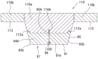
如果参照图3及图6,则帽90以帽底壁91的上表面91a与第1成形上表面111相接、帽侧壁92的内表面与第2成形上表面112相接、进而帽端面92a与阶差112a相接的方式被安装在上模110。此外,帽90以第1突条93嵌在第1槽部114并且第2突条94A~94E嵌在第2槽部115A~115E的方式被安装在上模110。即,帽90被配置为,将由第1成形上表面111及第2成形上表面112形成的角部118覆盖。在本实施方式中,帽90被固定在上模110,以将后述的腔室C(参照图12)的全部填埋。If referring to Fig. 3 and Fig. 6, then the
如果参照图6及图7,则在本实施方式中,帽90被用作为阳螺纹件的螺纹件150固定在上模110。具体而言,在第1突条93及第2突条94A~94E交叉的部分,设置有从帽底壁91的下表面91b朝向上模110贯通的贯通孔95A~95E。此外,在上模110,设置有被与贯通孔95A~95E对位的作为阴螺纹件的螺纹孔116A~116E。通过将螺纹件150经由贯通孔95A~95E紧固于螺纹孔116A~116E,将帽90固定在上模110。Referring to FIGS. 6 and 7 , in the present embodiment, the
此外,在贯通孔95A~95E的下表面91b侧设置有直径比贯通孔95A~95E大的锪孔96,在将螺纹件150紧固时,螺纹件150的头部被收纳在锪孔96内,以使得螺纹件150的头部不从帽底壁91的下表面91b突出。In addition, a
由于帽90被用螺纹件150固定在上模110,所以通过将螺纹件150拆下,能够将帽90从上模110拆下。即,帽90能够拆装地被固定在上模110。帽90既可以借助使用双面胶带等的粘接被固定在上模110,也可以借助从埋入于上模110的磁铁产生的磁力被固定。Since the
参照图9~图13,对本实施方式的用来制造金属树脂复合体1的方法进行说明。在图中,将水平方向表示为X方向,将铅直方向(上下方向)表示为Y方向。此外,对于金属树脂复合体1(金属板10和树脂材料20),赋予表示是截面的剖面线,而对于其他部件,为了使图示变得清楚而将剖面线省略。The method for manufacturing the metal-
在本实施方式中,在将图9~图13所示的第1~5工序依次执行的过程中执行两次加压成形。在图9~图11所示的第1~3工序中执行第1次加压成形,在图11~图13所示的第3~5工序中执行第2次加压成形。In the present embodiment, press molding is performed twice while sequentially performing the first to fifth steps shown in FIGS. 9 to 13 . The first press forming is performed in the first to third steps shown in FIGS. 9 to 11 , and the second press forming is performed in the third to fifth steps shown in FIGS. 11 to 13 .
在图9所示的第1工序中,在将帽90安装于上模110的状态下,将成形前的平板状的金属板10载置在下模120之上。In the first step shown in FIG. 9 , the
在图10所示的第2工序中,使上模110下降,将金属板10用安装有帽90的上模110和下模120夹入,加压成形为帽子形。此时,金属板10主要被第1加压面97朝向下模120推压。在上模110和下模120被闭合的状态下,帽底壁91的下表面91b与第1成形下表面121之间的距离d1大致等于金属板10的厚度t(d1=t)。通过将距离d1设定为相对于金属板10的厚度t相等,能够提高金属板10的成形精度。此外,第3成形上表面113与第3成形下表面123之间的距离d3大致等于金属板10的厚度t(d3=t)。此外,阶差112a的下方的帽侧壁92的外表面92b与第2成形下表面122之间的距离d21相对于金属板10的厚度t大致相等或稍大(d21=t或d21>t)。此外,阶差112a的上方的第2成形上表面112与第2成形下表面122之间的距离d22相对于金属板10的厚度t大致相等或稍大(d22=t或d22>t)。特别是,通过将距离d22设定为相对于金属板10的厚度t相等,能够提高后工序中的树脂材料20的填充压力。另外,在本工序中,树脂材料20(参照图11~图13)还没有被填充,仅将金属板10经由帽90用上模110和下模120夹入。In the second step shown in FIG. 10 , the
在图11所示的第3工序中,使上模110上升。此时,金属板10被成形为最终形状(在本实施方式中是帽子形)。然后,在金属板10上载置裁切为需要的尺寸的片状的树脂材料20(也称作预浸料坯(prepreg))。在本实施方式中,借助被称作SMC(Sheet MoldingCompound;片状模塑料)法的成形法,使该树脂材料20在高温高压下固化(参照后述的第4工序)。在本实施方式中,作为树脂材料20,使用使玻璃纤维、碳纤维浸渍于树脂而成的纤维强化树脂(FRP:Fiber Reinforced Plastic;纤维强化塑料)。此外,在本实施方式中,树脂材料20具有热固化性。在本工序中,树脂材料20还没有被加热,即没有固化。另外,树脂材料20不需要是片状,可以取任意的形状。In the third step shown in FIG. 11 , the
此外,在第3工序中,从上模110将帽90拆下。安装着帽90的状态下的第1加压面97与下模120之间的距离d1、d21(参照图10)比帽90被拆下的状态下的第2加压面117与下模120之间的距离d4、d5(参照图12)短。更具体地讲,距离d1比距离d4短,距离d21比距离d5短。在帽90被拆下后,将未图示的埋孔用螺纹件紧固于螺纹孔116A~116E而将螺纹孔116A~116E填埋,以使得树脂材料20不进入到上模110的螺纹孔116A~116E。In addition, in the third step, the
在图12所示的第4工序中,使上模110下降,将金属板10和树脂材料20用上模110和下模120夹入,进行加压成形,以使树脂材料20固接于金属板10。此时,金属板10及树脂材料20被第2加压面117朝向下模120推压。此外,在设置在第1~2成形上表面111~112与第1~2成形下表面121~122(详细地讲是金属板10)之间的腔室C填充树脂材料20。即,借助SMC法,将裁切为需要的尺寸的树脂材料20投入到金属模100,在高温高压下使其固化。在本实施方式中,腔室C是指被上模110和下模120(详细地讲是金属板10)夹入而形成的比阶差112a靠下方的空间和由第1槽部114及第2槽部115A~115E划定的空间。In the fourth step shown in FIG. 12 , the
当向腔室C填充树脂材料20时,树脂材料20也流入到上模110的第1槽部114及第2槽部115A~115E,成形出第1肋5及第2肋6A~6E(参照图1)。另外,在本实施方式中,帽90以将腔室C的全部填埋的方式配置,树脂材料20被填充到腔室C的全部。因此,如图1及图5所示,帽90和金属树脂复合体1的树脂材料20成为大致相等的形状。When the cavity C is filled with the
在图13所示的第5工序中,使上模110上升。在金属板10的上表面(帽子形的凹面)固接着树脂材料20,形成金属树脂复合体1。这样,制造出作为制品的帽子形的金属树脂复合体1。In the fifth step shown in FIG. 13 , the
在用1组金属模100进行金属板10的加压成形和金属板10及树脂材料20的一体成形的情况下,在上模110及下模120闭合的状态下形成配置树脂材料20的腔室C。因此,在金属板10的加压成形时,在形成有其腔室C的部位,上模110不能使金属板10沿着下模120的成形面的形状成形。相对于此,根据本实施方式,可以首先在将金属板10加压成形时将帽90安装于上模110,接着在将金属树脂复合体1加压成形时将帽90从上模110拆下。此外,安装着帽90的状态下的第1加压面97与下模120之间的距离d1、d21成为比帽90被拆下的状态下的第2加压面117与下模120之间的距离d4、d5短。即,由于在金属板10的加压成形时由帽90将腔室C的至少一部分填埋,所以腔室C减少,在金属板10的加压成形时,金属板10变得容易沿着下模120的形状。结果,能够提高金属板10的成形精度。而且,通过在将金属树脂复合体1加压成形时将帽90拆下,能够形成希望的大小及形状的腔室C,所以能够制造希望的形状的金属树脂复合体1。In the case of performing press molding of the
此外,在帽90被安装于上模110的状态下将上模110及下模120闭合的情况下,由于没有腔室C,所以在金属板10的加压成形时金属板10变得容易沿着下模120的形状。因此,能够提高金属板10的成形精度。In addition, when the
在第4工序中将树脂材料20填充时,树脂材料20为了从腔室C漏出需要越过上模110的阶差112a而流动,所以能够由阶差112a将腔室C封闭。因而,能够抑制树脂材料20的漏出。即,能够提高树脂材料20的腔室C中的填充压力,提高品质。When filling the
由于帽90被用螺纹件150固定在上模110,所以能够将帽90机械性地牢固地固定在上模110。因此,能够抑制或防止在加压成形时帽90从上模110脱离。Since the
在本实施方式的金属树脂复合体1中,由于成形出第1肋5及第2肋6A~6B,所以金属树脂复合体1的强度能够提高。In the metal-
(第2实施方式)(Second embodiment)
图14所示的第2实施方式在上模110没有设置第1槽部114(参照图4)及第2槽部115A~115E(参照图4)。此外,在帽90没有设置第1突条93(参照图5)及第2突条94A~94E(参照图5)。进而,在上模110埋入有磁铁160。关于这些以外,与第1实施方式实质上相同。因而,关于在第1实施方式中表示的部分有将说明省略的情况。In the second embodiment shown in FIG. 14 , the
在第2实施方式中,帽90是大致C字型的板状,仅具有帽底壁91及帽侧壁92。帽90通过对金属板实施弯曲加工而成形。另外,帽90的成形方法并不限定于弯曲加工,例如也可以借助切削来成形。In the second embodiment, the
在上模110埋入有磁铁160。因此,金属制的帽90借助磁力而被固定在上模110。A
在第2实施方式中,由于将帽90借助金属板的弯曲加工而成形,所以加工较容易。即,能够减少帽90的制造工时数。此外,由于将帽90借助磁铁160而固定在上模110,所以帽90的拆装较容易。In the second embodiment, since the
如果参照图15,则在第2实施方式的变形例中,在上模110,如第1实施方式所示那样设置有第1槽部114及第2槽部115A~115E(参照图4)。此外,在帽90没有设置第1突条93(参照图5)及第2突条94A~94E(参照图5)。Referring to FIG. 15 , in the modified example of the second embodiment, the
在该变形例中,对于第1实施方式所示的装接帽90的上模110也能够装接帽90。换言之,能够对共同的上模110装接不同形状的帽90。In this modified example, the
如果参照图16,则在第2实施方式的变形例中,帽90由角帽90a、90b构成。角帽90a、90b被能够拆装地固定,以将腔室C(参照图12)的一部分填埋。具体而言,角帽90a、90b被配置为,仅覆盖在由上模110的第1成形上表面111及第2成形上表面112形成的角部118。Referring to FIG. 16 , in a modified example of the second embodiment, the
通过构成为,帽90仅将腔室C的一部分填埋,帽90的重量被减少,帽90的拆装能够变得容易。By configuring the
此外,由于将帽90安装在由第1成形上表面111及第2成形上表面112形成的角部118,所以当在第2工序中将金属板10加压成形时,在角部118,距离d1(参照图10)及距离d21(参照图10)成为与金属板10的厚度t相等。换言之,角部118处的腔室C减少。在腔室C减少的部位,在金属板10的加压成形时金属板10变得容易沿着下模120的形状,所以金属板10的角部118处的成形精度能够提高。特别是,由于在角部118被要求成形精度,所以在角部118使腔室C减少来提高尺寸精度是有效的。此外,金属板10的不发生弯曲的直线部分通过在第4工序中与树脂材料20一起被加压成形,能够成为最终形状。因而,金属树脂复合体1的成形精度能够提高。In addition, since the
在金属树脂复合体1中,也可以在金属板10与树脂材料20之间设置粘接层。在此情况下,通过设置粘接层,能够将金属部件10和树脂材料20牢固地一体成形。In the metal-
附图标记说明Explanation of reference signs
1 金属树脂复合体1 Metal Resin Composite
2 底壁部2 bottom wall
3 侧壁部3 side wall
3a 阶差部3a step part
4 凸缘部4 Flange
5 第1肋5 1st rib
6A~6E 第2肋6A~6E 2nd rib
10 金属板(金属部件)10 sheet metal (metal parts)
20 树脂材料20 resin material
20a 端面20a end face
50 装置50 devices
80 金属模套件80 Metal Die Kit
90 帽(成形辅助零件)90 Caps (Forming Auxiliary Parts)
90a、90b 角帽90a, 90b horn hat
91 帽底壁91 cap bottom wall
91a 上表面91a upper surface
91b 下表面91b lower surface
92 帽侧壁92 cap side wall
92a 帽端面92a cap end face
92b 外表面92b External surface
93 第1突条93 1st protrusion
94A~94E 第2突条94A~94E 2nd protrusion
95A~95E 贯通孔95A~95E through hole
96 锪孔96 spot facing
97 第1加压面97 1st pressure surface
100 金属模100 metal molds
110 上模110 upper mold
110a 冲头110a Punch
110b 保持器110b retainer
111 第1成形上表面111 The first forming upper surface
112 第2成形上表面112 The second forming upper surface
112a 阶差112a Step difference
113 第3成形上表面113 The third forming upper surface
114 第1槽部114 1st slot part
115A~115E 第2槽部115A~115E 2nd slot part
116A~116E 螺纹孔116A~116E threaded hole
117 第2加压面117 Second pressure surface
118 角部118 Corner
120 下模120 lower mold
121 第1成形下表面121 1st forming lower surface
122 第2成形下表面122 Second forming lower surface
123 第3成形下表面123 3rd forming lower surface
130 驱动部130 drive unit
140 加热部140 heating part
150 螺纹件150 threaded parts
160 磁铁160 magnets
C 腔室。C Chamber.
Claims (7)
Applications Claiming Priority (2)
| Application Number | Priority Date | Filing Date | Title |
|---|---|---|---|
| JP2021-166372 | 2021-10-08 | ||
| JP2021166372A JP7560059B2 (en) | 2021-10-08 | 2021-10-08 | Apparatus, die set, and method for manufacturing metal-resin composite |
Publications (1)
| Publication Number | Publication Date |
|---|---|
| CN115958734A true CN115958734A (en) | 2023-04-14 |
Family
ID=84330657
Family Applications (1)
| Application Number | Title | Priority Date | Filing Date |
|---|---|---|---|
| CN202211206512.4A Pending CN115958734A (en) | 2021-10-08 | 2022-09-30 | Device, die set and method for manufacturing metal-resin composite |
Country Status (4)
| Country | Link |
|---|---|
| US (1) | US12059827B2 (en) |
| EP (1) | EP4163081A1 (en) |
| JP (1) | JP7560059B2 (en) |
| CN (1) | CN115958734A (en) |
Families Citing this family (2)
| Publication number | Priority date | Publication date | Assignee | Title |
|---|---|---|---|---|
| JP2025017051A (en) * | 2023-07-24 | 2025-02-05 | 株式会社神戸製鋼所 | Metal-resin composite and its manufacturing method |
| JP2025019842A (en) * | 2023-07-28 | 2025-02-07 | 株式会社神戸製鋼所 | Metal-resin composite and its manufacturing method |
Citations (3)
| Publication number | Priority date | Publication date | Assignee | Title |
|---|---|---|---|---|
| US4378265A (en) * | 1980-07-24 | 1983-03-29 | Lignotock Verfahrenstechnik Gmbh | Process for producing molded parts from flat tangled fleece mats |
| WO2015192515A1 (en) * | 2014-06-20 | 2015-12-23 | 黄欣 | Integrated molding device for silica gel and sheet steel in sealing gasket of tablet computer |
| CN110065191A (en) * | 2018-01-22 | 2019-07-30 | 东和株式会社 | The manufacturing method of shaping mould, resin molding apparatus and synthetic resin |
Family Cites Families (13)
| Publication number | Priority date | Publication date | Assignee | Title |
|---|---|---|---|---|
| US20040096535A1 (en) * | 2002-11-15 | 2004-05-20 | Hudecek Robert W. | Compression molding apparatus having replaceable mold inserts |
| JP4540049B2 (en) * | 2004-09-28 | 2010-09-08 | 大和製罐株式会社 | Method for manufacturing metal cap with sealing liner |
| DE102011050701A1 (en) * | 2011-05-30 | 2012-12-06 | Benteler Automobiltechnik Gmbh | Method for producing a hybrid component and cover for use in the manufacture |
| JP5919066B2 (en) | 2012-03-30 | 2016-05-18 | 富士重工業株式会社 | Monolithic molded part manufacturing method and monolithic molded part |
| CN105073389B (en) * | 2013-03-13 | 2018-04-03 | 爱信高丘株式会社 | Composite structure of fiber-reinforced plastic plate and metal plate and manufacturing method thereof |
| DE102013109616A1 (en) * | 2013-09-03 | 2015-03-05 | Thyssenkrupp Steel Europe Ag | Semi-finished product and method for producing a three-dimensionally shaped hybrid component in the metal / plastic composite and use of such a semi-finished product |
| WO2015034119A1 (en) | 2013-09-09 | 2015-03-12 | Lee Hwan Gil | Injection molding method, injection mold, and material injected by same |
| EP2886287A1 (en) * | 2013-12-20 | 2015-06-24 | nolax AG | Method for producing hybrid components |
| JP6303053B1 (en) * | 2017-07-26 | 2018-03-28 | 株式会社The MOT Company | Method for producing metal-fiber reinforced resin composite molded body |
| CN112203822B (en) * | 2018-05-24 | 2022-10-04 | 日产自动车株式会社 | Method for molding part using resin-metal composite, and mold for molding the part |
| JP7093299B2 (en) | 2018-12-27 | 2022-06-29 | 豊田鉄工株式会社 | Hot press equipment and metal resin composite molding method |
| JP7249932B2 (en) * | 2019-12-10 | 2023-03-31 | 豊田鉄工株式会社 | Heat press device and molding method for metal-resin composite |
| JP2022189011A (en) * | 2021-06-10 | 2022-12-22 | 株式会社神戸製鋼所 | Mold, apparatus and method for manufacturing metal-resin composite |
-
2021
- 2021-10-08 JP JP2021166372A patent/JP7560059B2/en active Active
-
2022
- 2022-09-22 US US17/934,384 patent/US12059827B2/en active Active
- 2022-09-30 CN CN202211206512.4A patent/CN115958734A/en active Pending
- 2022-10-05 EP EP22199850.3A patent/EP4163081A1/en active Pending
Patent Citations (3)
| Publication number | Priority date | Publication date | Assignee | Title |
|---|---|---|---|---|
| US4378265A (en) * | 1980-07-24 | 1983-03-29 | Lignotock Verfahrenstechnik Gmbh | Process for producing molded parts from flat tangled fleece mats |
| WO2015192515A1 (en) * | 2014-06-20 | 2015-12-23 | 黄欣 | Integrated molding device for silica gel and sheet steel in sealing gasket of tablet computer |
| CN110065191A (en) * | 2018-01-22 | 2019-07-30 | 东和株式会社 | The manufacturing method of shaping mould, resin molding apparatus and synthetic resin |
Also Published As
| Publication number | Publication date |
|---|---|
| EP4163081A1 (en) | 2023-04-12 |
| US20230111000A1 (en) | 2023-04-13 |
| JP2023056889A (en) | 2023-04-20 |
| US12059827B2 (en) | 2024-08-13 |
| JP7560059B2 (en) | 2024-10-02 |
Similar Documents
| Publication | Publication Date | Title |
|---|---|---|
| CN115958734A (en) | Device, die set and method for manufacturing metal-resin composite | |
| CN114269548A (en) | Method and device for producing a component made of a fiber composite material | |
| CN106042419A (en) | Press molding apparatus and press molding method | |
| CN105269718A (en) | Method and device for manufacturing automotive resin part | |
| CN108778661A (en) | FRP stamped from sheetstock forming method and device and FRP molded products | |
| TWI610801B (en) | Manufacturing apparatus and manufacturing method of resin molded article | |
| CN115464825A (en) | Mold, apparatus and method for manufacturing metal-resin composite | |
| CN108136685A (en) | The manufacturing method of fiber-reinforced resin works, the manufacture system of fiber-reinforced resin works and fiber-reinforced resin works | |
| CN217097927U (en) | Integrated device for realizing cutting and surface treatment | |
| CN115464824A (en) | Metal mold, device and method for manufacturing metal-resin composite | |
| CN116890451B (en) | Method for manufacturing metal-resin composites | |
| JP7542490B2 (en) | Apparatus and method for manufacturing metal-resin composites | |
| US9579853B2 (en) | Method for making a molded composite article | |
| JP5967014B2 (en) | Method for manufacturing molded structure | |
| JPS581518A (en) | Preparation of vacuum molded parts | |
| JP2020142457A (en) | A method for manufacturing a fiber-reinforced resin molded product and a molding die used for the manufacturing method. | |
| JP7755551B2 (en) | Metal-resin composite and method and apparatus for manufacturing the same | |
| EP4063107B1 (en) | Fiber reinforced composite material molding method and system comprising a fiber reinforced composite material molding apparatus and fiber base material. | |
| JP2023156888A (en) | Apparatus and method for manufacturing metal-resin composite | |
| JP5247733B2 (en) | Plastic molded product | |
| JP2023156887A (en) | Apparatus and method for manufacturing metal-resin composite | |
| CN117324502A (en) | Metal-resin composite body, and method and apparatus for producing metal-resin composite body | |
| CN108778660B (en) | FRP sheet compression molding method and apparatus and FRP molded product | |
| EP4108431A1 (en) | A method for producing a thermoplastic composite component | |
| JP2022189013A (en) | Apparatus and method for manufacturing metal-resin composite |
Legal Events
| Date | Code | Title | Description |
|---|---|---|---|
| PB01 | Publication | ||
| PB01 | Publication | ||
| SE01 | Entry into force of request for substantive examination | ||
| SE01 | Entry into force of request for substantive examination |