CN115868687A - Gas mist generating device and heater for gas mist generating device - Google Patents
Gas mist generating device and heater for gas mist generating device Download PDFInfo
- Publication number
- CN115868687A CN115868687A CN202111154405.7A CN202111154405A CN115868687A CN 115868687 A CN115868687 A CN 115868687A CN 202111154405 A CN202111154405 A CN 202111154405A CN 115868687 A CN115868687 A CN 115868687A
- Authority
- CN
- China
- Prior art keywords
- aerosol
- heater
- generating device
- temperature sensor
- section
- Prior art date
- Legal status (The legal status is an assumption and is not a legal conclusion. Google has not performed a legal analysis and makes no representation as to the accuracy of the status listed.)
- Pending
Links
Images


Classifications
-
- A—HUMAN NECESSITIES
- A24—TOBACCO; CIGARS; CIGARETTES; SIMULATED SMOKING DEVICES; SMOKERS' REQUISITES
- A24F—SMOKERS' REQUISITES; MATCH BOXES; SIMULATED SMOKING DEVICES
- A24F40/00—Electrically operated smoking devices; Component parts thereof; Manufacture thereof; Maintenance or testing thereof; Charging means specially adapted therefor
- A24F40/40—Constructional details, e.g. connection of cartridges and battery parts
- A24F40/46—Shape or structure of electric heating means
-
- A—HUMAN NECESSITIES
- A24—TOBACCO; CIGARS; CIGARETTES; SIMULATED SMOKING DEVICES; SMOKERS' REQUISITES
- A24F—SMOKERS' REQUISITES; MATCH BOXES; SIMULATED SMOKING DEVICES
- A24F40/00—Electrically operated smoking devices; Component parts thereof; Manufacture thereof; Maintenance or testing thereof; Charging means specially adapted therefor
- A24F40/50—Control or monitoring
- A24F40/51—Arrangement of sensors
-
- A—HUMAN NECESSITIES
- A24—TOBACCO; CIGARS; CIGARETTES; SIMULATED SMOKING DEVICES; SMOKERS' REQUISITES
- A24F—SMOKERS' REQUISITES; MATCH BOXES; SIMULATED SMOKING DEVICES
- A24F40/00—Electrically operated smoking devices; Component parts thereof; Manufacture thereof; Maintenance or testing thereof; Charging means specially adapted therefor
- A24F40/50—Control or monitoring
- A24F40/53—Monitoring, e.g. fault detection
Landscapes
- Resistance Heating (AREA)
Abstract
本申请提出一种气雾生成装置及用于气雾生成装置的加热器;其中,气雾生成装置包括:加热器,用于加热气溶胶生成制品;加热器具有第一区段和第二区段;其中,第二区段是主要用于加热气溶胶生成制品的加热区域,第一区段位于第二区段上游;电路,被编程为监测第一区段的温度变化,以检测表示使用者吸入的、经过加热器的气流的变化。以上气雾生成装置,通过监测第一区段的温度变化确定用户的抽吸动作。

The present application proposes an aerosol generating device and a heater for the aerosol generating device; wherein the aerosol generating device includes: a heater for heating an aerosol generating product; the heater has a first section and a second section section; wherein the second section is a heating zone mainly used to heat the aerosol-generating article, the first section is located upstream of the second section; the circuit is programmed to monitor the temperature change of the first section to detect the use of The change in the airflow drawn by the heater through the heater. The above aerosol generating device determines the user's inhalation action by monitoring the temperature change of the first section.
Description
技术领域technical field
本申请实施例涉及加热不燃烧烟具技术领域,尤其涉及一种气雾生成装置及用于气雾生成装置的加热器。The embodiments of the present application relate to the technical field of heat-not-burn smoking appliances, and in particular to an aerosol generating device and a heater used in the aerosol generating device.
背景技术Background technique
烟制品(例如,香烟、雪茄等)在使用过程中燃烧烟草以产生烟草烟雾。人们试图通过制造在不燃烧的情况下释放化合物的产品来替代这些燃烧烟草的制品。Smoking articles (eg, cigarettes, cigars, etc.) burn tobacco during use to produce tobacco smoke. Attempts have been made to replace these tobacco-burning products by making products that release compounds without burning them.
此类产品的示例为加热装置,其通过加热而不是燃烧材料来释放化合物。例如,该材料可为烟草或其他非烟草产品,这些非烟草产品可包含或可不包含尼古丁。作为已知的加热装置,CN201280060087.0号专利提出一种采用通过检测功率变化监测用户抽吸过程中的气流变化,进而根据该气流变化确定用户的抽吸动作。An example of such a product is a heating device, which releases a compound by heating rather than burning a material. For example, the material may be tobacco or other non-tobacco products, which may or may not contain nicotine. As a known heating device, Patent No. CN201280060087.0 proposes a method of monitoring the airflow change during the user's puffing process by detecting the power change, and then determining the user's puffing action according to the airflow change.
发明内容Contents of the invention
本申请的实施例提供一种气雾生成装置,用于加热气溶胶生成制品生成气溶胶;包括:An embodiment of the present application provides an aerosol generating device for heating an aerosol generating product to generate an aerosol; comprising:
加热器,用于加热气溶胶生成制品;所述加热器具有第一区段和第二区段;其中,所述第二区段是主要用于加热气溶胶生成制品的加热区域,所述第一区段位于所述第二区段上游;A heater for heating the aerosol-generating article; the heater has a first section and a second section; wherein the second section is a heating area mainly used for heating the aerosol-generating article, and the first a section upstream of the second section;
电路,被编程为监测所述第一区段的温度变化,以检测表示使用者吸入的、经过所述加热器的气流的变化。A circuit programmed to monitor changes in temperature of the first section to detect changes in airflow past the heater indicative of user inhalation.
在本文中,“上游”和“下游”相对位置是基于用户抽吸气溶胶生成制品时流经气雾生成装置的气流流动方向描述的。具体在气雾生成装置中,“上游”和“下游”相对位置是相对于气流被从空气入口端抽吸到空气出口端时的方向描述的;同样可以理解地在用户抽吸时,“下游”是气流靠近用户的嘴唇进而被吸入的一侧,“上游”是气流背离用户嘴唇的一侧。As used herein, the relative positions of "upstream" and "downstream" are described based on the direction of air flow through the aerosol-generating device when the user inhales the aerosol-generating article. Specifically in an aerosol generating device, the relative positions of "upstream" and "downstream" are described relative to the direction in which the airflow is drawn from the air inlet end to the air outlet end; ” is the side of the airflow close to the user’s lips where it is drawn in, and “upstream” is the side of the airflow away from the user’s lips.
在更加优选的实施中,所述电路被编程为监测所述第一区段的温度与预设值之差,以检测表示使用者吸入的、经过所述加热器的气流的变化。In a more preferred implementation, the circuitry is programmed to monitor the temperature of the first zone as a difference from a preset value to detect a change in airflow past the heater indicative of inhalation by the user.
在更加优选的实施中,所述电路被编程为监测所述第一区段的温度比预设值下降介于10℃~100℃时,以检测表示使用者吸入的、经过所述加热器的气流的变化。In a more preferred implementation, the circuit is programmed to monitor when the temperature of the first zone drops by 10°C to 100°C from a preset value, so as to detect the air that is inhaled by the user and passes through the heater. changes in airflow.
在更加优选的实施中,还包括:In a more preferred implementation, it also includes:
气流通道,至少部分界定使用者吸入时依次流经所述第一区段和第二区段的气流路径。The airflow channel at least partially defines the airflow path that flows sequentially through the first section and the second section when the user inhales.
在更加优选的实施中,还包括:腔室,具有沿轴向相对的第一端和第二端;在使用中,气溶胶生成制品能通过所述第一端至少部分接收于所述腔室;In a more preferred implementation, further comprising: a chamber having axially opposite first and second ends; in use, an aerosol-generating article is at least partially receivable in said chamber through said first end ;
所述第一区段比所述第二区段更靠近所述腔室的第二端。The first section is closer to the second end of the chamber than the second section.
在更加优选的实施中,所述加热器上设置有用于感测所述第一区段温度的第一温度传感器;In a more preferred implementation, the heater is provided with a first temperature sensor for sensing the temperature of the first section;
所述电路通过所述第一温度传感器监测所述第一区段的温度变化。The circuit monitors the temperature change of the first section through the first temperature sensor.
在更加优选的实施中,所述第一温度传感器包括连接于所述第一区段的第一电偶丝和第二电偶丝。In a more preferred implementation, the first temperature sensor includes a first galvanic wire and a second galvanic wire connected to the first section.
在更加优选的实施中,所述第一温度传感器是裸露于所述加热器外表面的。In a more preferred implementation, the first temperature sensor is exposed on the outer surface of the heater.
在更加优选的实施中,所述第一区段表面设置有凹陷区域,所述第一温度传感器至少部分位于所述凹陷区域内。In a more preferred implementation, a recessed area is provided on the surface of the first section, and the first temperature sensor is at least partially located in the recessed area.
在更加优选的实施中,所述加热器还包括基座,气雾生成装置通过该基座对所述加热器提供保持。In a more preferred implementation, the heater further includes a base, and the aerosol generating device provides support for the heater through the base.
在更加优选的实施中,所述第一温度传感器贯穿所述基座。In a more preferred implementation, the first temperature sensor runs through the base.
在更加优选的实施中,所述加热器还设有用于感测所述第二区段温度的第二温度传感器。In a more preferred implementation, the heater is further provided with a second temperature sensor for sensing the temperature of the second section.
在更加优选的实施中,所述加热器具有轴向延伸的中空;所述第二温度传感器至少部分被容纳于所述中空内。In a more preferred implementation, the heater has an axially extending hollow; the second temperature sensor is at least partially accommodated in the hollow.
在更加优选的实施中,所述第二温度传感器包括形成于所述第二区段的导电轨迹。In a more preferred implementation, the second temperature sensor comprises a conductive trace formed in the second section.
在更加优选的实施中,所述第一区段具有小于所述第二区段的延伸长度。In a more preferred implementation, said first section has an extension length which is smaller than said second section.
在更加优选的实施中,所述加热器具有用于插入至气溶胶生成制品内的自由前端、以及与所述自由前端相对的末端;所述第一区段靠近所述末端。In a more preferred implementation, said heater has a free front end for insertion into an aerosol generating article, and an end opposite said free front end; said first section being adjacent to said end.
在更加优选的实施中,所述第一区段由所述末端朝自由前端的延伸长度介于2~8mm。In a more preferred implementation, the extension length of the first section from the end to the free front end is 2-8 mm.
在更加优选的实施中,所述加热器是被变化的磁场穿透而发热的感受加热器;所述加热器包括有:In a more preferred implementation, the heater is a sensory heater that is penetrated by a changing magnetic field and generates heat; the heater includes:
沿长度方向布置的第一感受部分和第二感受部分,所述第一感受部分与第二感受部分可拆卸连接。A first sensing part and a second sensing part arranged along the length direction, the first sensing part and the second sensing part are detachably connected.
在更加优选的实施中,所述加热器具有用于插入至气溶胶生成制品内的自由前端、以及与所述自由前端相背的末端;所述第一感受部分界定所述自由前端、所述第二感受部分界定所述末端。In a more preferred implementation, the heater has a free front for insertion into an aerosol generating article, and an end opposite to the free front; the first sensing portion defines the free front, the second Two sensory moieties define the terminus.
在更加优选的实施中,所述第一温度传感器连接于所述第二感受部分靠近所述末端的部位。In a more preferred implementation, the first temperature sensor is connected to a portion of the second sensing portion close to the end.
在更加优选的实施中,所述第二感受部分具有毗邻所述第一感受部分的上端;In a more preferred implementation, the second sensing portion has an upper end adjacent to the first sensing portion;
所述加热器上设置有第二温度传感器;该第二温度传感器连接于所述上端。The heater is provided with a second temperature sensor; the second temperature sensor is connected to the upper end.
在更加优选的实施中,所述第二温度传感器沿所述第二感受部分的轴向贯穿所述第二感受部分。In a more preferred implementation, the second temperature sensor penetrates through the second sensing portion along the axial direction of the second sensing portion.
在更加优选的实施中,所述第二区段是主要用于加热气溶胶生成制品的加热区域。In a more preferred implementation, said second section is a heating zone primarily for heating the aerosol-generating article.
本申请的又一个实施例还提出一种气雾生成装置,用于加热气溶胶生成制品生成气溶胶;包括:Yet another embodiment of the present application also proposes an aerosol generating device for heating an aerosol generating product to generate an aerosol; comprising:
加热器,用于加热气溶胶生成制品;所述加热器具有依次布置的第一区段和第二区段,在使用者吸入时空气依次流经所述第一区段和第二区段;a heater for heating the aerosol-generating article; the heater has a first section and a second section arranged in sequence, and air flows through the first section and the second section sequentially when the user inhales;
电路,被编程为监测所述第一区段的温度变化,以检测表示使用者吸入的、经过所述加热器的气流的变化。A circuit programmed to monitor changes in temperature of the first section to detect changes in airflow past the heater indicative of user inhalation.
本申请的又一个实施例还提出一种气雾生成装置,用于加热气溶胶生成制品生成气溶胶;包括:Yet another embodiment of the present application also proposes an aerosol generating device for heating an aerosol generating product to generate an aerosol; comprising:
加热器,用于加热气溶胶生成制品;所述加热器具有相对的前端和末端;所述加热器上间隔布置有第一温度传感器和第二温度传感器,所述第一温度传感器比所述第二温度传感器更靠近所述末端;a heater for heating an aerosol-generating product; the heater has an opposite front end and an end; a first temperature sensor and a second temperature sensor are arranged at intervals on the heater, and the first temperature sensor is higher than the first temperature sensor a second temperature sensor closer to the end;
电路,被编程为监测所述第一温度传感器感测的温度变化,以检测表示使用者吸入的、经过所述加热器的气流的变化。A circuit programmed to monitor changes in temperature sensed by the first temperature sensor to detect changes in airflow past the heater indicative of user inhalation.
本申请的又一个实施例还提出一种气雾生成装置,用于加热气溶胶生成制品生成气溶胶;包括:Yet another embodiment of the present application also proposes an aerosol generating device for heating an aerosol generating product to generate an aerosol; comprising:
腔室,具有相对的第一端和第二端,并在所述第一端处形成开口;在使用中,气溶胶生成制品能通过所述开口由所述第一端接收至所述腔室内;a chamber having opposing first and second ends and forming an opening at said first end; in use, an aerosol-generating article is receivable into said chamber from said first end through said opening ;
加热器,至少部分于所述腔室内延伸,用于加热气溶胶生成制品;a heater extending at least partially within the chamber for heating the aerosol-generating article;
温度传感器,位于所述腔室内并靠近所述第二端布置;该温度传感器结合于所述加热器上;a temperature sensor, located in the chamber and arranged near the second end; the temperature sensor is combined with the heater;
电路,被编程为监测所述温度传感器感测的温度变化,以检测表示使用者吸入的、经过所述加热器的气流的变化。A circuit programmed to monitor changes in temperature sensed by the temperature sensor to detect changes in air flow past the heater indicative of user inhalation.
本申请的又一个实施例还提出一种用于气雾生成装置的加热器,所述加热器包括具有沿长度方向的前端和末端;所述加热器上设置有:Another embodiment of the present application also proposes a heater for an aerosol generating device, the heater includes a front end and an end along the length direction; the heater is provided with:
第一温度传感器和第二温度传感器,所述第一温度传感器比所述第二温度传感器更靠近所述末端。A first temperature sensor and a second temperature sensor, the first temperature sensor being closer to the end than the second temperature sensor.
以上气雾生成装置,通过监测第一区段的温度变化确定用户的抽吸动作。The above aerosol generating device determines the user's inhalation action by monitoring the temperature change of the first section.
附图说明Description of drawings
一个或多个实施例通过与之对应的附图中的图片进行示例性说明,这些示例性说明并不构成对实施例的限定,附图中具有相同参考数字标号的元件表示为类似的元件,除非有特别申明,附图中的图不构成比例限制。One or more embodiments are exemplified by the pictures in the corresponding drawings, and these exemplifications do not constitute a limitation to the embodiments. Elements with the same reference numerals in the drawings represent similar elements. Unless otherwise stated, the drawings in the drawings are not limited to scale.
图1是本申请一实施例提供的气雾生成装置的示意图;Fig. 1 is a schematic diagram of an aerosol generating device provided by an embodiment of the present application;
图2是图1中加热器又一个视角的结构示意图;Fig. 2 is a structural schematic diagram of another viewing angle of the heater in Fig. 1;
图3是图2中加热器一个视角的剖面示意图;Fig. 3 is a schematic cross-sectional view of a viewing angle of the heater in Fig. 2;
图4是图2中加热器一个视角的分解示意图;Fig. 4 is an exploded schematic diagram of a viewing angle of the heater in Fig. 2;
图5是图4中第一部分又一个视角的剖面示意图;Fig. 5 is a schematic cross-sectional view of another viewing angle of the first part in Fig. 4;
图6是又一个实施例提供的气雾生成装置的结构示意图;Fig. 6 is a schematic structural diagram of an aerosol generating device provided by another embodiment;
图7是图6中加热器又一个视角的结构示意图;Fig. 7 is a structural schematic diagram of another viewing angle of the heater in Fig. 6;
图8是又一个实施例提供的加热器的结构示意图;Fig. 8 is a schematic structural view of a heater provided in yet another embodiment;
图9是又一个实施例提供的加热器的结构示意图;Fig. 9 is a schematic structural view of a heater provided in yet another embodiment;
图10是又一个实施例提供的加热器的结构示意图。Fig. 10 is a schematic structural diagram of a heater provided in yet another embodiment.
具体实施方式Detailed ways
为了便于理解本申请,下面结合附图和具体实施方式,对本申请进行更详细的说明。In order to facilitate the understanding of the present application, the present application will be described in more detail below in conjunction with the accompanying drawings and specific implementation methods.
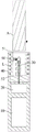
本申请的一实施例提出一种气雾生成装置,其构造可以参见图1所示,包括:An embodiment of the present application proposes an aerosol generating device, the structure of which can be seen in Figure 1, including:
腔室50,气溶胶生成制品A可移除地接收在腔室50内;a
磁场发生器,例如电感线圈L,用于在交变电流下产生变化磁场;A magnetic field generator, such as an induction coil L, for generating a changing magnetic field under an alternating current;
加热器30,至少一部分在腔室内延伸,并被配置为与电感线圈L感应耦合,在被变化磁场穿透下发热,进而对气溶胶生成制品A例如烟支进行加热,使气溶胶生成制品A的至少一种成分挥发,形成供抽吸的气溶胶;The
电芯10,为可充电的直流电芯,可以输出直流电流;The
电路20,通过适当的电连接到可充电的电芯10,用于从将电芯10输出的直流电流,转变成具有适合频率的交变电流再供应到电感线圈L。The
具体,进一步参见图1所示,腔室50具有位于相对的第一端51和第二端52。其中,腔室50的第一端51为敞口,腔室50的第二端52基本是封闭的;在使用中气溶胶生成制品A通过第一端51的敞口可移除地接收于腔室50,并且在接收于腔室50内时基本是抵靠在腔室50的第二端52形成止动的。同时在该实施中,气溶胶生成制品A接收至腔室50内时,加热器30插入至气溶胶生成制品A内进行加热。Specifically, referring further to FIG. 1 , the
根据产品使用中的设置,电感线圈L可以包括绕成螺旋状的圆柱形电感器线圈,如图1中所示。绕成螺旋状的圆柱形电感线圈L可以具有范围在大约5mm到大约10mm内的半径r,并特别地半径r可以大约为7mm。绕成螺旋状的圆柱形电感线圈L的长度可以在大约8mm到大约14mm的范围内,电感线圈L的匝数大约8匝到15匝的范围内。相应地,内体积可能在大约0.15cm3至大约1.10cm3的范围内。According to the setting in use of the product, the inductor coil L may include a cylindrical inductor coil wound in a helical shape, as shown in FIG. 1 . The helically wound cylindrical inductor L may have a radius r in the range of about 5 mm to about 10 mm, and in particular the radius r may be about 7 mm. The length of the helically wound cylindrical inductor L may range from about 8 mm to about 14 mm, and the number of turns of the inductor L may range from about 8 turns to 15 turns. Accordingly, the internal volume may be in the range of about 0.15 cm 3 to about 1.10 cm 3 .
在更加优选的实施中,电路20供应到电感线圈L的交变电流的频率介于80KHz~400KHz;更具体地,所述频率可以在大约200KHz到300KHz的范围。In a more preferred implementation, the frequency of the alternating current supplied by the
在一个优选的实施例中,电芯10提供的直流供电电压在约2.5V至约9.0V的范围内,电芯10可提供的直流电流的安培数在约2.5A至约20A的范围内。In a preferred embodiment, the DC power supply voltage provided by the
在一个优选的实施例中,加热器30大体呈销钉或针状或棒状或柱状或者刀片状的形状,进而对于插入至气溶胶生成制品A内是有利的;同时,加热器30可以具有大约12毫米的长度,大约4毫米的宽度和大约0.5毫米的厚度,并且可以由等级430的不锈钢(SS430)制成。作为替代性实施例,加热器30可以具有大约12毫米的长度,大约5毫米的宽度和大约0.5毫米的厚度,并且可以由等级430的不锈钢(SS430)制成。在其他的变化实施例中,加热器30还可以被构造成圆筒状的形状;在使用时其内部空间用于接收气溶胶生成制品A,并通过对气溶胶生成制品A的外周加热的方式,生成供吸食的气溶胶。加热器30还可以由等级420的不锈钢(SS420)、以及含有铁镍的合金材料(比如坡莫合金)制成。In a preferred embodiment, the
在图1所示的实施例中,气雾生成装置还包括用于布置电感线圈L和/或加热器30的支架40,该支架40的材质可以包括耐高温非金属材料比如PEEK或者陶瓷等。在实施中,电感线圈L采用缠绕在支架40的外壁上进而固定。同时,根据图1所示,该支架40的中空的管状形状,其管状中空的部分空间形成上述用于接收气溶胶生成制品A的腔室50。In the embodiment shown in FIG. 1 , the aerosol generating device further includes a
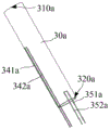
在一个优选的实施方式中,加热器30的细节构造上参见图2至图4所示,大概是被构造成细长的销钉或针状或棒状或柱状;包括沿长度方向相对的前端310和末端320;根据图1所示,前端310是延伸至腔室50内的自由端,并且构造成尖端的形状,便于插入至气溶胶生成制品A内。In a preferred embodiment, the detailed structure of the
在使用中,参见图2所示,加热器30基本包括有第一区段S1和第二区段S2;在实施中第二区段S2是主要插入至气溶胶生成制品A内进行加热的区段;通常在工作中,第二区段S2加热温度被保持在280~320℃,是主要的高温加热区域。而第一区段S1靠近末端320,由于远离中心,则使用中该区段部位的温度通常相比加热器30的最高温度区域低大约50~80℃。In use, as shown in FIG. 2, the
并且在抽吸中,气流如图中箭头R所示,依次流经第一区段S1和第二区段S2后直至被用户吸食。由于第一区段S1远离中心为非高温区段,并且抽吸中冷空气先流经该第一区段S1,在抽吸时对该区段热量交换较大使该区段的温度下降较为显著;而后空气继续流经第二区段S2时已经具有一定的温度,使第二区段S2的温度下降相对更少进而基本是不明显的。则在实施中,通过监测第一区段S1温度的明显变化,即可用于确定用户的抽吸动作。And during the suction, the airflow, as shown by the arrow R in the figure, flows through the first section S1 and the second section S2 in sequence until it is inhaled by the user. Since the first section S1 is far away from the center and is a non-high-temperature section, and the cold air flows through the first section S1 first during suction, the heat exchange to this section is relatively large during suction, so that the temperature drop in this section is more significant ; Then, when the air continues to flow through the second section S2, it already has a certain temperature, so that the temperature drop of the second section S2 is relatively less and basically insignificant. Then in practice, by monitoring the obvious change of the temperature of the first section S1, it can be used to determine the user's puffing action.
具体的温度感测和相适配的加热器30的结构在一个实施例中参见图2至图4所示,该实施例中加热器30包括:The specific temperature sensing and matching structure of the
沿长度方向依次布置的第一感受部分31和第二感受部分32;其中,第一感受部分31靠近前端310、第二感受部分32靠近末端320。The
在优选的实施中,第一感受部分31和第二感受部分32是可拆卸连接的。以及在优选的实施中,第一感受部分31和第二感受部分32的表面是平整接合的。In a preferred implementation, the
在图2和图3所示的优选的实施中,装配后由第一感受部分31具有外径逐渐减小的锥形区段311,并由该外径逐渐减小的锥形区段311界定前端310;以及,在图2和图3所示的优选的实施中以及由第二感受部分32形成末端320。In the preferred implementation shown in FIGS. 2 and 3 , after assembly, the
根据图2和图3所示,第二感受部分32在末端320处具有沿径向向外延伸出的基座321,在装配中气雾生成装置或支架40通过夹持或固定该基座321进而使加热器30稳定保持在气雾生成装置内。进而在装配后,第二感受部分32是被固定和保持在气雾生成装置内的,第一感受部分31是能够被拆卸或移除的。2 and 3, the
进一步参见图3至图5所示,第一感受部分31具有沿轴向延伸的第一中空312;当然该第一中空312具有背离前端310的敞口。在装配后,第二感受部分32至少部分延伸至第一中空312内。在图5中所示,该第一中空312的内壁上设置有内螺纹313。Referring further to FIG. 3 to FIG. 5 , the
进一步参见图4所示,第二感受部分32具有连接部分323,该连接部分323具有小于其他部分的外径;以及,该连接部分323上设置有外螺纹324。进而在装配中,该连接部分323伸入至第一感受部分31的第一中空312内、并通过内螺纹313与外螺纹324的配合使第一感受部分31和第二感受部分32稳定的可拆卸连接。Referring further to FIG. 4 , the
当然在装配后,第一感受部分31和第二感受部分32彼此是相互导热的。Of course, after assembly, the
进一步在优选的实施中,内螺纹313和/或外螺纹324采用左旋螺纹,即内螺纹313和/或外螺纹324的螺旋方向是逆时针方向。采用左旋螺纹对在使用或震动中防止内螺纹313和外螺纹324之间松脱是有利的。Further in a preferred implementation, the
进一步在优选的实施中,内螺纹313和/或外螺纹324的螺纹圈数可以采用1~20圈;更加优选地,内螺纹313和/或外螺纹324的螺纹圈数为2~8圈。Further in a preferred implementation, the number of turns of the
进一步参见图3和图4所示,第二感受部分32具有沿轴向贯穿的第二中空322。加热器30还包括有第一电偶丝引脚341和第二电偶丝引脚342,该第一电偶丝引脚341和第二电偶丝引脚342通过焊接例如激光焊、电阻焊或氩弧焊等方式连接于第二感受部分32的上端,并且分别采用不同的电偶材质,进而在它们之间形成可以用于测温的热电偶。在装配后,连接于第二感受部分32上端的第一电偶丝引脚341和第二电偶丝引脚342是与第一感受部分31的第一中空312的内顶壁接触的。Referring further to FIG. 3 and FIG. 4 , the
在更加优选的实施中,第一电偶丝331和第二电偶丝332由第二感受部分32贯穿第二中空322至末端320外,以便于与电路20连接。In a more preferred implementation, the first galvanic wire 331 and the second galvanic wire 332 pass through the second hollow 322 from the
在实施中,第二感受部分32的延伸长度大约在8~15mm;第一感受部分大约3~8mm;第一感受部分31的第一中空312大约具有3~5mm的延伸长度。在装配后,第一电偶丝331和第二电偶丝332连接于第二感受部分32的位置,基本是处于加热器30工作中温场的最高温度区域位置;则第一电偶丝331和第二电偶丝332形成的热电偶基本是用于检测加热器30工作中温场的最高温度区域的温度。In practice, the extension length of the
进一步参见图2和图4所示,在更加优选的实施中,加热器30的第二感受部分32外表面上设置有靠近基座321/末端320的凹陷区域325。该凹陷区域325内通过焊接例如激光焊、电阻焊或氩弧焊等方式连接有第三电偶丝引脚351和第四电偶丝引脚352;当然,第三电偶丝引脚351和第四电偶丝引脚352它们采用不同的电偶材质,则在它们之间形成用于感测温度的热电偶。Further referring to FIG. 2 and FIG. 4 , in a more preferred implementation, a recessed
进一步参见图1和图2所示,在用户抽吸气溶胶生成制品A的过程中,抽吸气流是由腔室50的第二端52穿过气溶胶生成制品A后被用户吸食,如图1和图2中箭头R所示。而加热器30插入至气溶胶生成制品A内,则在抽吸的过程中,抽吸气流会流经加热器30的表面。并且在用户抽吸时,第二感受部分32的凹陷区域325靠近腔室50的第二端52,冷空气由该部分进入并流经凹陷区域325时,通过热量交换能使凹陷区域325表面的温度下降,而通过采样第三电偶丝引脚351和第四电偶丝引脚352之间形成的热电偶的温度感测信号,通过温度的变化即可确定用户的抽吸动作。Further referring to FIG. 1 and FIG. 2, in the process of the user inhaling the aerosol generating product A, the suction air flow is inhaled by the user after passing through the aerosol generating product A through the
在又一个优选的实施中,通常在实施中加热器30的加热温度被保持在280~320℃,在工作中第一电偶丝331和第二电偶丝332形成的热电偶所处的区域是最接近和等于以上工作温度的。而第三电偶丝引脚351和第四电偶丝引脚352所形成的热电偶所感测的区域靠近末端320,该工作中该部位的温度通常相比加热器30的最高温度区域低大约50℃。在实施中,通常当抽吸的过程中气流流经第三电偶丝引脚351和第四电偶丝引脚352所形成的热电偶所感测的区域时,该部位的温度比非抽吸时的通常温度值下降范围在10℃~100℃。In yet another preferred implementation, usually the heating temperature of the
则进一步,电路20还被编程为检测第三电偶丝引脚351和第四电偶丝引脚352所形成的热电偶的感测温度比预设值下降范围在10℃~100℃时,确定用户的抽吸是比较合适的。在更加优选的实施中,可在检测到该热电偶的感测温度的温度下降范围在20℃~70℃时确定用户的抽吸动作是更加准确的。当然,以上预设值即为所在部位非抽吸时通常的温度值。Further, the
进一步,电路20还被编程为对以上所确定用户的抽吸动作进行保存,以便提示用户的抽吸次数等,呈现计口数功能。Further, the
在优选的实施中,凹陷区域325的凹陷深度大约在1~4mm;凹陷区域325的延伸长度大约2~8mm;则第三电偶丝引脚351和第四电偶丝引脚352它们焊接部位形成的感温探头与基座321的距离为以上2~8mm。In a preferred implementation, the recessed depth of the recessed
在优选的实施中,第三电偶丝引脚351和第四电偶丝引脚352贯穿基座321至末端320外,进而便于与电路20电连接。In a preferred implementation, the third
在一些可选的实施中,第一电偶丝引脚341和第二电偶丝引脚342分别采用镍、镍铬合金、镍硅合金、镍铬-考铜、康青铜、铁铬合金等电偶类材料中的两种不同材质制备的。同样地,第三电偶丝引脚351和第四电偶丝引脚352也可以分别采用以上两种不同电偶材料制备。In some optional implementations, the first
例如在一些实施中,第一电偶丝引脚341和/或第三电偶丝引脚351作为热电偶的正极、第二电偶丝引脚342和/或第四电偶丝引脚352作为热电偶的负极,则材质上正极可以采用镍铬合金丝、负极采用镍硅合金丝,形成K型热电偶。For example, in some implementations, the first
或者在又一个变化的实施中,以上由第三电偶丝引脚351和第四电偶丝引脚352形成的用于感测用户抽吸动作的热电偶,可以由热敏电阻式的温度传感器替换,例如PT1000、或者PTC(正向温度系数)温度传感器等。Or in yet another variable implementation, the above thermocouple formed by the third
进一步图6和图7示出了又一个变化实施例的气雾生成装置的示意图,在该实施中,气雾生成装置包括:Further, Fig. 6 and Fig. 7 show schematic diagrams of an aerosol generating device in yet another variant embodiment, in this implementation, the aerosol generating device includes:
磁场发生器,即图中的感应线圈L,用于产生变化的磁场;The magnetic field generator, that is, the induction coil L in the figure, is used to generate a changing magnetic field;
沿感应线圈L的轴向在感应线圈L内延伸的加热器30a;该加热器30a大致是管状的形状,并且是通过被变化的磁场穿透而发热;其内部空间的至少部分界定形成用于接收气溶胶生成制品A的腔室,并通过对气溶胶生成制品A外周传递热量的方式进行加热。A
加热器30a上设置有第一电偶丝引脚341a和第二电偶丝引脚342a,以用于在它们之间形成热电偶;主要是监测加热器30a的工作温度。The
实施中,第一电偶丝引脚341a和第二电偶丝引脚342a与加热器30a的连接部位处于加热器30a工作中的温场的最高温区域。在实施中,通常是离前端或末端的距离介于加热器30a的延伸长度的1/3~2/3之间的位置。在最优选的实施中,第一电偶丝引脚341a和第二电偶丝引脚342a与加热器30a的连接部位是靠近加热器30a沿长度方向的中央位置的,即基本与前端或末端的距离介于加热器30a的延伸长度的1/2的位置。In practice, the connecting portion of the first
进一步在图6和图7中所示,加热器30a上在靠近作为进气端的末端部位上还设置有第三电偶丝引脚351a和第四电偶丝引脚352a;当然第三电偶丝引脚351a和第四电偶丝引脚352a之间形成的热电偶,是用于感测在在抽吸过程中由末端进入加热器30a内的冷空气在该热电偶处的温度下降,进而确定用户的抽吸动作。Further shown in Figure 6 and Figure 7, the
在图6和图7所示的具体实施中,加热器30a内具有沿径向向内延伸出的支撑部分311,用于在当气溶胶生成制品A接收在加热器30a内时通过支撑提供止动。并且加热器30a具有由支撑部分311与末端之间界定的空余区段312a;空余区段312a主要用于围绕并界定空气进入至气溶胶生成制品A的路径;当然,空余区段312a是不接收且避开气溶胶生成制品A的。对应地,第三电偶丝引脚351a和第四电偶丝引脚352a是连接于该空余区段312a上的。在一些实施中,空余区段312a具有大约3~8mm的长度。In the implementation shown in FIGS. 6 and 7 , the
在图7所示的优选实施中,第三电偶丝引脚351a和第四电偶丝引脚352a是连接于空余区段312a对应的外表面上的;在其他的变化实施中,第三电偶丝引脚351a和第四电偶丝引脚352a是连接于空余区段312a的内壁上的。In the preferred implementation shown in Figure 7, the third
或者在图8所示的又一个变化实施中,加热器30b靠近末端的至少部分是横截面积逐渐减小的锥形区段312b;并由该锥形区段312b一方面通过内径的减小以对接收在加热器30a内时通过支撑提供止动;又一方面不接收且避开气溶胶生成制品A;第三电偶丝引脚351b和第四电偶丝(未示出)连接在锥形区段312b,进而用于通过感测抽吸时该锥形区段312b的温度的变化,确定用户的抽吸动作。Or in another variant implementation shown in FIG. 8, at least part of the
进一步在图9中示出了又一个实施例的加热器30c的结构示意图;加热器30c包括:Further, a schematic structural view of a
感受主体31c,被磁场穿透而发热;形状为针状、销钉、柱状或棒状等,在使用中自由前端用于插入至气溶胶生成制品A内进行加热;感受主体31c具有延伸至末端的中空311c;The
温度传感器34c,至少部分位于中空311c内;温度传感器34c的感温探头341c基本是位于感受主体31c工作中的最高温度区域;The
温度传感器35c,位于感受主体31c外,并且是连接并感测感受主体31c靠近末端的部位的温度;当抽吸的过程中尚未被加热的冷空气流经该区域时,通过温度传感器35c感测温度的下降即可确定用户的抽吸。The
图10示出了又一个变化实施例的加热器30d的示意图,在该实施例的加热器30d中包括:Fig. 10 shows a schematic diagram of a
绝缘衬底31d,材质可以是陶瓷、表面绝缘的金属等等;形状可以是薄片状、针状或销钉等;绝缘衬底31d是刚性地,进而可以插入至气溶胶生成制品A内;Insulating
导电轨迹32d,形成于绝缘衬底31d上;具体可以是通过印刷、沉积等方式形成的。该导电轨迹32d具有适合等正向或负向的电阻温度系数,使得该导电轨迹32d既能作为电阻加热器、也能作为感测温度的温度传感器。具体,一方面在使用通过第一电引脚321d和第二电引脚322d向导电轨迹32d供电使导电轨迹32d发热以加热气溶胶生成制品A;同时,在工作中还可以通过第一电引脚321d和第二电引脚322d检测导电轨迹32d的电阻值进而获取导电轨迹32d的加热温度。当然,作为主要用于加热的导电轨迹32d是分布或跨过在加热器30d/绝缘衬底31d的主加热区域的;在形状上导电轨迹32d可以是螺旋形,迂回往复形状等。The
加热器30d还包括连接于绝缘衬底31d上的第一电偶丝引脚351d和第二电偶丝引脚352d;第一电偶丝引脚351d和第二电偶丝引脚352d它们的顶端可以是通过以上所描述的各种焊接方式连接成一体形成连接端353d,当然它们的连接端353d是靠近绝缘衬底31d的末端的;进而在使用中,由第一电偶丝引脚351d和第二电偶丝引脚352d之间形成的热电偶用于感测用户的抽吸动作。The
进一步加热器30d还包括有结合于绝缘衬底31d上的基座或法兰33d,气雾生成装置通过夹持、保持该基座或法兰33d使加热器30d稳定装配的。当然基座或法兰33d是靠近加热器30d的末端的,同时第一电偶丝引脚351d和第二电偶丝引脚352d形成的连接端353d裸露于基座或法兰33d外的;并且第一电偶丝引脚351d和第二电偶丝引脚352d是穿过基座或法兰33d的。Further, the
需要说明的是,本申请的说明书及其附图中给出了本申请的较佳的实施例,但并不限于本说明书所描述的实施例,进一步地,对本领域普通技术人员来说,可以根据上述说明加以改进或变换,而所有这些改进和变换都应属于本申请所附权利要求的保护范围。It should be noted that the preferred embodiments of the application are given in the description of the application and its drawings, but they are not limited to the embodiments described in the description. Further, for those of ordinary skill in the art, they can Improvements or transformations are made according to the above description, and all these improvements and transformations shall fall within the scope of protection of the appended claims of the present application.
Claims (26)
Priority Applications (2)
| Application Number | Priority Date | Filing Date | Title |
|---|---|---|---|
| CN202111154405.7A CN115868687A (en) | 2021-09-29 | 2021-09-29 | Gas mist generating device and heater for gas mist generating device |
| PCT/CN2022/122772 WO2023051729A1 (en) | 2021-09-29 | 2022-09-29 | Aerosol generating device and heater for aerosol generating device |
Applications Claiming Priority (1)
| Application Number | Priority Date | Filing Date | Title |
|---|---|---|---|
| CN202111154405.7A CN115868687A (en) | 2021-09-29 | 2021-09-29 | Gas mist generating device and heater for gas mist generating device |
Publications (1)
| Publication Number | Publication Date |
|---|---|
| CN115868687A true CN115868687A (en) | 2023-03-31 |
Family
ID=85756386
Family Applications (1)
| Application Number | Title | Priority Date | Filing Date |
|---|---|---|---|
| CN202111154405.7A Pending CN115868687A (en) | 2021-09-29 | 2021-09-29 | Gas mist generating device and heater for gas mist generating device |
Country Status (2)
| Country | Link |
|---|---|
| CN (1) | CN115868687A (en) |
| WO (1) | WO2023051729A1 (en) |
Cited By (2)
| Publication number | Priority date | Publication date | Assignee | Title |
|---|---|---|---|---|
| CN116616506A (en) * | 2023-07-11 | 2023-08-22 | 四川三联新材料有限公司 | Airflow heating component and aerosol generating device |
| CN116725255A (en) * | 2023-07-11 | 2023-09-12 | 四川三联新材料有限公司 | Heating mechanism and aerosol generating device |
Families Citing this family (1)
| Publication number | Priority date | Publication date | Assignee | Title |
|---|---|---|---|---|
| US12550942B2 (en) | 2022-09-19 | 2026-02-17 | Altria Client Services Llc | Session control system |
Citations (5)
| Publication number | Priority date | Publication date | Assignee | Title |
|---|---|---|---|---|
| CN212464914U (en) * | 2020-09-29 | 2021-02-05 | 深圳市合元科技有限公司 | Susceptor for aerosol-generating device, aerosol-generating device and temperature measuring device |
| CN212852498U (en) * | 2020-06-02 | 2021-04-02 | 深圳市合元科技有限公司 | Sensor for aerosol-generating device, aerosol-generating device |
| CN213344346U (en) * | 2020-07-14 | 2021-06-04 | 深圳市合元科技有限公司 | Aerosol generating device |
| CN113017149A (en) * | 2019-12-09 | 2021-06-25 | 深圳市合元科技有限公司 | Susceptor for aerosol-generating device and aerosol-generating device |
| CN213587421U (en) * | 2020-08-13 | 2021-07-02 | 深圳市合元科技有限公司 | Aerosol generating device |
Family Cites Families (7)
| Publication number | Priority date | Publication date | Assignee | Title |
|---|---|---|---|---|
| US12274294B2 (en) * | 2017-03-30 | 2025-04-15 | Kt&G Corporation | Aerosol generating apparatus and cradle capable of receiving same |
| CA3132764A1 (en) * | 2019-03-11 | 2020-09-17 | Nicoventures Trading Limited | Apparatus for aerosol generating device |
| CN113080516A (en) * | 2020-01-08 | 2021-07-09 | 深圳市合元科技有限公司 | Aerosol generating device, susceptor, and control method |
| KR102431330B1 (en) * | 2019-11-12 | 2022-08-10 | 주식회사 케이티앤지 | Aerosol generating device and operation method thereof |
| CN110876495B (en) * | 2019-12-06 | 2026-01-02 | 河南中烟工业有限责任公司 | An aerosol generating device |
| CN212117076U (en) * | 2020-01-08 | 2020-12-11 | 深圳市合元科技有限公司 | Aerosol generator |
| CN212464915U (en) * | 2020-08-12 | 2021-02-05 | 深圳市合元科技有限公司 | Aerosol generating device and susceptor |
-
2021
- 2021-09-29 CN CN202111154405.7A patent/CN115868687A/en active Pending
-
2022
- 2022-09-29 WO PCT/CN2022/122772 patent/WO2023051729A1/en not_active Ceased
Patent Citations (5)
| Publication number | Priority date | Publication date | Assignee | Title |
|---|---|---|---|---|
| CN113017149A (en) * | 2019-12-09 | 2021-06-25 | 深圳市合元科技有限公司 | Susceptor for aerosol-generating device and aerosol-generating device |
| CN212852498U (en) * | 2020-06-02 | 2021-04-02 | 深圳市合元科技有限公司 | Sensor for aerosol-generating device, aerosol-generating device |
| CN213344346U (en) * | 2020-07-14 | 2021-06-04 | 深圳市合元科技有限公司 | Aerosol generating device |
| CN213587421U (en) * | 2020-08-13 | 2021-07-02 | 深圳市合元科技有限公司 | Aerosol generating device |
| CN212464914U (en) * | 2020-09-29 | 2021-02-05 | 深圳市合元科技有限公司 | Susceptor for aerosol-generating device, aerosol-generating device and temperature measuring device |
Cited By (2)
| Publication number | Priority date | Publication date | Assignee | Title |
|---|---|---|---|---|
| CN116616506A (en) * | 2023-07-11 | 2023-08-22 | 四川三联新材料有限公司 | Airflow heating component and aerosol generating device |
| CN116725255A (en) * | 2023-07-11 | 2023-09-12 | 四川三联新材料有限公司 | Heating mechanism and aerosol generating device |
Also Published As
| Publication number | Publication date |
|---|---|
| WO2023051729A1 (en) | 2023-04-06 |
Similar Documents
| Publication | Publication Date | Title |
|---|---|---|
| US11140923B2 (en) | Inductive heating arrangement comprising a temperature sensor | |
| WO2023051729A1 (en) | Aerosol generating device and heater for aerosol generating device | |
| CN111246761B (en) | Aerosol generating device with flat inductor coil | |
| CN119699679A (en) | Aerosol generating device with inductor coils having reduced spacing | |
| KR102850538B1 (en) | Aerosol generating device | |
| CN212852498U (en) | Sensor for aerosol-generating device, aerosol-generating device | |
| CN213344346U (en) | Aerosol generating device | |
| CN113729309A (en) | Tobacco section capable of being inductively heated and tobacco product | |
| CN113950262A (en) | Induction heating device with annular channel | |
| WO2021244584A1 (en) | Aerosol generating device and susceptor therefor | |
| WO2023116451A1 (en) | Aerosol generating device, and heater of aerosol generating device | |
| CN215873479U (en) | Tobacco section capable of being inductively heated and tobacco product | |
| CN212852505U (en) | Aerosol generating device and sensor | |
| CN215684868U (en) | Gas mist generating device and heater for gas mist generating device | |
| CN215347064U (en) | Aerosol-generating device and susceptor for aerosol-generating device | |
| US20250194676A1 (en) | Aerosol-generating device with substrate sensor | |
| CN113712266A (en) | Aerosol-generating device, susceptor and method of making | |
| CN215347072U (en) | Aerosol-generating device and susceptor for aerosol-generating device | |
| CN221599234U (en) | Heater for aerosol generating device and aerosol generating device | |
| CN212117066U (en) | Aerosol generating device and susceptor | |
| CN115568628A (en) | Aerosol-generating device and susceptor for aerosol-generating device | |
| JP2023553651A (en) | Heater for aerosol generator and aerosol generator | |
| TW202231200A (en) | An induction heating assembly for an aerosol generating device | |
| CN116782784A (en) | Induction heating components for aerosol generating devices | |
| WO2022068890A1 (en) | Sensor for aerosol generation apparatus, aerosol generation apparatus and temperature measurement apparatus |
Legal Events
| Date | Code | Title | Description |
|---|---|---|---|
| PB01 | Publication | ||
| PB01 | Publication | ||
| SE01 | Entry into force of request for substantive examination | ||
| SE01 | Entry into force of request for substantive examination |