CN115833203A - A grid peak regulation method based on multi-time interval optimal power flow and energy storage battery - Google Patents
A grid peak regulation method based on multi-time interval optimal power flow and energy storage battery Download PDFInfo
- Publication number
- CN115833203A CN115833203A CN202211600444.XA CN202211600444A CN115833203A CN 115833203 A CN115833203 A CN 115833203A CN 202211600444 A CN202211600444 A CN 202211600444A CN 115833203 A CN115833203 A CN 115833203A
- Authority
- CN
- China
- Prior art keywords
- energy storage
- storage battery
- power
- load
- time interval
- Prior art date
- Legal status (The legal status is an assumption and is not a legal conclusion. Google has not performed a legal analysis and makes no representation as to the accuracy of the status listed.)
- Pending
Links
Images


Landscapes
- Supply And Distribution Of Alternating Current (AREA)
Abstract
本发明公开了一种基于多时间区间最优潮流和储能电池的电网调峰方法。由于储能对缓解变压器过载的作用是双重的:一是它必须在过载时提供足够的发电,即放电能力。二是要有足够的备用能力,以适应可能出现的峰值负荷预测误差。本发明基于该基本思想,采用的技术方案为:计及发电机爬坡约束和发电功率约束,结合储能电站荷电状态约束和功率约束,建立基于多时段的最优潮流公式,提出了部分发电机退役后,储能电站参与调峰缓解变压器过载压力的储能电池运行策略。本发明构建了基于多时段的最优潮流模型,提出了储能电池参与调峰的运行策略,实现了对电网的调峰效果,并且缓解了燃煤机组退役时主变压器和线路过载的压力。

The invention discloses a power grid peak regulation method based on multi-time interval optimal power flow and energy storage batteries. Since the role of energy storage in alleviating the overload of the transformer is two-fold: one is that it must provide sufficient power generation when overloaded, that is, discharge capacity. The second is to have sufficient reserve capacity to accommodate possible peak load forecast errors. Based on this basic idea, the technical solution adopted by the present invention is as follows: taking into account the constraints of generator ramping and power generation, combined with the constraints of state of charge and power of energy storage power stations, an optimal power flow formula based on multi-periods is established, and some After the generator is decommissioned, the energy storage power station participates in the energy storage battery operation strategy of peak regulation to alleviate the overload pressure of the transformer. The invention constructs an optimal power flow model based on multi-periods, proposes an operation strategy for energy storage batteries to participate in peak regulation, realizes the peak regulation effect on the power grid, and alleviates the overload pressure of main transformers and lines when coal-fired units are decommissioned.
Description
技术领域technical field
本发明属于电力系统中储能电站的调控技术领域,涉及一种基于多时间区间最优潮流和储能电池的电网调峰方法。The invention belongs to the technical field of regulation and control of energy storage power stations in electric power systems, and relates to a power grid peak regulation method based on multi-time interval optimal power flow and energy storage batteries.
背景技术Background technique
发电与负荷的功率平衡是电力系统安全运行的重要基础,但由于电网中燃煤火电机组逐渐退役,新能源装机容量快速增加,使得电网电源技术和电源结构迅速转变。在电力系统调度过程中,调峰问题面临多个难点:一是新能源迅猛发展导致电网峰谷差进一步加大。二是外来电大量增加削弱了电网调峰能力。三是燃煤火电机组退役增加变压器过载风险。The power balance between power generation and load is an important basis for the safe operation of the power system. However, due to the gradual retirement of coal-fired thermal power units in the power grid and the rapid increase in the installed capacity of new energy sources, the grid power supply technology and power structure have changed rapidly. In the power system dispatching process, the peak shaving problem faces several difficulties: First, the rapid development of new energy sources further increases the peak-to-valley difference of the power grid. Second, the large increase in external electricity has weakened the peak-shaving capability of the power grid. Third, the decommissioning of coal-fired thermal power units increases the risk of transformer overload.
储能是电力系统中进行有功吞吐、实现能量时间和空间转移的设备,可有效改善电源结构和调节能力。储能系统被广泛认为是现代电力系统规划、运行和控制中提供显著灵活性的一种有效方法。近年来,电化学储能电池成本的下降显著促进了储能电站的电网规模应用。Energy storage is a device in the power system that performs active processing and realizes energy time and space transfer, which can effectively improve the power structure and regulation capabilities. Energy storage systems are widely recognized as an effective way to provide significant flexibility in the planning, operation, and control of modern power systems. In recent years, the cost reduction of electrochemical energy storage batteries has significantly promoted the grid-scale application of energy storage power plants.
目前,储能技术作为智能电网技术的重要组成部分,由于其具有响应速度快、功率容量配置灵活且不依赖于选址、循环寿命高、环境友好等优点被广泛关注。电池储能最具潜力的应用是利用其能量双向流动的特性实现对负荷峰谷差的调节。At present, energy storage technology, as an important part of smart grid technology, has attracted widespread attention due to its advantages such as fast response, flexible power capacity configuration and independent of site selection, high cycle life, and environmental friendliness. The most potential application of battery energy storage is to use its energy bidirectional flow characteristics to realize the adjustment of the load peak-valley difference.
电池储能系统应用于削峰填谷的研究,从不同的研究角度切入均达到了负荷转移、平滑负荷波动的目的,可较好地应对调峰所面临的多个难点。因此,随着储能技术的发展,合理利用储能系统达到最优的削峰填谷作用效果将会是重点研究问题。The application of battery energy storage system in the research of peak shaving and valley filling has achieved the purpose of load transfer and smoothing load fluctuation from different research angles, and can better deal with many difficulties faced by peak shaving. Therefore, with the development of energy storage technology, rational use of energy storage systems to achieve the optimal effect of peak shaving and valley filling will be a key research issue.
发明内容Contents of the invention
本发明所要解决的技术问题是克服现有技术存在的缺陷,提供一种基于多时间区间最优潮流和储能电池的电网调峰方法。由于储能对缓解变压器过载的作用是双重的:一是它必须在过载时提供足够的发电,即放电能力。二是要有足够的备用能力,以适应可能出现的峰值负荷预测误差。本发明基于该基本思想,计及发电机爬坡约束和发电功率约束,结合储能电站荷电状态约束和功率约束,建立基于多时间区间的最优潮流公式,提出了部分发电机退役后,储能电站参与调峰缓解变压器过载压力的储能电池运行策略。实现了对电网的调峰效果并以负荷峰谷差率为指标验证了该方法的有效性。The technical problem to be solved by the present invention is to overcome the defects existing in the prior art, and provide a power grid peak regulation method based on multi-time interval optimal power flow and energy storage batteries. Since the role of energy storage in alleviating the overload of the transformer is two-fold: one is that it must provide sufficient power generation when overloaded, that is, discharge capacity. The second is to have sufficient reserve capacity to accommodate possible peak load forecast errors. Based on this basic idea, the present invention takes into account the constraints of generator ramping and power generation, combined with the constraints of state of charge and power of energy storage power stations, establishes an optimal power flow formula based on multiple time intervals, and proposes that after some generators are decommissioned, The energy storage power station participates in the peak load regulation to alleviate the overload pressure of the transformer and the energy storage battery operation strategy. The peak-shaving effect of the power grid is realized and the effectiveness of the method is verified by the load peak-to-valley difference rate index.
为此,本发明采用的技术方案如下:一种基于多时间区间最优潮流和储能电池的电网调峰方法,该方法包括如下步骤:For this reason, the technical scheme adopted by the present invention is as follows: a method for peak regulation of a power grid based on multi-time interval optimal power flow and energy storage batteries, the method comprising the following steps:
S1:采用时间序列分析法的自回归模型预测负荷和风力/太阳能的数据;S1: Autoregressive models using time series analysis to predict load and wind/solar data;
S2:基于控制需求得到一组前瞻时间区间,基于自回归模型的预测数据,为每个时间区间建立一个直流潮流,考虑发电机的爬坡约束和发电功率约束,结合储能的荷电状态约束和功率约束,以及传输线和变压器容量约束,综合发电机和储能电池出力,以变压器负载率超阈值时间区间数最少为目标函数,建立整体多时间区间最优潮流模型;S2: Obtain a set of forward-looking time intervals based on control requirements, establish a DC power flow for each time interval based on the forecast data of the autoregressive model, consider the ramping constraints of the generator and the constraints of the generated power, and combine the constraints of the state of charge of the energy storage And power constraints, as well as transmission line and transformer capacity constraints, integrated generator and energy storage battery output, with the minimum number of time intervals when the transformer load rate exceeds the threshold as the objective function, an overall multi-time interval optimal power flow model is established;
S3:求解所建立的整体多时间区间最优潮流模型,得到各时段储能电池组的功率输出情况,从而得到储能电池参与调峰的运行策略,并以负荷峰谷差率为指标对该模型的负荷波动范围调峰效果进行评估分析。S3: Solve the established overall multi-time interval optimal power flow model to obtain the power output of the energy storage battery pack at each time period, thereby obtaining the operation strategy for the energy storage battery to participate in peak regulation, and using the load peak-to-valley difference rate as an indicator to determine the The peak-shaving effect of the load fluctuation range of the model is evaluated and analyzed.
进一步地,所述的步骤S1具体为:使用现时的干扰和有限项过去的观测值来预测模型的现时值,将预测值用于建立前瞻性优化形式;Further, the step S1 is specifically: use current disturbances and past observations of limited items to predict the current value of the model, and use the predicted value to establish a forward-looking optimization form;
将历史负荷或风力/太阳能数据作为历史数据样本


式中,
进一步地,所述的步骤S2具体为:考虑一组前瞻时间区间ST={p+1,p+2,…,T0},其中每个时间区间t建立一个直流潮流,如式(2)所示:Further, the step S2 is specifically: consider a set of forward-looking time intervals S T ={p+1,p+2,...,T 0 }, where each time interval t establishes a DC power flow, as shown in formula (2 ) as shown:

式中,AG和AESS分别表示发电机和储能电池组的连接矩阵;

首先,利用一组变量对储能电池组的荷电状态进行跟踪;变量Et与储能电池充放电功率的联系如式(3)所示;First, a set of variables is used to track the state of charge of the energy storage battery pack; the relationship between the variable E t and the charging and discharging power of the energy storage battery is shown in formula (3);

系统的功率平衡约束如式(4)所示;The power balance constraint of the system is shown in formula (4);

式中,Ng表示发电机的数量;


发电机的机组出力约束如下:The unit output constraints of the generator are as follows:

式中,
对发电机考虑爬坡约束,如式(6)所示:Consider the climbing constraint for the generator, as shown in formula (6):

式中,RG和
储能电池组的功率约束包含储能电池运行约束和能量状态约束,其中运行约束如下式所示:The power constraints of the energy storage battery pack include energy storage battery operating constraints and energy state constraints, where the operating constraints are shown in the following formula:


式中,


能量约束如下式所示;The energy constraints are shown in the following formula;


式中,

式(10)表示在所选时间周期内的任一时段储能电池组的能量状态不得为负,也不得超过其能量容量限制;式(11)表示经过一个时间周期,储能电池组的能量状态应保持平衡,即在一个时间周期内储能电池组的充电总量与放电总量应相等;Equation (10) indicates that the energy state of the energy storage battery pack must not be negative at any time within the selected time period, nor exceed its energy capacity limit; Equation (11) indicates that after a time period, the energy storage battery pack The state should be balanced, that is, the total charge and discharge of the energy storage battery pack should be equal within a period of time;
传输线和变压器容量约束:与功率从一个节点流向另一个节点的形式一致,如下式所示:Transmission line and transformer capacity constraints: Consistent with the form of power flow from one node to another, as shown in the following equation:

式中,Tt表示线路导纳矩阵;式中,
注意,式(12)中的Tt和式(2)中的Bt都会因观察到当前时间跨度下有线路切换动作而变成时变的;式(2)-式(12)中t表示第t个时间区间;Note that both T t in Equation (12) and B t in Equation (2) become time-varying due to the observation of line switching actions in the current time span; t in Equation (2)-Equation (12) represents the tth time interval;
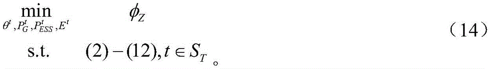
所建立模型的目标函数是在选定的时间区间内,考虑储能电池组出力,使变压器负载率超阈值时间区间数最小;其中阈值受用电情况影响是时变的,用于反映一天中不同时间区间的能源成本差异;目标函数如式(13)所示;The objective function of the established model is to minimize the number of time intervals in which the transformer load rate exceeds the threshold in the selected time interval, considering the output of the energy storage battery pack; the threshold is time-varying due to the influence of power consumption, and is used to reflect the Energy cost difference in different time intervals; the objective function is shown in formula (13);

式中,

建立如下整体多时间区间最优潮流模型:The following overall multi-time interval optimal power flow model is established:
进一步地,整体多时间区间最优潮流模型求解各时间区间储能电池组的功率输出情况,而后基于输出情况给出储能电池组的运行策略;Furthermore, the overall multi-time interval optimal power flow model solves the power output of the energy storage battery group in each time interval, and then gives the operation strategy of the energy storage battery group based on the output situation;
在负荷高峰的时间区间中,接入的储能电池组作为电源放电,为系统输入电能以降低负荷高峰值,在负荷低谷的时间区间中,储能电池则作为负荷的一种,从系统吸收电能从而为后续负荷高峰时间区间的再一次调峰做准备。In the time interval of the peak load, the connected energy storage battery pack is discharged as a power source, and the electric energy is input to the system to reduce the peak load. The electric energy thus prepares for another peak shaving in the subsequent peak load time interval.
进一步地,当有经自回归模型获取的负荷和可再生能源的预测数据时,每个预设的时间间隔求解一次整体多时间区间最优潮流模型,通过增加对储能电池组的调度,实现最佳的调峰效果。Furthermore, when there are load and renewable energy forecast data obtained through the autoregressive model, the overall multi-time interval optimal power flow model is solved once at each preset time interval, and by increasing the scheduling of energy storage battery packs, the realization of The best peaking effect.
进一步地,所述的步骤S3中,构建负荷峰谷差率指标,并以负荷峰谷差率指标对所建立模型的调峰进行负荷波动范围的评估分析;具体如下:Further, in the step S3, the load peak-to-valley difference rate index is constructed, and the load peak-to-valley difference rate index is used to evaluate and analyze the load fluctuation range of the established model; the details are as follows:
负荷峰谷差率:描述一个或多个采样周期内电网负荷的波动范围,其数值越小,表示负荷的波动范围越小;其表达式如下:Load peak-to-valley difference rate: describes the fluctuation range of the grid load within one or more sampling periods, the smaller the value, the smaller the load fluctuation range; its expression is as follows:

式中,β表示负荷峰谷差率;i表示采样周期数;

本发明具有的有益效果如下:The beneficial effects that the present invention has are as follows:
本发明基于储能电池对缓解变压器过载的作用是双重的这一基本思想,构建了基于多时间区间的最优潮流模型,提出了储能电池参与调峰的运行策略,即在负荷高峰期,接入的储能电池作为电源放电为系统输入合适电能,在负荷低谷时储能电池则作为负荷的一种从系统吸收合适电能,实现了对电网的调峰效果,并且缓解了燃煤机组退役时主变压器和线路过载的压力。Based on the basic idea that the energy storage battery plays a dual role in alleviating the overload of the transformer, the present invention constructs an optimal power flow model based on multiple time intervals, and proposes an operation strategy for the energy storage battery to participate in peak regulation, that is, during the peak load period, The connected energy storage battery is discharged as a power supply to input suitable electric energy for the system, and when the load is low, the energy storage battery is used as a load to absorb appropriate electric energy from the system, realizing the peak-shaving effect on the power grid, and alleviating the decommissioning of coal-fired units When the main transformer and line overload pressure.
附图说明Description of drawings
图1是本发明所面向的一个场景图;Fig. 1 is a scene graph that the present invention faces;
图2是本发明提出的基于多时段最优潮流的储能参与调峰运行策略的流程图;Fig. 2 is a flow chart of the energy storage participating in the peak-shaving operation strategy based on the multi-period optimal power flow proposed by the present invention;
图3是本发明应用例中采用所提储能参与调峰的运行策略前后主变压器功率和储能电池功率及荷电状态的结果图。Fig. 3 is a result diagram of main transformer power, energy storage battery power and state of charge before and after adopting the proposed operation strategy of energy storage participating in peak regulation in the application example of the present invention.
具体实施方式Detailed ways
下面结合附图和具体实施方式对本发明做进一步阐述和说明。The present invention will be further elaborated and illustrated below in conjunction with the accompanying drawings and specific embodiments.
在下面的描述中阐述了很多具体细节以便于充分理解本发明,但是本发明还可以采用其他不同于在此描述的其它方式来实施,本领域技术人员可以在不违背本发明内涵的情况下做类似推广,因此本发明不受下面公开的具体实施例的限制。In the following description, a lot of specific details are set forth in order to fully understand the present invention, but the present invention can also be implemented in other ways different from those described here, and those skilled in the art can do it without departing from the meaning of the present invention. By analogy, the present invention is therefore not limited to the specific examples disclosed below.
在本发明的一个较佳实施例中,根据浙江电网实际典型变电站结构,把附图1所示情况作为测试所提运行策略的场景。根据图1所示的场景:500kV骨干网简称为电源G1,通过连接B1和B2的变压器向220kV网络供电。网状的220kV网络被简称为一个有B3—B4三个总线的环,其中一个燃煤发电机G4将被退役。由潮流图可以看出,发电机能够为局部负载提供电源,从而降低变压器T1的负载状况。然而,当它退役后,220kV电网的所有负载都必须由变压器T1提供,导致B1到B2的潮流明显增加,同时导致T1过载,负荷峰值下T1和线路的压力都将增加。In a preferred embodiment of the present invention, according to the actual typical substation structure of Zhejiang Power Grid, the situation shown in Figure 1 is used as a scenario for testing the proposed operation strategy. According to the scenario shown in Figure 1: the 500kV backbone network is referred to as power supply G1 for short, and supplies power to the 220kV network through the transformer connecting B1 and B2. The meshed 220kV network is simply referred to as a ring with three buses B3-B4, and one of the coal-fired generators, G4, will be decommissioned. It can be seen from the power flow diagram that the generator can provide power for partial loads, thereby reducing the load condition of the transformer T1. However, when it is decommissioned, all the loads of the 220kV grid must be provided by transformer T1, resulting in a significant increase in the power flow from B1 to B2, while causing T1 to be overloaded, and the stress on T1 and the line will increase under load peaks.
为了缓解这种变压器和线路过载情况,分布式发电和需求响应是有效的备选方案。然而,由于这些方案的分布式性质或隐私问题,系统操作员可能无法直接访问这些方案。因此,储能调峰被认为是解决这一问题的理想技术。为了验证使用本发明所提储能电池调峰运行策略能有效缓解已识别的变压器过载,根据实际,即将退役的发电机容量为200MW的燃煤火力发电机,假设在退役发电机原址安装了一个100MW/100MWh的储能电站,这在实践中安装更为便捷,因为设施建设和服务线路可以直接重用。To alleviate this transformer and line overload situation, distributed generation and demand response are effective alternatives. However, system operators may not have direct access to these schemes due to their distributed nature or privacy concerns. Therefore, energy storage peak shaving is considered to be an ideal technology to solve this problem. In order to verify that the peak-shaving operation strategy of the energy storage battery proposed in the present invention can effectively alleviate the identified transformer overload, according to the actual situation, a coal-fired thermal power generator with a generator capacity of 200MW to be decommissioned is assumed to be installed at the original site of the decommissioned generator. 100MW/100MWh energy storage power station, which is more convenient to install in practice, because the facility construction and service lines can be directly reused.
本发明提供了一种基于多时间区间最优潮流和储能电池的电网调峰方法,如图2所示,该方法包括如下步骤:首先需收集一定数量的历史数据,根据线性约束和误差最小目标用来得到自回归模型的p个自回归系数;而后根据自回归模型得到所选时间的预测数据;接着根据多时间区段最优潮流模型迭代计算得到储能电池在各时间区段的具体出力情况,迭代过程中通过比较前后两次结果的负荷峰谷差指标优劣来判断是否迭代结束,最终得到合适的储能电池运行策略。具体步骤如下:The present invention provides a power grid peak regulation method based on multi-time interval optimal power flow and energy storage batteries. As shown in Figure 2, the method includes the following steps: first, a certain amount of historical data needs to be collected, and according to the linear constraints and the minimum error The objective is to obtain the p autoregressive coefficients of the autoregressive model; then obtain the forecast data at the selected time according to the autoregressive model; In terms of output, during the iteration process, it is judged whether the iteration is over by comparing the load peak-valley difference indicators of the two results before and after, and finally an appropriate energy storage battery operation strategy is obtained. Specific steps are as follows:
S1:采用时间序列分析法的自回归模型预测负荷和风力/太阳能的数据。具体为:S1: Load and wind/solar data forecasted by autoregressive models using time series analysis. Specifically:
采用时间序列分析法的自回归模型对区域负荷和风力/太阳能数据进行预测,可用自变量数列来进行预测,其预测原理是用现时的干扰和有限项过去的观测值来预测模型的现时值,将预测值用于建立前瞻性优化形式,自回归模型的数学表示方法为:The autoregressive model of the time series analysis method is used to predict the regional load and wind/solar energy data, and the independent variable series can be used for prediction. The prediction principle is to use the current disturbance and the past observation value of the limited items to predict the current value of the model. Using the predicted values to establish a forward-looking optimization form, the mathematical representation of the autoregressive model is:

式中,


......

以
根据式(1),将一定历史负荷或风力/太阳能数据作为历史数据样本


式中,X表示负荷或风力/太阳能。where X represents load or wind/solar power.
S2:考虑一组前瞻时间区间,基于自回归模型的预测数据,每个时间区间可以建立一个直流潮流,以变压器负载率超阈值数最小为目标函数,建立整体多时间区间最优潮流模型。具体为:考虑一组前瞻时间区间ST={p+1,p+2,…,t,…,T0},每个时间区间t可以建立一个直流潮流,如式(3)所示。S2: Considering a set of forward-looking time intervals, based on the forecast data of the autoregressive model, a DC power flow can be established for each time interval, and the objective function is to establish the overall multi-time interval optimal power flow model with the minimum number of transformer load rates exceeding the threshold. Specifically: consider a set of forward-looking time intervals S T ={p+1,p+2,...,t,...,T 0 }, each time interval t can establish a DC power flow, as shown in formula (3).

式中,AG和AESS分别表示发电机和储能电池组的连接矩阵;

首先,利用一组变量Et对储能电池组的荷电状态(SOC)进行跟踪。它与储能电池充放电功率的联系如式(4)所示。First, a set of variables E t is used to track the state of charge (SOC) of the energy storage battery pack. The relationship between it and the charging and discharging power of the energy storage battery is shown in formula (4).

式中,
对于所选系统,功率平衡约束是最重要的约束之一,如式(5)所示。For the selected system, the power balance constraint is one of the most important constraints, as shown in Equation (5).

式中,Ng表示燃煤机组的数量;


发电机的机组出力约束如下:The unit output constraints of the generator are as follows:

式中,
此外,对发电机考虑了爬坡约束,如式(7)所示。但对储能电池组则不考虑,因为储能电池组在以分钟为单位的运行时间间隔下,具有充分的充放电调整率。In addition, the ramp constraint is considered for the generator, as shown in Equation (7). However, it is not considered for the energy storage battery pack, because the energy storage battery pack has a sufficient charge and discharge adjustment rate under the operating time interval in minutes.

式中,RG和
电池储能运行约束:Battery energy storage operating constraints:


式中,


此外,储能电池的能量状态约束如下:In addition, the energy state constraints of the energy storage battery are as follows:


式中,

式(11)表示在所选时间周期内的任一时段储能电池的能量状态不得为负,也不得超过其能量容量限制;式(12)表示经过一个时间周期,储能电池的能量状态应保持平衡,即在一个时间周期内储能电池的充电总量与放电总量应相等。Equation (11) indicates that the energy state of the energy storage battery must not be negative at any time within the selected time period, nor exceed its energy capacity limit; Equation (12) indicates that after a time period, the energy state of the energy storage battery should be Maintain balance, that is, the total charge and discharge of the energy storage battery should be equal within a period of time.
传输线和变压器容量约束情况与功率从一个节点流向另一个节点的形式一致,如式(13)所示。The transmission line and transformer capacity constraints are consistent with the form of power flow from one node to another, as shown in Equation (13).

式中,Tt表示线路导纳矩阵,
式(3)-式(13)中的t都表示第t个时间区间。The t in formula (3) - formula (13) all represent the tth time interval.
所建立模型的目标函数是在选定的时间区间内,考虑储能电池的出力情况,使变压器负载率超阈值数最小化。其中阈值受用电情况影响是时变的,可反映一天中不同时间区间的能源成本差异。目标函数如式(14)所示。The objective function of the established model is to minimize the number of transformer load rates exceeding the threshold within the selected time interval, considering the output of the energy storage battery. The threshold value is time-varying due to the influence of power consumption, which can reflect the energy cost difference in different time intervals of the day. The objective function is shown in formula (14).

式中,

综上,可以建立如下整体多时间区间最优潮流模型:In summary, the following overall multi-time interval optimal power flow model can be established:

当有经自回归模型获取的负荷和可再生能源的预测数据时,每隔一个时间间隔即15分钟求解一次所建立的模型(15)。因此,通过增加对储能电池组的调度,可实现最佳的调峰效果,同时满足各种约束条件,包括缓解变压器的过载压力。When there are load and renewable energy forecast data obtained through the autoregressive model, the established model (15) is solved every 15 minutes. Therefore, by increasing the scheduling of energy storage battery packs, the best peak shaving effect can be achieved while satisfying various constraints, including alleviating the overload pressure of the transformer.
S3:求解所建立的整体多时间区间最优潮流模型,提出储能电池参与调峰的运行策略,并以负荷峰谷差率为指标对该模型的调峰效果进行评估分析。S3: Solve the established overall multi-time interval optimal power flow model, propose an operation strategy for energy storage batteries to participate in peak regulation, and evaluate and analyze the peak regulation effect of the model with the load peak-to-valley difference rate index.
在根据上述所提整体多时间区间最优潮流模型求解得到各时段储能电池组的功率输出情况后,可基于此提出负荷高峰期的储能电池运行策略,即在负荷高峰的时间区间中,接入的储能电池作为电源放电为系统输入合适电能以降低负荷高峰值,在负荷低谷的时间区间中,储能电池则作为负荷的一种从系统吸收合适电能从而为后续负荷高峰时间区间的再一次调峰做准备。After obtaining the power output of the energy storage battery pack at each time period based on the above-mentioned overall multi-time interval optimal power flow model, the operation strategy of the energy storage battery during the peak load period can be proposed based on this, that is, in the time interval of the peak load, The connected energy storage battery is used as a power supply to discharge the appropriate electric energy for the system to reduce the peak load. In the time interval of the low load, the energy storage battery is used as a load to absorb the appropriate electric energy from the system to provide for the subsequent load peak time interval. Prepare for peak shaving again.
为评估分析所提模型的调峰效果,构建负荷峰谷差率指标。具体如下:In order to evaluate and analyze the peak-shaving effect of the proposed model, a load peak-to-valley difference rate index is constructed. details as follows:
负荷峰谷差率:描述一个或多个采样周期内电网负荷的波动范围,其数值越小,表示负荷的波动范围越小。其表达式如下:Load peak-to-valley difference rate: describes the fluctuation range of the grid load within one or more sampling periods, the smaller the value, the smaller the load fluctuation range. Its expression is as follows:

式中,β表示负荷峰谷差率;i表示采样周期数;

附图3为典型夏季高峰日的变压器加载情况及储能充放电运行情况,时间间隔为15分钟。可以观察到储能电池能够通过在非负荷高峰时充电,并在负荷高峰释放能量来缓解变压器的过载,成功实现调峰目的。迭代过程中通过负荷峰谷差指标的比较,可保证所提策略的调峰效果。同时,从中可发现,本策略对于储能电站的容量要求较为灵活。当储能电站容量较小时,可选择负荷非峰值对储能电站适当充电,而后在适当的时间放电即可起到缓解变压器过载和调峰的目的;当储能电站容量较大时,在非负荷高峰期可充入更多的能量,进而通过本策略可实现更好的调峰目的。Attached Figure 3 shows the transformer loading and energy storage charging and discharging operation on a typical summer peak day, with a time interval of 15 minutes. It can be observed that the energy storage battery can relieve the overload of the transformer by charging at non-load peak hours and releasing energy at load peak hours, and successfully achieve the purpose of peak regulation. In the iterative process, the peak-shaving effect of the proposed strategy can be guaranteed by comparing the load peak-to-valley difference index. At the same time, it can be found that this strategy has more flexible requirements for the capacity of energy storage power stations. When the capacity of the energy storage power station is small, you can choose the off-peak load to properly charge the energy storage power station, and then discharge it at an appropriate time to alleviate the transformer overload and peak regulation; when the capacity of the energy storage power station is large, in non-peak More energy can be charged during the peak load period, and better peak shaving can be achieved through this strategy.
以上所述仅为本说明书一个或多个实施例的较佳实施例而已,并不用以限制本说明书一个或多个实施例,凡在本说明书一个或多个实施例的精神和原则之内,所做的任何修改、等同替换、改进等,均应包含在本说明书一个或多个实施例保护的范围之内。The above descriptions are only preferred embodiments of one or more embodiments of this specification, and are not intended to limit one or more embodiments of this specification. Within the spirit and principles of one or more embodiments of this specification, Any modification, equivalent replacement, improvement, etc. should be included in the scope of protection of one or more embodiments of this specification.
Claims (6)


Priority Applications (1)
| Application Number | Priority Date | Filing Date | Title |
|---|---|---|---|
| CN202211600444.XA CN115833203A (en) | 2022-12-13 | 2022-12-13 | A grid peak regulation method based on multi-time interval optimal power flow and energy storage battery |
Applications Claiming Priority (1)
| Application Number | Priority Date | Filing Date | Title |
|---|---|---|---|
| CN202211600444.XA CN115833203A (en) | 2022-12-13 | 2022-12-13 | A grid peak regulation method based on multi-time interval optimal power flow and energy storage battery |
Publications (1)
| Publication Number | Publication Date |
|---|---|
| CN115833203A true CN115833203A (en) | 2023-03-21 |
Family
ID=85547039
Family Applications (1)
| Application Number | Title | Priority Date | Filing Date |
|---|---|---|---|
| CN202211600444.XA Pending CN115833203A (en) | 2022-12-13 | 2022-12-13 | A grid peak regulation method based on multi-time interval optimal power flow and energy storage battery |
Country Status (1)
| Country | Link |
|---|---|
| CN (1) | CN115833203A (en) |
Cited By (3)
| Publication number | Priority date | Publication date | Assignee | Title |
|---|---|---|---|---|
| CN117175666A (en) * | 2023-11-03 | 2023-12-05 | 深圳航天科创泛在电气有限公司 | A load adjustment method and adjustment device for a distributed energy storage power supply system |
| CN118889497A (en) * | 2024-07-15 | 2024-11-01 | 上海勘测设计研究院有限公司 | A method and device for controlling an energy storage system applied to a substation |
| CN119313109A (en) * | 2024-12-16 | 2025-01-14 | 国网江西省电力有限公司经济技术研究院 | A multi-time scale energy storage configuration method and system for eliminating peak loads |
Citations (5)
| Publication number | Priority date | Publication date | Assignee | Title |
|---|---|---|---|---|
| CN106712075A (en) * | 2016-04-26 | 2017-05-24 | 武汉大学 | Peaking strategy optimization method considering safety constraints of wind power integration system |
| CN109742796A (en) * | 2019-01-10 | 2019-05-10 | 华北电力大学 | A kind of Multiple Time Scales coordinated scheduling method of scene extreme misery storage association system |
| CN110601179A (en) * | 2019-08-16 | 2019-12-20 | 南京理工大学 | Receiving-end power grid consumption optimization method for wind power participating in frequency modulation |
| CN111244993A (en) * | 2020-01-21 | 2020-06-05 | 国网湖南省电力有限公司 | A capacity optimization configuration method for energy storage to participate in grid peak regulation application |
| WO2021143075A1 (en) * | 2020-01-17 | 2021-07-22 | 南京东博智慧能源研究院有限公司 | Demand response method taking space-time distribution of electric vehicle charging loads into consideration |
-
2022
- 2022-12-13 CN CN202211600444.XA patent/CN115833203A/en active Pending
Patent Citations (5)
| Publication number | Priority date | Publication date | Assignee | Title |
|---|---|---|---|---|
| CN106712075A (en) * | 2016-04-26 | 2017-05-24 | 武汉大学 | Peaking strategy optimization method considering safety constraints of wind power integration system |
| CN109742796A (en) * | 2019-01-10 | 2019-05-10 | 华北电力大学 | A kind of Multiple Time Scales coordinated scheduling method of scene extreme misery storage association system |
| CN110601179A (en) * | 2019-08-16 | 2019-12-20 | 南京理工大学 | Receiving-end power grid consumption optimization method for wind power participating in frequency modulation |
| WO2021143075A1 (en) * | 2020-01-17 | 2021-07-22 | 南京东博智慧能源研究院有限公司 | Demand response method taking space-time distribution of electric vehicle charging loads into consideration |
| CN111244993A (en) * | 2020-01-21 | 2020-06-05 | 国网湖南省电力有限公司 | A capacity optimization configuration method for energy storage to participate in grid peak regulation application |
Cited By (6)
| Publication number | Priority date | Publication date | Assignee | Title |
|---|---|---|---|---|
| CN117175666A (en) * | 2023-11-03 | 2023-12-05 | 深圳航天科创泛在电气有限公司 | A load adjustment method and adjustment device for a distributed energy storage power supply system |
| CN117175666B (en) * | 2023-11-03 | 2024-01-26 | 深圳航天科创泛在电气有限公司 | A load adjustment method and adjustment device for a distributed energy storage power supply system |
| CN118889497A (en) * | 2024-07-15 | 2024-11-01 | 上海勘测设计研究院有限公司 | A method and device for controlling an energy storage system applied to a substation |
| CN118889497B (en) * | 2024-07-15 | 2025-02-14 | 上海勘测设计研究院有限公司 | Energy storage system control method and device applied to transformer area |
| CN119313109A (en) * | 2024-12-16 | 2025-01-14 | 国网江西省电力有限公司经济技术研究院 | A multi-time scale energy storage configuration method and system for eliminating peak loads |
| CN119313109B (en) * | 2024-12-16 | 2025-06-13 | 国网江西省电力有限公司经济技术研究院 | A multi-time scale energy storage configuration method and system for eliminating peak loads |
Similar Documents
| Publication | Publication Date | Title |
|---|---|---|
| Yan et al. | A cost accounting method of the Li-ion battery energy storage system for frequency regulation considering the effect of life degradation | |
| Pourmousavi et al. | Real-time energy management of a stand-alone hybrid wind-microturbine energy system using particle swarm optimization | |
| CN105207259B (en) | Micro-grid system dispatching method under based on energy management and net state | |
| CN110690702B (en) | An optimal scheduling and operation method of active distribution network considering comprehensive carrying capacity | |
| CN115833203A (en) | A grid peak regulation method based on multi-time interval optimal power flow and energy storage battery | |
| CN105139147A (en) | Economic scheduling method for micro-grid system | |
| CN116565908A (en) | A flexible traction substation energy management method connected to photovoltaic and energy storage systems | |
| Wang et al. | Optimal control of a grid-connected hybrid electrical energy storage system for homes | |
| CN114123280B (en) | Battery energy storage power station energy management method considering system efficiency | |
| CN110034611A (en) | A kind of peak load shifting mixed energy storage system | |
| CN118074225A (en) | A method and system for optimizing the coordinated dispatching of power system sources, grids, loads and storage | |
| CN117856315B (en) | Scheduling method and scheduling device of energy storage system | |
| CN110350589A (en) | A kind of renewable energy and energy storage scheduling model and dispatching method | |
| Wang et al. | A hierarchical control algorithm for managing electrical energy storage systems in homes equipped with PV power generation | |
| CN110276487B (en) | Reactive auxiliary service transaction mechanism in virtual power plant environment | |
| CN114243675B (en) | Active distribution network optimization method and system considering energy storage system and reactive power compensation | |
| CN116706969A (en) | Interactive control method for flexible power distribution system with multiple microgrids based on intelligent soft switch | |
| CN121124129A (en) | Methods, systems, equipment and media for assessing the carrying capacity of distributed photovoltaic power generation in distribution networks | |
| CN105405072A (en) | Island heuristic load reduction model construction method for active power distribution network | |
| CN112039057B (en) | A low-voltage governance method based on two-stage scheduling | |
| CN119813374A (en) | A method and system for optimizing energy dispatching of a flexible power grid | |
| CN110224397A (en) | It is a kind of scene access background under user side battery energy storage cost effectiveness analysis method | |
| Delavaripour et al. | Optimum battery size selection in standalone renewable energy systems | |
| CN113555929B (en) | Retired battery energy storage system considering risks and optimal scheduling method thereof | |
| Wang et al. | Optimal Configuration of Energy Storage in Distribution Networks Based on Full Life Levelized Cost of Electricity |
Legal Events
| Date | Code | Title | Description |
|---|---|---|---|
| PB01 | Publication | ||
| PB01 | Publication | ||
| SE01 | Entry into force of request for substantive examination | ||
| SE01 | Entry into force of request for substantive examination |