CN115828339A - Industrial CT image-based three-dimensional CAD solid model reconstruction method for workpiece with internal defects - Google Patents
Industrial CT image-based three-dimensional CAD solid model reconstruction method for workpiece with internal defects Download PDFInfo
- Publication number
- CN115828339A CN115828339A CN202211123445.XA CN202211123445A CN115828339A CN 115828339 A CN115828339 A CN 115828339A CN 202211123445 A CN202211123445 A CN 202211123445A CN 115828339 A CN115828339 A CN 115828339A
- Authority
- CN
- China
- Prior art keywords
- workpiece
- model
- point cloud
- point
- stl
- Prior art date
- Legal status (The legal status is an assumption and is not a legal conclusion. Google has not performed a legal analysis and makes no representation as to the accuracy of the status listed.)
- Pending
Links
Images


Landscapes
- Analysing Materials By The Use Of Radiation (AREA)
Abstract
本发明公开一种基于工业CT图像的带内部缺陷工件三维CAD实体模型重构方法,步骤包括:1)获取带缺陷工件CT序列图像;2)对带缺陷工件CT序列图像进行处理,得到工件表面STL模型和内部缺陷STL模型;3)对工件原始CAD实体模型和工件STL模型进行配准,对工件STL模型进行空间变换,从而得到空间变换后的工件STL模型;4)根据步骤3)的工件STL模型,生成带内部缺陷工件CAD实体模型。本发明能够实现带内部缺陷工件的CAD实体模型重构,进一步定性和定量分析缺陷对工件整体使用性能的影响。

The invention discloses a method for reconstructing a three-dimensional CAD solid model of a workpiece with internal defects based on industrial CT images. The steps include: 1) acquiring a CT sequence image of the workpiece with defects; 2) processing the CT sequence images of the workpiece with defects to obtain the surface of the workpiece STL model and internal defect STL model; 3) the original CAD entity model of the workpiece and the workpiece STL model are registered, and the workpiece STL model is carried out space transformation, thereby obtaining the workpiece STL model after the space transformation; 4) according to the workpiece of step 3) STL model, generate CAD solid model of the workpiece with internal defects. The invention can realize the reconstruction of the CAD entity model of the workpiece with internal defects, and further qualitatively and quantitatively analyze the influence of defects on the overall performance of the workpiece.
Description
技术领域technical field
本发明涉及机械技术领域,具体是一种基于工业CT图像的带内部缺陷工件三维CAD实体模型重构方法。The invention relates to the field of mechanical technology, in particular to a method for reconstructing a three-dimensional CAD solid model of a workpiece with internal defects based on industrial CT images.
背景技术Background technique
部分工件在制造和使用过程中不可避免地产生各种各样的内部缺陷,为评估内部缺陷对工件使用性能的影响,可建立带内部缺陷工件的三维CAD实体模型,然后通过数字化模拟仿真的方法对缺陷工件进行定量分析。要重构带内部缺陷工件的三维CAD实体模型,首先要对工件内部缺陷进行检测。工业计算机断层成像(ComputedTomography,CT)技术能够在无损条件下,通过重建被检测物体的二维断层图像或三维模型,清晰、准确、直观地展示物体内部的结构、组成、材质及缺陷情况。Some workpieces inevitably produce various internal defects in the process of manufacturing and use. In order to evaluate the impact of internal defects on the performance of the workpiece, a three-dimensional CAD solid model of the workpiece with internal defects can be established, and then digitally simulated Quantitative analysis of defective workpieces. To reconstruct the 3D CAD solid model of the workpiece with internal defects, the internal defects of the workpiece must be detected first. Industrial computed tomography (Computed Tomography, CT) technology can clearly, accurately and intuitively display the internal structure, composition, material and defects of the object by reconstructing the two-dimensional tomographic image or three-dimensional model of the detected object under non-destructive conditions.
目前,利用工业CT技术对带内部缺陷工件的研究主要集中在缺陷三维可视化、缺陷测量和统计以及缺陷演化分析。At present, the research on workpieces with internal defects using industrial CT technology mainly focuses on three-dimensional defect visualization, defect measurement and statistics, and defect evolution analysis.
有的学者通过高分辨CT扫描碳纤维增强复合材料在局部冲击下产生的裂纹,通过分析破坏机制、缺陷的分布,以定量的方式识别工件潜在的损伤和失效机制。Some scholars use high-resolution CT to scan the cracks generated by carbon fiber reinforced composite materials under local impact, and analyze the damage mechanism and defect distribution to quantitatively identify the potential damage and failure mechanism of the workpiece.
有的学者利用工业CT技术对经过低周疲劳实验的2A12铝合金圆柱形试件进行扫描重建,采用三维体绘制对其进行重建,获得与实际裂纹情况吻合良好的三维可视化图像及其尺寸信息。该重建方法效率低,并且在重建过程中易丢失工件的细小内部缺陷。Some scholars use industrial CT technology to scan and reconstruct 2A12 aluminum alloy cylindrical specimens that have undergone low-cycle fatigue experiments, and use 3D volume rendering to reconstruct them, and obtain 3D visualization images and their size information that are in good agreement with the actual crack situation. This reconstruction method is inefficient, and the small internal defects of the workpiece are easily lost during the reconstruction process.
有的学者采用微焦点CT对裂纹进行了三维表面重建和三维可视化,研究了2A50锻铝缺口试样的裂纹前沿扩展增量三维分布,但这种方法仅限于对内部缺陷进行可视化,无法进行定量分析。上述研究,仅是对工件的内部缺陷进行三维表面重建,然后对缺陷的空间位置和尺寸进行观察和测量,但这些研究由于无法获取带内部缺陷工件的三维CAD实体模型,因此不能通过数字化模拟仿真的方式评估内部缺陷对工件整体使用性能的影响。Some scholars have used micro-focus CT to perform three-dimensional surface reconstruction and three-dimensional visualization of cracks, and studied the three-dimensional distribution of crack front growth increments in 2A50 wrought aluminum notched samples, but this method is limited to visualization of internal defects and cannot be quantified analyze. The above-mentioned studies are only to reconstruct the three-dimensional surface of the internal defects of the workpiece, and then observe and measure the spatial position and size of the defects. However, these studies cannot be simulated through digital simulation because the three-dimensional CAD solid model of the workpiece with internal defects cannot be obtained. Evaluate the impact of internal defects on the overall performance of the workpiece.
对带缺陷工件CAD实体模型的重构,目前也进行了部分研究,有的学者为了提高磨损零件的修复效率和可靠性,提出了一种基于逆向工程重建磨损工件CAD实体模型的方法,实现对工件表面磨损缺陷的获取和重构,该方法仅用于带表面缺陷工件的三维CAD实体模型重构,对带内部缺陷工件的重构仍未有较好方法。有的学者提出一种新型的CAD实体模型重建方法,将包含重建对象的参数描述(CAD模板)拟合到网格数据中,生成精度更高的CAD实体模型,此方法依赖于CAD模板,且不适用于对带缺陷工件的CAD实体模型进行重构。Some studies have been carried out on the reconstruction of the CAD entity model of the workpiece with defects. In order to improve the repair efficiency and reliability of the worn parts, some scholars proposed a method based on reverse engineering to reconstruct the CAD entity model of the worn workpiece. Acquisition and reconstruction of workpiece surface wear defects, this method is only used for reconstruction of 3D CAD solid model of workpieces with surface defects, and there is still no better method for reconstruction of workpieces with internal defects. Some scholars have proposed a new CAD solid model reconstruction method, which fits the parameter description (CAD template) containing the reconstructed object to the grid data to generate a CAD solid model with higher accuracy. This method relies on the CAD template, and Not suitable for reconstruction of CAD solid models with defective workpieces.
可见,当前直接重构带内部缺陷工件的三维CAD实体模型存在以下问题:It can be seen that the current direct reconstruction of the 3D CAD solid model of the workpiece with internal defects has the following problems:
(1)在CAD实体模型重构环节中存在大量手工操作,过程复杂繁琐、效率低下;(1) There are a lot of manual operations in the CAD entity model reconstruction process, the process is complicated and cumbersome, and the efficiency is low;
(2)重建结果与个人专业能力紧密相关,结构越复杂的工件重建效率与精度越不能得到保证;(2) The reconstruction results are closely related to personal professional ability, and the reconstruction efficiency and accuracy of workpieces with more complex structures cannot be guaranteed;
(3)缺陷体积占比低,并且没有明显的几何特征,重建过程中细小特征难以保留,模型保真性降低。(3) The proportion of defect volume is low, and there are no obvious geometric features. It is difficult to retain small features in the reconstruction process, and the fidelity of the model is reduced.
发明内容Contents of the invention
本发明的目的是提供一种基于工业CT图像的带内部缺陷工件三维CAD实体模型重构方法,包括以下步骤:The object of the present invention is to provide a kind of reconstruction method of three-dimensional CAD solid model of the band internal defect workpiece based on industrial CT image, comprising the following steps:
1)获取带缺陷工件CT序列图像;1) Obtain CT sequence images of workpieces with defects;
2)对带缺陷工件CT序列图像进行处理,得到工件STL模型;2) Process the CT sequence images of the workpiece with defects to obtain the STL model of the workpiece;
对带缺陷工件CT序列图像进行处理的步骤包括:The steps of processing the CT sequence images of workpieces with defects include:
利用三维CV模型和MC算法对带缺陷工件CT序列图像进行体数据处理和STL模型重建,得到带缺陷工件的STL模型;Using the three-dimensional CV model and MC algorithm to process the volume data and reconstruct the STL model of the CT sequence images of the workpiece with defects, the STL model of the workpiece with defects is obtained;
利用三维CV模型和MC算法对带缺陷工件CT序列图像进行体数据处理和STL模型重建的步骤包括:The steps of volume data processing and STL model reconstruction of CT sequence images of workpieces with defects using 3D CV model and MC algorithm include:
2.1)依次读取工件CT序列图像,得到待处理三维体数据;2.1) sequentially read the CT sequence images of the workpiece to obtain the three-dimensional volume data to be processed;
2.2)利用三维CV模型迭代计算能量函数,使能量函数达到最小;2.2) Utilize the three-dimensional CV model to iteratively calculate the energy function to minimize the energy function;
所述三维CV模型的能量函数F(C,c1,c2)如下所示:The energy function F(C,c 1 ,c 2 ) of the three-dimensional CV model is as follows:
F(C,c1,c2)=μArea(C)+νVolume(C)+λ1∫in(c)|u0(x,y,z)-c1|2dxdydz (1)F(C,c 1 ,c 2 )=μArea(C)+νVolume(C)+λ 1 ∫ in(c) |u 0 (x,y,z)-c 1 | 2 dxdydz (1)
+λ2∫out(C)|u0(x,y,z)-c2|2dxdydz+λ 2 ∫ out(C) |u 0 (x,y,z)-c 2 | 2 dxdydz
其中,Area(C)表示演化曲面的表面积,Volume(C)表示演化曲面包围的体积;c1,c2分别表示演化曲面C内部和外部的像素灰度平均值;常数μ,ν≥0,常数λ1,λ2>0;u0(x,y,z)为组成空间区域上的任一点的灰度值。Among them, Area (C) represents the surface area of the evolution surface, Volume (C) represents the volume surrounded by the evolution surface; c 1 , c 2 represent the average gray value of pixels inside and outside the evolution surface C respectively; the constant μ, ν≥0, Constant λ 1 , λ 2 >0; u 0 (x, y, z) is the gray value of any point on the constituent space area.
利用三维CV模型迭代计算能量函数的步骤包括:The steps of iteratively calculating the energy function using the three-dimensional CV model include:
2.2.1)设置参数μ、参数ν、参数λ1、参数λ2、参数Δt,初始化水平集函数φ0(x,y,z);2.2.1) Set parameter μ, parameter ν, parameter λ 1 , parameter λ 2 , parameter Δt, and initialize the level set function φ 0 (x,y,z);
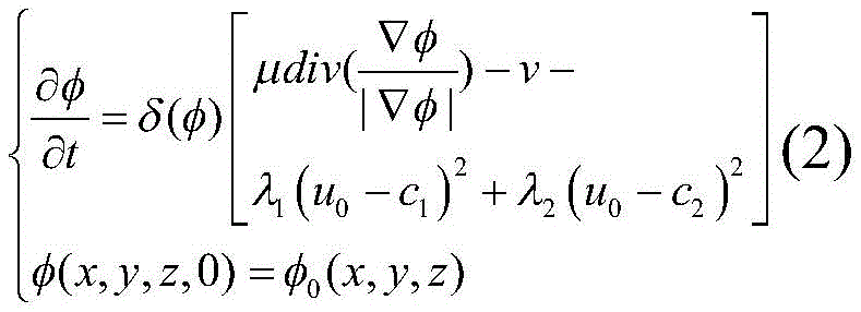
2.2.2)建立能量函数的水平集迭代表达式,即:2.2.2) Establish the level set iteration expression of the energy function, namely:

式中,φ为符号距离函数;H为Heaviside函数;δ为Dirac函数;
2.2.3)利用有限差分方法得到水平集迭代表达式(2)的离散迭代表达式,并利用离散迭代表达式反演曲线C,从而对能量函数进行迭代计算。2.2.3) Obtain the discrete iterative expression of the level set iterative expression (2) by using the finite difference method, and use the discrete iterative expression to invert the curve C, so as to iteratively calculate the energy function.
2.3)每迭代T周期,提取三维CV模型的零水平集,利用MC算法对零水平集进行等值面重建;2.3) Every iteration T period, extract the zero level set of the three-dimensional CV model, and use the MC algorithm to reconstruct the isosurface of the zero level set;
2.4)判断迭代次数是否达到终止迭代次数,若是,则输出由MC算法重建得到的带缺陷工件的STL模型,否则,返回步骤3);2.4) judge whether the number of iterations reaches the number of termination iterations, if so, output the STL model with the defective workpiece reconstructed by the MC algorithm, otherwise, return to step 3);
对带缺陷工件的STL模型进行提取的步骤包括:The steps of extracting the STL model of the workpiece with defects include:
2.2.1)根据带缺陷工件的STL模型各面片的顶点坐标建立边信息表;2.2.1) Establish an edge information table according to the vertex coordinates of each surface of the STL model of the workpiece with defects;
2.2.2)选取一个未标记三角面片作为种子,并进行标记;将标记后的三角面片添加到面片队列中;2.2.2) Select an unmarked triangular patch as a seed and mark it; add the marked triangular patch to the patch queue;
2.2.3)从队列中取出标记三角面片,以所述标记三角面片的三条边作为起点,查找包含标记三角面片任意边的其它未标记面片,并将这些面片打上与标记三角面片相同的标记;2.2.3) Take out the marked triangles from the queue, use the three sides of the marked triangles as the starting point, search for other unmarked faces that contain any side of the marked triangles, and mark these faces with the marked triangles. the same mark for the patch;
2.2.4)重复步骤2.2.3),直至不存在包含标记三角面片任意边的未标记面片;2.2.4) Repeat step 2.2.3) until there is no unmarked facet containing any edge of the marked triangular facet;
2.2.5)判断队列是否为空,若是,则进入步骤2.2.6),否则返回步骤2.2.2);2.2.5) judge whether the queue is empty, if so, then enter step 2.2.6), otherwise return to step 2.2.2);
2.2.6)提取指定区域,将标记相同的面片输出为新的STL模型。提取指定区域,将标记相同的面片输出为新的STL模型;所述指定区域为标记相同的面片组成的一个连通区域,包括工件表面区域和若干内部缺陷区域。2.2.6) Extract the specified area, and output the patches with the same mark as a new STL model. Extract the specified area, and output the same-labeled patches as a new STL model; the specified area is a connected area composed of the same-labeled patches, including the surface area of the workpiece and several internal defect areas.
3)对工件原始CAD实体模型和工件STL模型进行配准,对工件STL模型进行空间变换,从而得到空间变换后的工件STL模型;3) Register the original CAD entity model of the workpiece and the STL model of the workpiece, and perform spatial transformation on the STL model of the workpiece, so as to obtain the STL model of the workpiece after the spatial transformation;
对工件原始CAD实体模型和工件STL模型进行配准的步骤包括:The steps of registering the original CAD solid model of the workpiece and the STL model of the workpiece include:
3.1)利用Delaunay三角剖分法进行工件原始CAD实体模型点云化,得到工件原始点云模型;3.1) Use the Delaunay triangulation method to convert the original CAD entity model of the workpiece into a point cloud to obtain the original point cloud model of the workpiece;
3.2)利用快速点特征直方图算法对工件原始CAD实体模型和工件STL模型进行点云粗配准的步骤包括:3.2) The steps of performing rough point cloud registration on the original CAD entity model of the workpiece and the STL model of the workpiece using the fast point feature histogram algorithm include:
3.2.1)对于目标点云Q和源点云P,利用公式(3),分别计算点云集的FPFH,即:3.2.1) For the target point cloud Q and the source point cloud P, use the formula (3) to calculate the FPFH of the point cloud set, namely:

式中,ωi是查询点pq与紧邻点pi之间距离的度量,k是每个点邻域内的点平均数量,SPFH(pi)和SPFH(pq)分别是以pi和pq为查询点的简化特征直方图对应的值;In the formula, ω i is the measure of the distance between the query point p q and the adjacent point p i , k is the average number of points in the neighborhood of each point, SPFH(p i ) and SPFH(p q ) are based on p i and p q is the value corresponding to the simplified feature histogram of the query point;
3.2.2)获取采样点:对源点云P进行采样获取m个点,为了使得采样点空间尽可能大的覆盖点云集,限制采样点间的距离最小值;3.2.2) Obtain sampling points: Sampling the source point cloud P to obtain m points, in order to make the sampling point space as large as possible to cover point clouds, limit the minimum distance between sampling points;
3.2.3)寻找点对:根据源点云中的采样点在目标点云中查找FPFH相近的一个或多个对应点,随机选取一个作为空间变换点对;3.2.3) Find point pairs: search for one or more corresponding points in the target point cloud with similar FPFH according to the sampling points in the source point cloud, and randomly select one as a space transformation point pair;
3.2.4)空间变换:根据选择的点对进行刚体变换矩阵计算,并对源点云进行空间变换,完成工件原始点云模型和工件STL模型的点云粗配准。3.2.4) Space transformation: Calculate the rigid body transformation matrix according to the selected point pairs, and perform space transformation on the source point cloud, and complete the point cloud rough registration of the original point cloud model of the workpiece and the STL model of the workpiece.
3.3)利用迭代最近点算法对工件原始点云模型和第一次刚体变换后的工件STL模型进行点云精配准,得到刚体变换矩阵;3.3) Use the iterative closest point algorithm to perform point cloud fine registration on the original point cloud model of the workpiece and the STL model of the workpiece after the first rigid body transformation, and obtain the rigid body transformation matrix;
利用迭代最近点算法对工件原始点云模型和第一次刚体变换后的工件STL模型进行点云精配准的步骤包括:The steps of performing point cloud fine registration on the original point cloud model of the workpiece and the STL model of the workpiece after the first rigid body transformation by using the iterative closest point algorithm include:
3.3.1)记第一次刚体变换后的工件STL模型的点云集合为

3.3.2)对于点Pi,在点云集合X搜索最近点作为对应点,并写入对应点集
3.3.3)根据对应点集Q计算精配准的旋转变换矩阵R和平移变换矩阵T;3.3.3) Calculate the rotation transformation matrix R and the translation transformation matrix T of fine registration according to the corresponding point set Q;
3.3.4)根据精配准的旋转变换矩阵R和平移变换矩阵T对第一次刚体变换后的内部缺陷STL模型进行刚体变换;3.3.4) Perform rigid body transformation on the internal defect STL model after the first rigid body transformation according to the precisely registered rotation transformation matrix R and translation transformation matrix T;
3.3.5)计算相邻两次变换的误差改变量Ek,若误差改变量Ek小于给定的阈值τ,则结束配准过程,否则判断迭代次数k是否达到最大迭代次数,若是,则结束配准过程,否则,令迭代次数k=k+1,并返回步骤3.3.1);3.3.5) Calculate the error change E k of two adjacent transformations, if the error change E k is less than a given threshold τ, then end the registration process, otherwise judge whether the number of iterations k reaches the maximum number of iterations, if so, then End the registration process, otherwise, set the number of iterations k=k+1, and return to step 3.3.1);
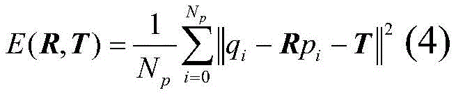
其中,当前刚体变换后误差测度函数E(R,T)如下所示:Among them, the error measurement function E(R,T) after the current rigid body transformation is as follows:

式中,R表示精配准的旋转变换矩阵,T表示平移变换矩阵。In the formula, R represents the rotation transformation matrix of fine registration, and T represents the translation transformation matrix.
3.4)利用刚体变换矩阵对第一次刚体变换后的内部缺陷STL模型进行空间变换,从而得到空间变换后的工件STL模型。3.4) Use the rigid body transformation matrix to perform space transformation on the internal defect STL model after the first rigid body transformation, so as to obtain the workpiece STL model after space transformation.
4)根据步骤3)的工件STL模型,生成带内部缺陷工件CAD实体模型。4) According to the STL model of the workpiece in step 3), a CAD solid model of the workpiece with internal defects is generated.
生成带内部缺陷工件CAD实体模型的步骤包括:The steps for generating a CAD solid model of a workpiece with internal defects include:
4.1)对空间变换后的工件STL模型进行拓扑重构,得到缺陷CAD实体模型,步骤包括:4.1) Carry out topological reconstruction to the workpiece STL model after space transformation, and obtain the defect CAD entity model, the steps include:
4.1.1)采用三轴分块排序算法删除重复顶点,步骤包括:4.1.1) Using the three-axis block sorting algorithm to delete duplicate vertices, the steps include:
4.1.1.1)创建顶点数组X、Y、Z,输入内部缺陷STL模型,每次读取一个顶点的三个坐标值(x,y,z);4.1.1.1) Create vertex arrays X, Y, Z, input the internal defect STL model, and read three coordinate values (x, y, z) of a vertex each time;
4.1.1.2)根据坐标值判断顶点是否已经保存:由坐标x、y、z值依次进行判断,若在对应的顶点数组中不存在其值,则进入步骤4.1.1.3),若坐标x值存在,则转向坐标x指向的Y数组判断坐标y是否存在,否则进入步骤4.1.1.3);4.1.1.2) Determine whether the vertex has been saved according to the coordinate value: judge by the coordinate x, y, z value in turn, if there is no value in the corresponding vertex array, then enter step 4.1.1.3), if the coordinate x value exists , then turn to the Y array pointed to by the coordinate x to judge whether the coordinate y exists, otherwise enter step 4.1.1.3);
若坐标y存在,则转向坐标y指向的Z数组判断坐标z是否存在,否则进入步骤4.1.1.3);If the coordinate y exists, turn to the Z array pointed to by the coordinate y to judge whether the coordinate z exists, otherwise enter step 4.1.1.3);
若坐标z存在,则不保存当前坐标值(x,y,z),并返回4.1.1.1),否则,进入步骤4.1.1.3);If the coordinate z exists, do not save the current coordinate value (x, y, z), and return to 4.1.1.1); otherwise, go to step 4.1.1.3);
4.1.1.3)将坐标值(x,y,z)保存到对应的X,Y,Z数组中,并进行排序;4.1.1.3) Save the coordinate values (x, y, z) into the corresponding X, Y, Z arrays, and sort them;
排序规则为:保存坐标x后,排序X数组,并相应变换坐标x指向的Y、Z数组;保存坐标y后,则排序Y数组,并相应变换坐标xy指向的Z数组;保存坐标z后,,对Z数组进行排序。The sorting rules are: after saving the coordinate x, sort the X array, and correspondingly transform the Y and Z arrays pointed to by the coordinate x; after saving the coordinate y, sort the Y array, and correspondingly transform the Z array pointed to by the coordinate xy; after saving the coordinate z, , to sort the Z array.
4.1.2)建立顶点、边、面数据表;4.1.2) Establish vertex, edge and surface data tables;
其中,创建顶点数据表的步骤包括:根据从X数组出发,确定每个坐标x对应的坐标y和坐标z,并作为新顶点坐标(x,y,z)加入到顶点表中;Wherein, the step of creating the vertex data table includes: starting from the X array, determining the coordinate y and the coordinate z corresponding to each coordinate x, and adding them to the vertex table as new vertex coordinates (x, y, z);
创建边数据表的步骤包括:根据每个网格的三个顶点坐标两两创建边,判断创建的边是否在边数据表中,若不在,则建立此边与顶点表中对应顶点的索引,创建边信息,并将创建的边加入到边数据表中;The steps of creating an edge data table include: creating edges in pairs according to the coordinates of the three vertices of each grid, judging whether the created edge is in the edge data table, if not, establishing the index of the edge and the corresponding vertex in the vertex table, Create side information and add the created side to the side data table;
创建面数据表的步骤包括:将面的编号及其对应法矢量、组成面的三个顶点和三条边的的索引共同作为面信息加入到面数据表中;The step of creating the surface data table includes: adding the number of the surface and its corresponding normal vector, the indexes of the three vertices and the three edges forming the surface together as surface information to the surface data table;
4.1.3)利用重建后的三角面片间拓扑关系,以边为核心,对所有的三角顶点进行实体重构,由点及边,生成三角面,将所有的三角面合并为一个整体,得到封闭的空间边界,根据封闭的边界面生成缺陷CAD实体模型;4.1.3) Using the reconstructed topological relationship between the triangles, take the edge as the core, reconstruct all the triangle vertices, generate triangles from the points and edges, merge all the triangles into a whole, and get Closed space boundary, generate defect CAD solid model according to the closed boundary surface;
4.2)对内部缺陷CAD实体模型与工件原始CAD实体模型进行布尔运算,生成带缺陷工件的CAD实体模型。4.2) Carry out Boolean operations on the CAD entity model of internal defects and the original CAD entity model of the workpiece to generate a CAD entity model of the workpiece with defects.
值得说明的是,本专利针对带内部缺陷工件的三维CAD实体模型难以获取的问题,在工业CT技术的基础上,提出了一种基于工业CT图像重构带内部缺陷工件的三维CAD实体模型方法,该方法主要分为三步:(1)内部缺陷三维分割和提取。(2)工件CAD实体模型与重建模型配准。(3)带内部缺陷工件CAD实体模型生成。It is worth noting that this patent aims at the problem that it is difficult to obtain a 3D CAD solid model of a workpiece with internal defects. On the basis of industrial CT technology, a method for reconstructing a 3D CAD solid model of a workpiece with internal defects based on industrial CT images is proposed. , the method is mainly divided into three steps: (1) 3D segmentation and extraction of internal defects. (2) The CAD entity model of the workpiece is registered with the reconstructed model. (3) The CAD solid model of the workpiece with internal defects is generated.
本发明的技术效果是毋庸置疑的,本发明的有益效果如下:Technical effect of the present invention is beyond doubt, and beneficial effect of the present invention is as follows:
针对带内部缺陷工件的三维CAD实体模型难以获取的问题,本发明结合工业CT技术,充分利用工件设计阶段存在的原始CAD实体模型,将工业CT图像中提取出的内部缺陷信息直接在工件原始CAD实体模型中重构出来。Aiming at the problem that it is difficult to obtain the three-dimensional CAD solid model of the workpiece with internal defects, the present invention combines industrial CT technology, fully utilizes the original CAD solid model existing in the workpiece design stage, and directly stores the internal defect information extracted from the industrial CT image in the original CAD of the workpiece Refactored out of the solid model.
本发明首先从带内部缺陷工件的工业CT序列图像中重建得到工件的STL模型和缺陷的STL模型;然后为了获取内部缺陷在工件原始CAD实体模型中的正确位置,对工件的STL模型与原始CAD实体模型进行配准;最后将内部缺陷STL模型实体化,与工件原始CAD实体模型进行布尔运算后生成带内部缺陷工件的三维CAD实体模型。通过对实际燃烧室镶块的三维CAD实体模型重构,验证了本发明的实际有效性。The present invention first reconstructs the STL model of the workpiece and the STL model of the defect from the industrial CT sequence image of the workpiece with internal defects; The solid model is registered; finally, the internal defect STL model is solidified, and the original CAD solid model of the workpiece is performed with Boolean operations to generate a 3D CAD solid model of the workpiece with internal defects. The actual effectiveness of the invention is verified by reconstructing the three-dimensional CAD solid model of the actual combustion chamber insert.
本发明主要针对带内部缺陷工件数字化分析中CAD实体模型难以获取的问题,发明了一种基于工业CT图像重构带缺陷工件三维CAD实体模型的方法,为带内部缺陷工件的数字化模型仿真提供了直接准确的模型基础,进而能够更加精确地评估工件的使用性能和使用寿命。The present invention mainly aims at the problem that it is difficult to obtain the CAD entity model in the digital analysis of workpieces with internal defects, and invents a method for reconstructing the three-dimensional CAD entity model of workpieces with defects based on industrial CT images, which provides a digital model simulation for workpieces with internal defects The direct and accurate model basis enables more accurate evaluation of the service performance and service life of the workpiece.
本发明通过内部缺陷工件的工业CT序列图像获取缺陷信息,充分利用设计阶段存在的三维CAD实体模型,经过缺陷分割及提取、模型配准和三维CAD实体模型重构,解决了带内部缺陷工件的三维CAD实体模型难以获取的问题。通过燃烧室镶块的三维CAD实体模型重构并且进行有限元仿真验证了本发明的有效性,该发明同样适用于含小体积或多目标内部缺陷的工件实体模型重构。该发明能为后续针对特定带缺陷工件的数字化模拟仿真提供直接准确的模型支撑,在综合考虑方法实用性、适应性和优化方便的基础上设计技术路线。The present invention obtains defect information through industrial CT sequence images of internal defect workpieces, fully utilizes the 3D CAD entity model existing in the design stage, and solves the problem of internal defect workpieces through defect segmentation and extraction, model registration, and 3D CAD entity model reconstruction. The problem that the 3D CAD solid model is difficult to obtain. The effectiveness of the invention is verified by reconstructing the three-dimensional CAD solid model of the combustion chamber insert and performing finite element simulation, and the invention is also applicable to the reconstruction of the solid model of the workpiece containing small volume or multi-target internal defects. The invention can provide direct and accurate model support for subsequent digital simulation of specific workpieces with defects, and design a technical route based on comprehensive consideration of the method's practicability, adaptability and optimization convenience.
本发明能够实现带内部缺陷工件的CAD实体模型重构,可以进一步定性和定量分析缺陷对工件整体使用性能的影响;本发明能够有效控制重构时间,避免人为通过逆向工程方法带来的耗时、工件细小特征消失等问题。The invention can realize the reconstruction of the CAD entity model of workpieces with internal defects, and can further qualitatively and quantitatively analyze the influence of defects on the overall performance of the workpiece; the invention can effectively control the reconstruction time and avoid the time-consuming artificial reverse engineering method , The small features of the workpiece disappear and other problems.
附图说明Description of drawings
图1为方法实现的流程图;Fig. 1 is the flowchart that method realizes;
图2为燃烧室镶块工业CT序列图像;Figure 2 is the industrial CT sequence image of the combustion chamber insert;
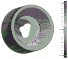
图3为带气孔的燃烧室镶块STL模型;Fig. 3 is the STL model of the combustion chamber insert with air holes;
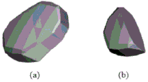
图4(a)为燃烧室镶块STL模型,(b)为气孔STL模型(放大约9倍);Figure 4(a) is the STL model of the combustion chamber insert, and (b) is the STL model of the air hole (enlarged about 9 times);
图5为燃烧室镶块CAD实体模型点云化,图5(a)为CAD实体模型,图5(b)为点云模型(面片显示),图5(c)为点云模型(网格显示);Fig. 5 is the point cloud of the CAD solid model of the combustion chamber insert, Fig. 5(a) is the CAD solid model, Fig. 5(b) is the point cloud model (surface display), and Fig. 5(c) is the point cloud model (network grid display);
图6为燃烧室镶块CAD实体模型与重建模型的配准,图6(a)为初始位置,图6(b)为粗配准结果,图6(c)为精配准结果;Figure 6 shows the registration of the combustion chamber insert CAD solid model and the reconstructed model, Figure 6(a) is the initial position, Figure 6(b) is the rough registration result, and Figure 6(c) is the fine registration result;
图7为燃烧室镶块CAD实体模型与重建模型的配准检测效果;Figure 7 shows the registration detection effect of the combustion chamber insert CAD solid model and the reconstructed model;
图8为气孔与燃烧室镶块位置变化(箭头所指为气孔),图8(a)为初始位置,图8(b)为空间变换后位置;Figure 8 shows the position change of the air hole and the combustion chamber insert (the arrow points to the air hole), Figure 8(a) is the initial position, and Figure 8(b) is the position after space transformation;
图9为气孔CAD实体模型,图9为(a)外观图,图9(b)为截面图;Fig. 9 is a pore CAD entity model, Fig. 9 is (a) an appearance view, and Fig. 9(b) is a cross-sectional view;
图10为带气孔的燃烧室镶块CAD实体模型,图10(a)为外观图(箭头所指为气孔),图10(b)为纵向截面图,图10(c)为局部图;Figure 10 is a CAD solid model of a combustion chamber insert with air holes, Figure 10(a) is an appearance view (the arrow points to air holes), Figure 10(b) is a longitudinal section view, and Figure 10(c) is a partial view;
图11为燃烧室镶块热力学仿真压力云图。Fig. 11 is the pressure cloud diagram of the thermodynamic simulation of the combustion chamber insert.
具体实施方式Detailed ways
下面结合实施例对本发明作进一步说明,但不应该理解为本发明上述主题范围仅限于下述实施例。在不脱离本发明上述技术思想的情况下,根据本领域普通技术知识和惯用手段,做出各种替换和变更,均应包括在本发明的保护范围内。The present invention will be further described below in conjunction with the examples, but it should not be understood that the scope of the subject of the present invention is limited to the following examples. Without departing from the above-mentioned technical ideas of the present invention, various replacements and changes made according to common technical knowledge and conventional means in this field shall be included in the protection scope of the present invention.
实施例1:Example 1:
参见图1至图11,一种基于工业CT图像的带内部缺陷工件三维CAD实体模型重构方法,包括以下步骤:Referring to Figures 1 to 11, a method for reconstructing a three-dimensional CAD solid model of a workpiece with internal defects based on industrial CT images includes the following steps:
1)获取带缺陷工件CT序列图像;1) Obtain CT sequence images of workpieces with defects;
2)对带缺陷工件CT序列图像进行处理,得到工件表面STL模型和内部缺陷STL模型;2) Process the CT sequence images of the workpiece with defects to obtain the STL model of the surface of the workpiece and the STL model of internal defects;
对带缺陷工件CT序列图像进行处理的步骤包括:The steps of processing the CT sequence images of workpieces with defects include:
2.1)利用三维CV模型(Chan-Vese模型,水平集模型)和MC算法(移动立方体算法,marchingcube算法)对带缺陷工件CT序列图像进行体数据处理和STL模型重建,得到带缺陷工件的STL模型;2.1) Use the 3D CV model (Chan-Vese model, level set model) and MC algorithm (moving cube algorithm, marchingcube algorithm) to process the volume data and reconstruct the STL model of the CT sequence images of the workpiece with defects, and obtain the STL model of the workpiece with defects ;
利用三维CV模型和MC算法对带缺陷工件CT序列图像进行体数据处理和STL模型重建的步骤包括:The steps of volume data processing and STL model reconstruction of CT sequence images of workpieces with defects using 3D CV model and MC algorithm include:
2.1.1)依次读取工件CT序列图像,得到待处理三维体数据;2.1.1) sequentially read the CT sequence images of the workpiece to obtain the three-dimensional volume data to be processed;
2.1.2)利用三维CV模型迭代计算能量函数,使能量函数达到最小;2.1.2) Use the three-dimensional CV model to iteratively calculate the energy function to minimize the energy function;
所述三维CV模型的能量函数F(C,c1,c2)如下所示:The energy function F(C,c 1 ,c 2 ) of the three-dimensional CV model is as follows:
F(C,c1,c2)=μArea(C)+νVolume(C)+λ1∫in(c)|u0(x,y,z)-c1|2dxdydz (1)F(C,c 1 ,c 2 )=μArea(C)+νVolume(C)+λ 1 ∫ in(c) |u 0 (x,y,z)-c 1 | 2 dxdydz (1)
+λ2∫out(C)|u0(x,y,z)-c2|2dxdydz+λ 2 ∫ out(C) |u 0 (x,y,z)-c 2 | 2 dxdydz
其中,Area(C)表示演化曲面的表面积,Volume(C)表示演化曲面包围的体积;c1,c2分别表示演化曲面C内部和外部的像素灰度平均值;常数μ,ν≥0,常数λ1,λ2>0;u0(x,y,z)为组成空间区域上的任一点的灰度值。Among them, Area (C) represents the surface area of the evolution surface, Volume (C) represents the volume surrounded by the evolution surface; c 1 , c 2 represent the average gray value of pixels inside and outside the evolution surface C respectively; the constant μ, ν≥0, Constant λ 1 , λ 2 >0; u 0 (x, y, z) is the gray value of any point on the constituent space area.
利用三维CV模型迭代计算能量函数的步骤包括:The steps of iteratively calculating the energy function using the three-dimensional CV model include:
2.1.2.1)设置参数μ、参数ν、参数λ1、参数λ2、参数Δt,初始化水平集函数φ0(x,y,z);2.1.2.1) Set parameter μ, parameter ν, parameter λ 1 , parameter λ 2 , parameter Δt, and initialize level set function φ 0 (x,y,z);
2.1.2.2)建立能量函数的水平集迭代表达式,即:2.1.2.2) Establish the level set iterative expression of the energy function, namely:

式中,φ为符号距离函数;H为Heaviside函数;δ为Dirac函数;▽为梯度算子;u0指代u0(x,y,z);In the formula, φ is the signed distance function; H is the Heaviside function; δ is the Dirac function; ▽ is the gradient operator; u 0 refers to u 0 (x, y, z);
2.1.2.3)利用有限差分方法得到水平集迭代表达式(2)的离散迭代表达式,并利用离散迭代表达式反演曲线C,从而对能量函数进行迭代计算。2.1.2.3) Obtain the discrete iterative expression of the level set iterative expression (2) by using the finite difference method, and use the discrete iterative expression to invert the curve C, so as to iteratively calculate the energy function.
2.1.3)每迭代T周期,提取三维CV模型的零水平集,利用MC算法对零水平集进行等值面重建;2.1.3) Every iteration T period, extract the zero level set of the three-dimensional CV model, and use the MC algorithm to reconstruct the isosurface of the zero level set;
2.1.4)判断迭代次数是否达到终止迭代次数,若是,则输出由MC算法重建得到的带缺陷工件的STL模型,否则,返回步骤3);2.1.4) Judging whether the number of iterations reaches the number of termination iterations, if so, output the STL model of the workpiece with defects reconstructed by the MC algorithm, otherwise, return to step 3);
2.2)对带缺陷工件的STL模型进行提取,得到工件STL模型和内部缺陷STL模型。2.2) Extract the STL model of the workpiece with defects to obtain the workpiece STL model and internal defect STL model.
对带缺陷工件的STL模型进行提取的步骤包括:The steps of extracting the STL model of the workpiece with defects include:
2.2.1)根据带缺陷工件的STL模型各面片的顶点坐标建立边信息表;2.2.1) Establish an edge information table according to the vertex coordinates of each surface of the STL model of the workpiece with defects;
2.2.2)选取一个未标记三角面片作为种子,并进行标记;将标记后的三角面片添加到面片队列中;2.2.2) Select an unmarked triangular patch as a seed and mark it; add the marked triangular patch to the patch queue;
2.2.3)从队列中取出标记三角面片,以所述标记三角面片的三条边作为起点,查找包含标记三角面片任意边的其它未标记面片,并将这些面片打上与标记三角面片相同的标记;2.2.3) Take out the marked triangles from the queue, use the three sides of the marked triangles as the starting point, search for other unmarked faces that contain any side of the marked triangles, and mark these faces with the marked triangles. the same mark for the patch;
2.2.4)重复步骤2.2.3),直至不存在包含标记三角面片任意边的未标记面片;2.2.4) Repeat step 2.2.3) until there is no unmarked facet containing any edge of the marked triangular facet;
2.2.5)判断队列是否为空,若是,则进入步骤2.2.6),否则返回步骤2.2.2);2.2.5) judge whether the queue is empty, if so, then enter step 2.2.6), otherwise return to step 2.2.2);
2.2.6)提取指定区域,将标记相同的面片输出为新的STL模型;所述指定区域为标记相同的面片组成的一个连通区域,包括工件表面区域和若干内部缺陷区域。面片标记包括两种,其中一种标记对应工件STL模型,另一种对应内部缺陷STL模型。2.2.6) Extract the specified area, and output the same-labeled patches as a new STL model; the specified area is a connected area composed of the same-labeled patches, including the surface area of the workpiece and several internal defect areas. There are two kinds of patch marks, one of which corresponds to the workpiece STL model, and the other corresponds to the internal defect STL model.
3)对工件原始CAD实体模型和工件完整的STL模型进行配准,对工件STL模型进行空间变换,从而得到空间变换后的内部缺陷STL模型;3) Register the original CAD entity model of the workpiece and the complete STL model of the workpiece, and perform space transformation on the STL model of the workpiece, so as to obtain the internal defect STL model after space transformation;
对工件原始CAD实体模型和工件STL模型进行配准的步骤包括:The steps of registering the original CAD solid model of the workpiece and the STL model of the workpiece include:
3.1)利用Delaunay三角剖分法进行工件原始CAD实体模型(例如燃烧室镶块CAD实体模型)点云化,得到工件原始点云模型;3.1) Use the Delaunay triangulation method to convert the point cloud of the original CAD solid model of the workpiece (such as the CAD solid model of the combustion chamber insert) to obtain the original point cloud model of the workpiece;
3.2)利用快速点特征直方图算法对工件原始CAD实体模型和工件STL模型进行点云粗配准的步骤包括:3.2) The steps of performing rough point cloud registration on the original CAD entity model of the workpiece and the STL model of the workpiece using the fast point feature histogram algorithm include:
3.2.1)对于目标点云Q和源点云P,利用公式(3),分别计算点云集的FPFH,即:3.2.1) For the target point cloud Q and the source point cloud P, use the formula (3) to calculate the FPFH of the point cloud set, namely:

式中,ωi是查询点pq与紧邻点pi之间距离的度量,k是每个点邻域内的点平均数量,SPFH(pi)和SPFH(pq)分别是以pi和pq为查询点的简化特征直方图对应的值;In the formula, ω i is the measure of the distance between the query point p q and the adjacent point p i , k is the average number of points in the neighborhood of each point, SPFH(p i ) and SPFH(p q ) are based on p i and p q is the value corresponding to the simplified feature histogram of the query point;
3.2.2)获取采样点:对源点云P进行采样获取m个点,为了使得采样点空间尽可能大的覆盖点云集,限制采样点间的距离最小值;3.2.2) Obtain sampling points: Sampling the source point cloud P to obtain m points, in order to make the sampling point space as large as possible to cover point clouds, limit the minimum distance between sampling points;
3.2.3)寻找点对:根据源点云中的采样点在目标点云中查找FPFH相近的一个或多个对应点,随机选取一个作为空间变换点对;3.2.3) Find point pairs: search for one or more corresponding points in the target point cloud with similar FPFH according to the sampling points in the source point cloud, and randomly select one as a space transformation point pair;
3.2.4)空间变换:根据选择的点对进行刚体变换矩阵计算,并对源点云进行空间变换,完成工件原始点云模型和工件STL模型的点云粗配准。3.2.4) Space transformation: Calculate the rigid body transformation matrix according to the selected point pairs, and perform space transformation on the source point cloud, and complete the point cloud rough registration of the original point cloud model of the workpiece and the STL model of the workpiece.
3.3)利用迭代最近点算法对工件原始点云模型和第一次刚体变换后的工件STL模型进行点云精配准,得到刚体变换矩阵;3.3) Use the iterative closest point algorithm to perform point cloud fine registration on the original point cloud model of the workpiece and the STL model of the workpiece after the first rigid body transformation, and obtain the rigid body transformation matrix;
利用迭代最近点算法对工件原始点云模型和第一次刚体变换后的工件STL模型进行点云精配准的步骤包括:The steps of performing point cloud fine registration on the original point cloud model of the workpiece and the STL model of the workpiece after the first rigid body transformation by using the iterative closest point algorithm include:
3.3.1)记第一次刚体变换后的工件STL模型的点云集合为

3.3.2)对于点Pi,在点云集合X搜索最近点作为对应点,并写入对应点集
3.3.3)根据对应点集Q计算精配准的旋转变换矩阵R和平移变换矩阵T;3.3.3) Calculate the rotation transformation matrix R and the translation transformation matrix T of fine registration according to the corresponding point set Q;
3.3.4)根据精配准的旋转变换矩阵R和平移变换矩阵T对第一次刚体变换后的工件STL模型进行刚体变换;3.3.4) Perform rigid body transformation on the workpiece STL model after the first rigid body transformation according to the precisely registered rotation transformation matrix R and translation transformation matrix T;
3.3.5)计算相邻两次变换的误差改变量Ek,若误差改变量Ek小于给定的阈值τ,则结束配准过程,否则判断迭代次数k是否达到最大迭代次数,若是,则结束配准过程,否则,令迭代次数k=k+1,并返回步骤3.3.1);3.3.5) Calculate the error change E k of two adjacent transformations, if the error change E k is less than a given threshold τ, then end the registration process, otherwise judge whether the number of iterations k reaches the maximum number of iterations, if so, then End the registration process, otherwise, set the number of iterations k=k+1, and return to step 3.3.1);
其中,当前刚体变换后误差测度函数E(R,T)如下所示:Among them, the error measurement function E(R,T) after the current rigid body transformation is as follows:

式中,R表示精配准的旋转变换矩阵,T表示平移变换矩阵。qi、pi采用坐标形式表征。In the formula, R represents the rotation transformation matrix of fine registration, and T represents the translation transformation matrix. qi and pi are represented in the form of coordinates.
3.4)利用刚体变换矩阵对第一次刚体变换后的工件STL模型进行空间变换,从而得到空间变换后的工件STL模型。3.4) Use the rigid body transformation matrix to perform space transformation on the workpiece STL model after the first rigid body transformation, so as to obtain the space transformed workpiece STL model.
4)根据步骤3)的工件STL模型,生成带内部缺陷工件CAD实体模型。4) According to the STL model of the workpiece in step 3), a CAD solid model of the workpiece with internal defects is generated.
生成带内部缺陷工件CAD实体模型的步骤包括:The steps for generating a CAD solid model of a workpiece with internal defects include:
4.1)对空间变换后的工件STL模型进行拓扑重构,得到缺陷CAD实体模型,步骤包括:4.1) Carry out topological reconstruction to the workpiece STL model after space transformation, and obtain the defect CAD entity model, the steps include:
4.1.1)采用三轴分块排序算法(参考崔树标,张宜生,梁书云,李德群.STL面片中冗余顶点的快速滤除算法及其应用.中国机械工程,2001(02):173-175+117)删除重复顶点,步骤包括:4.1.1) Using a three-axis block sorting algorithm (refer to Cui Shubiao, Zhang Yisheng, Liang Shuyun, Li Dequn. A fast filtering algorithm for redundant vertices in STL patches and its application. China Mechanical Engineering, 2001(02): 173-175 +117) Delete duplicate vertices, the steps include:
4.1.1.1)创建顶点数组X、Y、Z,输入内部缺陷STL模型,每次读取一个顶点的三个坐标值(x,y,z);4.1.1.1) Create vertex arrays X, Y, Z, input the internal defect STL model, and read three coordinate values (x, y, z) of a vertex each time;
4.1.1.2)根据坐标值判断顶点是否已经保存:由坐标x、y、z值依次进行判断,若在对应的顶点数组中不存在其值,则进入步骤4.1.1.3),若坐标x值存在,则转向坐标x指向的Y数组判断坐标y是否存在,否则进入步骤4.1.1.3);4.1.1.2) Determine whether the vertex has been saved according to the coordinate value: judge by the coordinate x, y, z value in turn, if there is no value in the corresponding vertex array, then enter step 4.1.1.3), if the coordinate x value exists , then turn to the Y array pointed to by the coordinate x to judge whether the coordinate y exists, otherwise enter step 4.1.1.3);
若坐标y存在,则转向坐标y指向的Z数组判断坐标z是否存在,否则进入步骤4.1.1.3);If the coordinate y exists, turn to the Z array pointed to by the coordinate y to judge whether the coordinate z exists, otherwise enter step 4.1.1.3);
若坐标z存在,则不保存当前坐标值(x,y,z),并返回4.1.1.1),否则,进入步骤4.1.1.3);If the coordinate z exists, do not save the current coordinate value (x, y, z), and return to 4.1.1.1); otherwise, go to step 4.1.1.3);
4.1.1.3)将坐标值(x,y,z)保存到对应的X,Y,Z数组中,并进行排序;4.1.1.3) Save the coordinate values (x, y, z) into the corresponding X, Y, Z arrays, and sort them;
排序规则为:保存坐标x后,排序X数组,并相应变换坐标x指向的Y、Z数组;保存坐标y后,则排序Y数组,并相应变换坐标x y指向的Z数组;保存坐标z后,,对Z数组进行排序。The sorting rules are: after saving the coordinate x, sort the X array, and correspondingly transform the Y and Z arrays pointed to by the coordinate x; after saving the coordinate y, sort the Y array, and correspondingly transform the Z array pointed to by the coordinate x y; after saving the coordinate z, , to sort the Z array.
4.1.2)建立顶点、边、面数据表;4.1.2) Establish vertex, edge and surface data tables;
其中,创建顶点数据表的步骤包括:根据从X数组出发,确定每个坐标x对应的坐标y和坐标z,并作为新顶点坐标(x,y,z)加入到顶点表中;Wherein, the step of creating the vertex data table includes: starting from the X array, determining the coordinate y and the coordinate z corresponding to each coordinate x, and adding them to the vertex table as new vertex coordinates (x, y, z);
创建边数据表的步骤包括:根据每个网格的三个顶点坐标两两创建边,判断创建的边是否在边数据表中,若不在,则建立此边与顶点表中对应顶点的索引,创建边信息,并将创建的边加入到边数据表中;The steps of creating an edge data table include: creating edges in pairs according to the coordinates of the three vertices of each grid, judging whether the created edge is in the edge data table, if not, establishing the index of the edge and the corresponding vertex in the vertex table, Create side information and add the created side to the side data table;
创建面数据表的步骤包括:将面的编号及其对应法矢量、组成面的三个顶点和三条边的的索引共同作为面信息加入到面数据表中;The step of creating the surface data table includes: adding the number of the surface and its corresponding normal vector, the indexes of the three vertices and the three edges forming the surface together as surface information to the surface data table;
4.1.3)利用重建后的三角面片间拓扑关系,以边为核心,对所有的三角顶点进行实体重构,由点及边,生成三角面,将所有的三角面合并为一个整体,得到封闭的空间边界,根据封闭的边界面生成缺陷CAD实体模型;4.1.3) Using the reconstructed topological relationship between the triangles, take the edge as the core, reconstruct all the triangle vertices, generate triangles from the points and edges, merge all the triangles into a whole, and get Closed space boundary, generate defect CAD solid model according to the closed boundary surface;
4.2)对内部缺陷CAD实体模型与工件原始CAD实体模型进行布尔运算,生成带缺陷工件的CAD实体模型。4.2) Carry out Boolean operations on the CAD entity model of internal defects and the original CAD entity model of the workpiece to generate a CAD entity model of the workpiece with defects.
实施例2:Example 2:
一种基于工业CT图像的带内部缺陷工件三维CAD实体模型重构方法,包括以下步骤:A method for reconstructing a three-dimensional CAD solid model of a workpiece with internal defects based on industrial CT images, comprising the following steps:
1.内部缺陷三维分割及提取1. Three-dimensional segmentation and extraction of internal defects
(1)输入工业CT扫描的带内部缺陷工件CT序列图像;(1) Input the CT sequence image of the workpiece with internal defects from industrial CT scanning;
(2)利用三维CV模型进行体数据处理和STL模型重建,得到带内部缺陷工件的STL模型,结果如图3;(2) Use the 3D CV model for volume data processing and STL model reconstruction to obtain the STL model of the workpiece with internal defects, as shown in Figure 3;
(3)燃烧室镶块和内部缺陷的STL模型提取,结果如图4。(3) STL model extraction of combustion chamber inserts and internal defects, the results are shown in Figure 4.
2.工件CAD实体模型与重建模型配准2. Registration of workpiece CAD solid model and reconstruction model
(1)使用Delaunay三角剖分进行燃烧室镶块CAD实体模型点云化,如图5;(1) Use Delaunay triangulation to convert the CAD solid model of the combustion chamber into a point cloud, as shown in Figure 5;
(2)利用快速点特征直方图(FastPointFeatureHistogram,FPFH)算法进行点云粗配准;(2) Use the Fast Point Feature Histogram (FPFH) algorithm to perform coarse registration of point clouds;
(3)通过迭代最近点(IterativeClosestPoint,ICP)算法进行点云精配准,结果如图6,对配准精度进行检测和展示,结果如图7。(3) Perform point cloud fine registration through the Iterative Closest Point (ICP) algorithm, the result is shown in Figure 6, and the registration accuracy is detected and displayed, the result is shown in Figure 7.
(4)对内部缺陷进行刚体变换得到,缺陷与工件原始CAD实体模型的位置关系,如图8。(4) Perform rigid body transformation on internal defects to obtain the positional relationship between defects and the original CAD entity model of the workpiece, as shown in Figure 8.
3.带内部缺陷工件CAD实体模型生成3. Generation of CAD solid model of workpiece with internal defects
(1)内部缺陷STL模型拓扑重构,内部缺陷重构后的CAD实体模型如图9所示;(1) The topology reconstruction of the internal defect STL model, the CAD entity model of the internal defect reconstruction is shown in Figure 9;
(2)将内部缺陷CAD实体模型与工件原始CAD实体模型进行布尔运算,生成带缺陷工件的CAD实体模型,如图10;(2) Carry out Boolean operation with the internal defect CAD entity model and the original CAD entity model of the workpiece to generate the CAD entity model of the defective workpiece, as shown in Figure 10;
(3)将重构的带内部缺陷工件的CAD实体模型导入ANSYS有限元仿真软件中,验证重构模型的可用性,结果如图11。(3) Import the reconstructed CAD solid model of the workpiece with internal defects into the ANSYS finite element simulation software to verify the availability of the reconstructed model. The results are shown in Figure 11.
实施例3:Example 3:
一种基于工业CT图像的带内部缺陷工件三维CAD实体模型重构方法,主要步骤见实施例2,其中,内部缺陷三维分割及提取步骤包括:A method for reconstructing a three-dimensional CAD solid model of a workpiece with internal defects based on industrial CT images. The main steps are shown in Embodiment 2, wherein the three-dimensional segmentation and extraction steps of internal defects include:
三维CV模型直接从体数据进行缺陷分割,获取内部封闭的缺陷包围曲面。将工业CT序列图像组成的空间区域看作是由两个灰度值近似为常量的背景和目标组成,其灰度值分别为u0 b和u0 t。此时有一封闭演化曲面C将空间区域分割开来,曲面内外的空间区域分别用in(C)和out(C)表示。设组成空间区域上的任一点的灰度值为u0(x,y,z),则三维CV模型的能量函数为:The 3D CV model performs defect segmentation directly from the volume data, and obtains an internally closed defect-surrounding surface. The spatial region composed of industrial CT sequence images is regarded as composed of background and target whose gray values are approximately constant, and their gray values are u 0 b and u 0 t respectively. At this time, there is a closed evolution surface C to divide the space region, and the space regions inside and outside the surface are denoted by in(C) and out(C) respectively. Assuming that the gray value of any point on the constituent space area is u 0 (x, y, z), the energy function of the three-dimensional CV model is:
F(C,c1,c2)=μArea(C)+νVolume(C)+λ1∫in(c)|u0(x,y,z)-c1|2dxdydz (1)F(C,c 1 ,c 2 )=μArea(C)+νVolume(C)+λ 1 ∫ in(c) |u 0 (x,y,z)-c 1 | 2 dxdydz (1)
+λ2∫out(C)|u0(x,y,z)-c2|2dxdydz+λ 2 ∫ out(C) |u 0 (x,y,z)-c 2 | 2 dxdydz
其中,Area(C)表示演化曲面的表面积,Volume(C)表示演化曲面包围的体积,c1,c2分别表示演化曲面C内部和外部的像素灰度平均值,常数μ,ν≥0,λ1,λ2>0,其中λ1,λ2常取1。Among them, Area (C) represents the surface area of the evolution surface, Volume (C) represents the volume surrounded by the evolution surface, c 1 and c 2 represent the average gray value of the pixels inside and outside the evolution surface C, constant μ, ν≥0, λ 1 , λ 2 >0, where λ 1 , λ 2 always take 1.
三维CV模型曲面演化的过程就是求解式(1)使其取值最小化,通过引入符号距离函数φ、Heaviside函数H、Dirac函数δ,时间变量t得到式(1)的水平集迭代表达式为:The process of surface evolution of the 3D CV model is to solve the formula (1) to minimize its value. By introducing the signed distance function φ, the Heaviside function H, the Dirac function δ, and the time variable t, the level set iteration expression of the formula (1) is obtained as :

通过使用有限差分方法得到式(2)的离散迭代表达式,就可以通过编程来实现对工业CT序列切片组成的三维体数据进行分割。By using the finite difference method to obtain the discrete iterative expression of formula (2), the three-dimensional volume data composed of industrial CT sequence slices can be segmented through programming.
使用三维CV模型和MC算法对样件进行体数据处理和STL模型重建的实验步骤如下:The experimental steps for volume data processing and STL model reconstruction of the sample using the 3D CV model and MC algorithm are as follows:
步骤Ⅰ:依次读取带内部缺陷工件的工业CT序列图像,得到待处理三维体数据;Step Ⅰ: sequentially read the industrial CT sequence images of the workpiece with internal defects to obtain the three-dimensional volume data to be processed;
步骤II:设置参数μ,ν,λ1,λ2,Δt,初始化水平集函数φ0(x,y,z);Step II: Set parameters μ, ν, λ 1 , λ 2 , Δt, and initialize the level set function φ 0 (x, y, z);
步骤Ⅲ:通过离散迭代方式不断迭代水平集函数,直到达到终止条件;Step Ⅲ: Continuously iterate the level set function through discrete iteration until the termination condition is reached;
步骤Ⅳ:每迭代一段时间,使用MC算法对零水平集进行等值面重建用以显示;Step Ⅳ: Use MC algorithm to reconstruct the isosurface of the zero level set for display every time period of iteration;
步骤Ⅴ:迭代终止时,保存由MC算法重建得到的三角网格STL模型,以待下一步分析。Step Ⅴ: When the iteration terminates, save the triangular mesh STL model reconstructed by the MC algorithm for further analysis.
对经过三角网格表面重建得到的带内部缺陷工件STL模型,需要将内部缺陷的STL模型从中提取出来。工件表面和内部缺陷表面分别由不同的三角面片围成封闭曲面,组成不同的连通区域,提取其中的缺陷STL模型可以使用连通区域分析法。在由三角面片组成的STL模型中,任一边必须被两个三角形共享,将含有邻边的等值三角面片连通的区域认为是一个整体,通过迭代归并的方式将整个等值面划分为相互独立的连通区域,通过此方法完成对缺陷区域和工件本身的标定和提取。具体实现步骤如下:For the STL model of the workpiece with internal defects obtained through triangular mesh surface reconstruction, the STL model of internal defects needs to be extracted from it. The surface of the workpiece and the surface of the internal defect are respectively surrounded by different triangular faces to form a closed surface, forming different connected regions, and the connected region analysis method can be used to extract the defect STL model. In the STL model composed of triangular patches, any side must be shared by two triangles, and the area connected by the equivalent triangular patches containing adjacent sides is considered as a whole, and the entire isosurface is divided into Connected areas that are independent of each other, through this method, the calibration and extraction of the defect area and the workpiece itself are completed. The specific implementation steps are as follows:
步骤Ⅰ:输入带缺陷工件的STL模型,根据面片中的顶点坐标建立边信息表;Step Ⅰ: Input the STL model of the workpiece with defects, and establish the edge information table according to the vertex coordinates in the patch;
步骤II:以某个三角面片作为种子,将其标记后加入面片队列;Step II: Use a triangle patch as a seed, mark it and add it to the patch queue;
步骤Ⅲ:从队列中依次取出标记的三角面片,以面片的三条边作为起点,查找包含此边的其它未标记面片视为连通集合,将其标记后加入面片队列;Step Ⅲ: Take out the marked triangular patches from the queue one by one, take the three edges of the patch as the starting point, find other unmarked patches containing this edge as a connected set, mark them and add them to the patch queue;
步骤Ⅳ:当队列为空时,所有已经标记的面片作为一个连通区域;Step Ⅳ: When the queue is empty, all marked patches are regarded as a connected region;
步骤Ⅴ:重复步骤II-Ⅳ,直到所有面片标记完成;Step Ⅴ: Repeat steps II-Ⅳ until all patches are marked;
步骤Ⅵ:提取指定区域,将标记相同的面片输出为新的STL模型。Step Ⅵ: Extract the specified area, and export the patches with the same mark as a new STL model.
对带气孔的燃烧室镶块STL模型进行分析,气孔缺陷面积占比为1.26%,体积占比为0.27%,此实验验证了本发明在对小体积缺陷进行三维分割时的效果较好。Analyzing the STL model of the combustion chamber insert with pores, the proportion of the defect area of the pores is 1.26%, and the proportion of the volume is 0.27%. This experiment verifies that the present invention has a better effect in three-dimensional segmentation of small-volume defects.
实施例4:Example 4:
一种基于工业CT图像的带内部缺陷工件三维CAD实体模型重构方法,主要步骤见实施例2,其中,工件CAD实体模型与重建模型配准的步骤包括:A method for reconstructing a three-dimensional CAD solid model of a workpiece with internal defects based on industrial CT images, the main steps of which are shown in Embodiment 2, wherein the steps of registering the CAD solid model of the workpiece with the reconstructed model include:
(1)粗配准实现(1) Realization of coarse registration
粗配准的目的是通过初始配准将源点云经过刚体变换后,使得源点云与目标点云的位姿尽可能接近,快速点特征直方图(FastPointFeatureHistogram,FPFH)算法具有求解速度快,应用方便的特点,本文采用FPFH算法来进行粗匹配。The purpose of coarse registration is to transform the source point cloud through rigid body transformation through initial registration, so that the pose of the source point cloud and the target point cloud are as close as possible. The fast point feature histogram (FPFH) algorithm has a fast solution speed and is applied For convenience, this paper uses the FPFH algorithm for rough matching.
FPFH是对点特征直方图(PointFeatureHistogram,PFH)的计算复杂度优化而来,PFH是基于某中心点与其邻域之间的关系,通过计算法线之间的作用关系,使用<α,φ,θ,d>四个特征元素值构成一个描述子,其中<α,φ,θ>表示两点间法线的角度偏差,d=||p2-p1||2表示两点间的欧式距离,最终通过计算邻域内所有两点间的描述子形成一个多维直方图去表达模型表面的特征变化情况。FPFH is optimized from the computational complexity of the point feature histogram (PointFeatureHistogram, PFH). PFH is based on the relationship between a central point and its neighbors. By calculating the relationship between normals, use <α, φ, θ, d> four feature element values constitute a descriptor, where <α, φ, θ> represents the angle deviation of the normal between two points, d=||p 2 -p 1 || 2 represents the Euclidean Finally, a multi-dimensional histogram is formed by calculating the descriptors between all two points in the neighborhood to express the feature change of the model surface.
对于具有n个点的点云数据,若每个点邻域内的点数量为k,则PFH的理论计算复杂度为o(nk2),FPFH只计算邻域内中心点与紧邻点之间的特征元素,形成简化点特征直方图(SimplifiedPointFeatureHistogram,SPFH),提高计算速度。计算过程如下:For point cloud data with n points, if the number of points in the neighborhood of each point is k, the theoretical computational complexity of PFH is o(nk 2 ), and FPFH only calculates the features between the center point and the adjacent point in the neighborhood Elements form a simplified point feature histogram (SimplifiedPointFeatureHistogram, SPFH), which improves the calculation speed. The calculation process is as follows:
步骤Ⅰ:只计算查询点Pq邻域内与其紧邻点Pi之间的特征元素,形成SPFH;Step Ⅰ: Only calculate the feature elements between the query point P q neighborhood and its immediate neighbor point P i to form SPFH;
步骤II:对于Pq邻域内的每个紧邻点Pi,确定以Pi为查询点的SPFH;Step II: For each adjacent point P i in the neighborhood of P q , determine the SPFH with P i as the query point;
步骤Ⅲ:使用Pq和所有Pi的SPFH加权计算Pq的FPFH,加权计算公式如下:Step Ⅲ: Calculate the FPFH of P q by weighting the SPFH of P q and all P i . The weighted calculation formula is as follows:

其中,ωi是查询点Pq与紧邻点Pi之间距离的度量,表示点对所占(Pq,Pi)的权重。Among them, ω i is the measure of the distance between the query point P q and the adjacent point P i , and represents the weight of (P q , P i ) occupied by the point pair.
通过FPFH算法快速获得某点云集内一点的FPFH特征,应用于点云配准就是比较两点云中点对的FPFH特征是否接近。粗配准算法过程如下:The FPFH feature of a point in a point cloud is quickly obtained through the FPFH algorithm, and the application to point cloud registration is to compare whether the FPFH features of point pairs in two point clouds are close. The rough registration algorithm process is as follows:
步骤Ⅰ:计算FPFH。对于目标点云Q和源点云P,分别计算点云集的FPFH;Step Ⅰ: Calculate FPFH. For the target point cloud Q and the source point cloud P, calculate the FPFH of the point cloud set respectively;
步骤II:获取采样点。对源点云P进行采样获取m个点,为了使得采样点空间尽可能大的覆盖点云集,限制采样点间的距离最小值;Step II: Obtain sampling points. Sampling the source point cloud P to obtain m points, in order to make the sampling point space as large as possible to cover the point cloud set, limit the minimum distance between sampling points;
步骤Ⅲ:寻找点对。根据源点云中的采样点在目标点云中查找FPFH相近的一个或多个对应点,随机选取一个作为空间变换点对;Step Ⅲ: Find point pairs. According to the sampling points in the source point cloud, one or more corresponding points close to the FPFH are found in the target point cloud, and one is randomly selected as a space transformation point pair;
步骤Ⅳ:空间变换。根据选择的点对进行刚体变换矩阵计算,并对源点云进行空间变换使其接近目标点云。Step Ⅳ: Space transformation. The rigid body transformation matrix is calculated according to the selected point pairs, and the source point cloud is spatially transformed to make it close to the target point cloud.
(2)精配准实现(2) Realization of fine registration
精配准是在粗配准的基础上使得两点云模型的位姿进一步接近,得到最佳的匹配位置。目前使用最广泛的是迭代最近点(IterativeClosestPoint,ICP)算法[22]。该算法的本质是基于最小二乘法的最优匹配,执行从确定对应关系的点集到计算最优刚体变换的迭代过程,直至测量误差满足设定的收敛精度或达到最大的迭代次数,从而结束整个配准过程。Fine registration is based on rough registration to make the poses of the two point cloud models closer to get the best matching position. Currently the most widely used is the Iterative Closest Point (ICP) algorithm [22] . The essence of the algorithm is the optimal matching based on the least squares method, and it executes the iterative process from determining the corresponding point set to calculating the optimal rigid body transformation until the measurement error meets the set convergence accuracy or reaches the maximum number of iterations, thus ending the entire registration process.
假设存在源点云集合


其中,R表示精配准的旋转变换矩阵,T表示平移变换矩阵。Among them, R represents the rotation transformation matrix of fine registration, and T represents the translation transformation matrix.
对于目标点云X和源点云P,ICP算法的配准过程如下:For the target point cloud X and the source point cloud P, the registration process of the ICP algorithm is as follows:
步骤Ⅰ:选择对应关系点集。计算目标点云X中源点云P的最近对应点集Q,使其满足P:Q=C(P,X),C表示寻找最近点Step Ⅰ: Select the corresponding point set. Calculate the closest corresponding point set Q of the source point cloud P in the target point cloud X, so that it satisfies P: Q=C(P,X), and C means looking for the nearest point
步骤II:由对应点集计算刚体变换矩阵R和T。Step II: Calculate the rigid body transformation matrices R and T from the corresponding point set.
步骤Ⅲ:位置信息变换。根据II中矩阵对源点云进行刚体变换到达新位置。Step Ⅲ: Position information conversion. According to the matrix in II, the source point cloud is rigidly transformed to a new position.
步骤Ⅳ:对于相邻的两次变换计算其误差的改变量Ek,若小于给定的阈值τ则达到迭代终止条件,结束配准过程。否则令迭代次数k=k+1,若k未达到最大迭代次数则转向步骤Ⅰ继续迭代Step IV: Calculate the error change E k for two adjacent transformations, if it is less than a given threshold τ, the iteration termination condition is reached, and the registration process ends. Otherwise, let the number of iterations k=k+1, if k does not reach the maximum number of iterations, turn to step I to continue iterating
实施例5:Example 5:
一种基于工业CT图像的带内部缺陷工件三维CAD实体模型重构方法,主要步骤见实施例2,其中,带内部缺陷工件CAD实体模型生成的步骤包括:A method for reconstructing a three-dimensional CAD solid model of a workpiece with internal defects based on industrial CT images. The main steps are shown in Embodiment 2, wherein the steps for generating the CAD solid model of a workpiece with internal defects include:
(1)内部缺陷的STL模型拓扑重构(1) STL model topology reconstruction of internal defects
对于表达三角网格模型的STL文件格式,存储了用于逼近CAD实体模型的所有三角面片信息,包含了构成每个三角面片的三个顶点坐标和所在平面的法矢量信息,构成的空间区域封闭且有界,与边界表示法(Boundary/Representation,B-Rep)表达的CAD实体模型相比,STL模型不具备三角网格间的拓扑关系,如没有边与面的所属关系。因此,从STL模型转化为B-Rep实体模型的关键步骤就是重建三角网格间的拓扑关系。对拓扑关系的重建主要包括删除重复顶点和建立顶点、面、边数据表两步。For the STL file format that expresses the triangular mesh model, it stores all the triangular patch information used to approximate the CAD solid model, including the coordinates of the three vertices that make up each triangular patch and the normal vector information of the plane where it is located. The space formed The area is closed and bounded. Compared with the CAD solid model expressed by the boundary representation (Boundary/Representation, B-Rep), the STL model does not have the topological relationship between the triangular meshes, such as the relationship between edges and faces. Therefore, the key step in transforming from STL model to B-Rep solid model is to reconstruct the topological relationship between triangular meshes. The reconstruction of topological relationship mainly includes two steps: deleting duplicate vertices and establishing data tables of vertices, faces and edges.
步骤Ⅰ:删除重复顶点。STL文件重复存储了相接面的顶点信息,这些重复顶点的信息存储造成STL文件占用内存大,并且降低拓扑关系重建的效率。对重复顶点的删除采用三轴分块排序算法[22]。具体实现过程如下:Step Ⅰ: Delete duplicate vertices. The STL file repeatedly stores the vertex information of the contact surface. The information storage of these repeated vertices causes the STL file to occupy a large memory and reduces the efficiency of topological relationship reconstruction. The three-axis block sorting algorithm [22] is used to delete duplicate vertices. The specific implementation process is as follows:
(a)创建顶点数组X、Y、Z,输入STL文件,每次读取一个顶点的三个坐标值(x,y,z);(a) Create vertex arrays X, Y, Z, input the STL file, and read three coordinate values (x, y, z) of a vertex each time;
(b)根据坐标值判断顶点是否已经保存。由x、y、z值依次进行判断,若在对应的顶点数组中不存在其值则进入(c),如x值存在,则转向x指向的Y数组判断y,若y存在,则转向y指向的Z数组判断z,若z存在,则进入(a);(b) Determine whether the vertex has been saved according to the coordinate value. Judgment is made sequentially by the values of x, y, and z. If the value does not exist in the corresponding vertex array, enter (c). If the value of x exists, turn to the Y array pointed to by x to judge y. If y exists, turn to y The Z array pointed to judges z, if z exists, enter (a);
(c)将转入此项中未保存的x、y、z值保存到对应的X,Y,Z数组中,并进行排序。规则为,若保存x后,排序X数组,并相应变换其指向的Y、Z数组;若保存y后,则排序Y数组,并相应变换其指向的Z数组;若保存z,则对Z数组进行排序。(c) Save the unsaved x, y, and z values transferred into this item to the corresponding X, Y, and Z arrays, and sort them. The rule is, if you save x, sort the X array, and change the Y and Z arrays it points to accordingly; if you save y, sort the Y array, and change the Z array it points to accordingly; if you save z, then change the Z array Sort.
步骤II:建立顶点、边、面数据表Step II: Create vertex, edge, face data tables
(a)创建顶点数据表。根据步骤Ⅰ中得到的三个坐标值数组X、Y、Z,由X数组出发,确定每个x对应的y坐标和z坐标,将其作为一个新顶点坐标(x,y,z)加入到顶点表中;(a) Create a vertex data table. According to the three coordinate value arrays X, Y, Z obtained in step I, starting from the X array, determine the y coordinate and z coordinate corresponding to each x, and add it as a new vertex coordinate (x, y, z) to in the vertex table;
(b)创建边数据表。在(a)去重后的顶点坐标表中,根据每个网格的三个顶点坐标两两创建边,判断是否在边数据表中,若不在,则建立此边与顶点表中对应顶点的索引,创建边信息,加入到边数据表中;(b) Create an edge data table. In (a) the vertex coordinate table after deduplication, create edges in pairs according to the three vertex coordinates of each grid, and judge whether it is in the edge data table, if not, establish the relationship between this edge and the corresponding vertex in the vertex table Index, create side information, and add it to the side data table;
(c)创建面数据表。将面的编号及其对应法矢量,组成面的三个顶点和三条边的的索引共同作为面信息加入到面数据表中。(c) Create a surface data table. The number of the surface and its corresponding normal vector, the indices of the three vertices and the three edges that make up the surface are added to the surface data table as surface information.
完成STL模型拓扑重构后,为了最大可能的保留缺陷空间信息,直接利用重建后的三角面片间拓扑关系,以边为核心,对所有的三角顶点进行实体重构,由点及边,生成三角面,再将所有的三角面合并为一个整体,同STL模型一样组成封闭的空间边界,再从封闭的边界面生成B-Rep实体模型。After completing the topology reconstruction of the STL model, in order to retain the defect space information as much as possible, the topological relationship between the reconstructed triangles is directly used, and the edges are used as the core to reconstruct the entities of all triangle vertices, and the points and edges are generated. Triangular faces, and then merge all the triangular faces into a whole to form a closed space boundary like the STL model, and then generate a B-Rep solid model from the closed boundary surface.
(2)布尔运算(2) Boolean operation
本发明借助OpenCasCade开源库中提供的布尔运算功能完成三维实体间布尔运算,最终重构得到带内部缺陷工件的三维CAD实体模型。The present invention uses the Boolean operation function provided in the OpenCasCade open source library to complete the Boolean operation between three-dimensional entities, and finally reconstructs to obtain the three-dimensional CAD entity model of the workpiece with internal defects.
实施例6:Embodiment 6:
一种基于工业CT图像的带内部缺陷工件三维CAD实体模型重构方法,包括以下步骤:A method for reconstructing a three-dimensional CAD solid model of a workpiece with internal defects based on industrial CT images, comprising the following steps:
1)获取带缺陷工件CT序列图像;1) Obtain CT sequence images of workpieces with defects;
2)对带缺陷工件CT序列图像进行处理,得到工件STL模型;2) Process the CT sequence images of the workpiece with defects to obtain the STL model of the workpiece;
3)对工件原始CAD实体模型和工件STL模型进行配准,并对工件STL模型进行空间变换,从而得到空间变换后的工件STL模型;3) Register the original CAD entity model of the workpiece and the STL model of the workpiece, and perform spatial transformation on the STL model of the workpiece, so as to obtain the STL model of the workpiece after the spatial transformation;
4)根据空间变换后的工件STL模型,生成带内部缺陷工件CAD实体模型。4) According to the STL model of the workpiece after space transformation, a CAD solid model of the workpiece with internal defects is generated.
实施例7:Embodiment 7:
一种基于工业CT图像的带内部缺陷工件三维CAD实体模型重构方法,主要内容见实施例6,其中,对带缺陷工件CT序列图像进行处理的步骤包括:A method for reconstructing a three-dimensional CAD solid model of a workpiece with internal defects based on industrial CT images, the main content of which is shown in Embodiment 6, wherein the steps of processing the CT sequence images of the workpiece with defects include:
利用三维CV模型和MC算法对带缺陷工件CT序列图像进行体数据处理和STL模型重建,得到带缺陷工件的STL模型。Using the 3D CV model and MC algorithm to process the volume data and reconstruct the STL model of the CT sequence images of the workpiece with defects, the STL model of the workpiece with defects is obtained.
实施例8:Embodiment 8:
一种基于工业CT图像的带内部缺陷工件三维CAD实体模型重构方法,主要内容见实施例6,其中,利用三维CV模型和MC算法对带缺陷工件CT序列图像进行体数据处理和STL模型重建的步骤包括:A method for reconstructing a three-dimensional CAD solid model of a workpiece with internal defects based on industrial CT images, the main content of which is shown in Embodiment 6, wherein, the three-dimensional CV model and the MC algorithm are used to perform volume data processing and STL model reconstruction on the CT sequence images of the workpiece with defects The steps include:
1)依次读取工件CT序列图像,得到待处理三维体数据;1) sequentially read the CT sequence images of the workpiece to obtain the three-dimensional volume data to be processed;
2)利用三维CV模型迭代计算能量函数,使能量函数达到最小;2) Using the three-dimensional CV model to iteratively calculate the energy function to minimize the energy function;
3)每迭代T周期,提取三维CV模型的零水平集,利用MC算法对零水平集进行等值面重建;3) Extract the zero-level set of the three-dimensional CV model every iteration T period, and use the MC algorithm to reconstruct the isosurface of the zero-level set;
4)判断迭代次数是否达到终止迭代次数,若是,则输出由MC算法重建得到的带缺陷工件的STL模型,否则,返回步骤3);4) Judging whether the number of iterations reaches the number of termination iterations, if so, output the STL model with the defective workpiece reconstructed by the MC algorithm, otherwise, return to step 3);
实施例9:Embodiment 9:
一种基于工业CT图像的带内部缺陷工件三维CAD实体模型重构方法,主要内容见实施例6,其中,所述三维CV模型的能量函数F(C,c1,c2)如下所示:A method for reconstructing a three-dimensional CAD solid model of a workpiece with internal defects based on industrial CT images, the main content of which is shown in Embodiment 6, wherein the energy function F(C,c 1 ,c 2 ) of the three-dimensional CV model is as follows:
F(C,c1,c2)=μArea(C)+νVolume(C)+λ1∫in(c)|u0(x,y,z)-c1|2dxdydz (1)F(C,c 1 ,c 2 )=μArea(C)+νVolume(C)+λ 1 ∫ in(c) |u 0 (x,y,z)-c 1 | 2 dxdydz (1)
+λ2∫out(C)|u0(x,y,z)-c2|2dxdydz+λ 2 ∫ out(C) |u 0 (x,y,z)-c 2 | 2 dxdydz
其中,Area(C)表示演化曲面的表面积,Volume(C)表示演化曲面包围的体积;c1,c2分别表示演化曲面C内部和外部的像素灰度平均值;常数μ,ν≥0,常数λ1,λ2>0;u0(x,y,z)为组成空间区域上的任一点的灰度值。Among them, Area (C) represents the surface area of the evolution surface, Volume (C) represents the volume surrounded by the evolution surface; c 1 , c 2 represent the average gray value of pixels inside and outside the evolution surface C respectively; the constant μ, ν≥0, Constant λ 1 , λ 2 >0; u 0 (x, y, z) is the gray value of any point on the constituent space area.
实施例10:Example 10:
一种基于工业CT图像的带内部缺陷工件三维CAD实体模型重构方法,主要内容见实施例6,其中,利用三维CV模型迭代计算能量函数的步骤包括:A method for reconstructing a three-dimensional CAD solid model of a workpiece with internal defects based on industrial CT images, the main content of which is shown in Embodiment 6, wherein the step of using the three-dimensional CV model to iteratively calculate the energy function includes:
1)设置参数μ、参数ν、参数λ1、参数λ2、参数Δt,初始化水平集函数φ0(x,y,z);1) Set parameter μ, parameter ν, parameter λ 1 , parameter λ 2 , parameter Δt, and initialize the level set function φ 0 (x,y,z);
2)建立能量函数的水平集迭代表达式,即:2) Establish the level set iterative expression of the energy function, namely:
式中,φ为符号距离函数;H为Heaviside函数;δ为Dirac函数;
3)利用有限差分方法得到水平集迭代表达式(2)的离散迭代表达式,并利用离散迭代表达式反演曲线C,从而对能量函数进行迭代计算。3) Obtain the discrete iterative expression of the level set iterative expression (2) by using the finite difference method, and use the discrete iterative expression to invert the curve C, so as to iteratively calculate the energy function.
实施例11:Example 11:
一种基于工业CT图像的带内部缺陷工件三维CAD实体模型重构方法,主要内容见实施例6,其中,对带缺陷工件的STL模型进行提取的步骤包括:A method for reconstructing a three-dimensional CAD solid model of a workpiece with internal defects based on industrial CT images, the main content of which is shown in Embodiment 6, wherein the step of extracting the STL model of the workpiece with defects includes:
1)根据带缺陷工件的STL模型各面片的顶点坐标建立边信息表;1) Establish an edge information table according to the vertex coordinates of each surface of the STL model of the workpiece with defects;
2)选取一个未标记三角面片作为种子,并进行标记;将标记后的三角面片添加到面片队列中;2) Select an unmarked triangular patch as a seed and mark it; add the marked triangular patch to the patch queue;
3)从队列中取出标记三角面片,以所述标记三角面片的三条边作为起点,查找包含标记三角面片任意边的其它未标记面片,并将这些面片打上与标记三角面片相同的标记;3) Take out the marked triangles from the queue, use the three sides of the marked triangles as a starting point, search for other unmarked faces that contain any side of the marked triangles, and mark these faces with the marked triangles the same mark;
4)重复步骤3),直至不存在包含标记三角面片任意边的未标记面片;4) Repeat step 3) until there is no unmarked facet containing any edge of the marked triangular facet;
5)判断队列是否为空,若是,则进入步骤6),否则返回步骤2);5) judge whether the queue is empty, if so, then enter step 6), otherwise return to step 2);
6)提取指定区域,将标记相同的面片输出为新的STL模型;所述指定区域为标记相同的面片组成的一个连通区域,包括工件表面区域和若干内部缺陷区域。6) Extract the specified area, and output the same-labeled patch as a new STL model; the specified area is a connected area composed of the same-labeled patch, including the surface area of the workpiece and several internal defect areas.
实施例12:Example 12:
一种基于工业CT图像的带内部缺陷工件三维CAD实体模型重构方法,主要内容见实施例6,其中,对工件原始CAD实体模型和工件STL模型进行配准的步骤包括:A method for reconstructing a three-dimensional CAD solid model of a workpiece with internal defects based on industrial CT images, the main content of which is shown in Embodiment 6, wherein the steps of registering the original CAD solid model of the workpiece and the STL model of the workpiece include:
1)利用Delaunay三角剖分法进行工件原始CAD实体模型点云化,得到工件原始点云模型;1) Use the Delaunay triangulation method to convert the point cloud of the original CAD entity model of the workpiece to obtain the original point cloud model of the workpiece;
2)利用快速点特征直方图算法对工件原始点云模型和工件STL模型进行点云粗配准,得到第一次刚体变换后的工件STL模型;2) Use the fast point feature histogram algorithm to perform rough point cloud registration on the original point cloud model of the workpiece and the STL model of the workpiece, and obtain the STL model of the workpiece after the first rigid body transformation;
3)利用迭代最近点算法对工件原始点云模型和第一次刚体变换后的工件STL模型进行点云精配准,得到刚体变换矩阵;3) Use the iterative closest point algorithm to perform point cloud fine registration on the original point cloud model of the workpiece and the STL model of the workpiece after the first rigid body transformation, and obtain the rigid body transformation matrix;
4)利用刚体变换矩阵对第一次刚体变换后的工件STL模型进行空间变换,从而得到空间变换后的工件STL模型。4) Use the rigid body transformation matrix to perform space transformation on the workpiece STL model after the first rigid body transformation, so as to obtain the space transformed workpiece STL model.
实施例13:Example 13:
一种基于工业CT图像的带内部缺陷工件三维CAD实体模型重构方法,主要内容见实施例6,其中,利用快速点特征直方图算法对工件原始CAD实体模型和工件STL模型进行点云粗配准的步骤包括:A method for reconstructing a three-dimensional CAD solid model of a workpiece with internal defects based on industrial CT images, the main content of which is shown in Embodiment 6, wherein the original CAD solid model of the workpiece and the STL model of the workpiece are roughly matched with point clouds using the fast point feature histogram algorithm Standard steps include:
1)对于目标点云Q和源点云P,利用公式(3),分别计算点云集的FPFH,即:1) For the target point cloud Q and the source point cloud P, use the formula (3) to calculate the FPFH of the point cloud set, namely:

式中,ωi是查询点pq与紧邻点pi之间距离的度量,k是每个点邻域内的点平均数量,SPFH(pi)和SPFH(pq)分别是以pi和pq为查询点的简化特征直方图对应的值;In the formula, ω i is the measure of the distance between the query point p q and the adjacent point p i , k is the average number of points in the neighborhood of each point, SPFH(p i ) and SPFH(p q ) are based on p i and p q is the value corresponding to the simplified feature histogram of the query point;
2)获取采样点:对源点云P进行采样获取m个点,为了使得采样点空间尽可能大的覆盖点云集,限制采样点间的距离最小值;2) Obtain sampling points: Sampling the source point cloud P to obtain m points, in order to make the sampling point space as large as possible to cover the point cloud set, limit the minimum distance between sampling points;
3)寻找点对:根据源点云中的采样点在目标点云中查找FPFH相近的一个或多个对应点,随机选取一个作为空间变换点对;3) Look for point pairs: Find one or more corresponding points in the target point cloud according to the sampling points in the source point cloud with similar FPFH, and randomly select one as a space transformation point pair;
4)空间变换:根据选择的点对进行刚体变换矩阵计算,并对源点云进行空间变换,完成工件原始点云模型和工件STL模型的点云粗配准。4) Space transformation: Calculate the rigid body transformation matrix according to the selected point pair, and perform space transformation on the source point cloud, and complete the point cloud rough registration of the original point cloud model of the workpiece and the STL model of the workpiece.
实施例14:Example 14:
一种基于工业CT图像的带内部缺陷工件三维CAD实体模型重构方法,主要内容见实施例6,其中,利用迭代最近点算法对工件原始点云模型和第一次刚体变换后的工件STL模型进行点云精配准的步骤包括:A method for reconstructing a three-dimensional CAD solid model of a workpiece with internal defects based on industrial CT images, the main content of which is shown in Embodiment 6, wherein the original point cloud model of the workpiece and the STL model of the workpiece after the first rigid body transformation are reconstructed using the iterative closest point algorithm The steps for point cloud fine registration include:
1)记第一次刚体变换后的工件STL模型的点云集合为

2)对于点Pi,在点云集合X搜索最近点作为对应点,并写入对应点集
3)根据对应点集Q计算精配准的旋转变换矩阵R和平移变换矩阵T;3) Calculate the rotation transformation matrix R and the translation transformation matrix T of fine registration according to the corresponding point set Q;
4)根据精配准的旋转变换矩阵R和平移变换矩阵T对第一次刚体变换后的内部缺陷STL模型进行刚体变换;4) Perform rigid body transformation on the internal defect STL model after the first rigid body transformation according to the finely registered rotation transformation matrix R and translation transformation matrix T;
5)计算相邻两次变换的误差改变量Ek,若误差改变量Ek小于给定的阈值τ,则结束配准过程,否则判断迭代次数k是否达到最大迭代次数,若是,则结束配准过程,否则,令迭代次数k=k+1,并返回步骤1);5) Calculate the error change E k of two adjacent transformations, if the error change E k is less than a given threshold τ, then end the registration process, otherwise judge whether the iteration number k reaches the maximum number of iterations, if so, end the registration Quasi-process, otherwise, make the number of iterations k=k+1, and return to step 1);
其中,当前刚体变换后误差测度函数E(R,T)如下所示:Among them, the error measurement function E(R,T) after the current rigid body transformation is as follows:
式中,R表示精配准的旋转变换矩阵,T表示平移变换矩阵。In the formula, R represents the rotation transformation matrix of fine registration, and T represents the translation transformation matrix.
实施例15:Example 15:
一种基于工业CT图像的带内部缺陷工件三维CAD实体模型重构方法,主要内容见实施例6,其中,生成带内部缺陷工件CAD实体模型的步骤包括:A method for reconstructing a three-dimensional CAD solid model of a workpiece with internal defects based on industrial CT images, the main content of which is shown in Embodiment 6, wherein the step of generating a CAD solid model of a workpiece with internal defects includes:
1)对空间变换后的工件STL模型进行拓扑重构,得到内部缺陷CAD实体模型,步骤包括:1) Carry out topology reconstruction on the workpiece STL model after space transformation, and obtain the internal defect CAD entity model, the steps include:
1.1)采用三轴分块排序算法删除重复顶点,步骤包括:1.1) Use the three-axis block sorting algorithm to delete duplicate vertices. The steps include:
1.1.1)创建顶点数组X、Y、Z,输入内部缺陷STL模型,每次读取一个顶点的三个坐标值(x,y,z);1.1.1) Create vertex arrays X, Y, Z, input the internal defect STL model, and read three coordinate values (x, y, z) of a vertex each time;
1.1.2)根据坐标值判断顶点是否已经保存:由坐标x、y、z值依次进行判断,若在对应的顶点数组中不存在其值,则进入步骤1.1.3),若坐标x值存在,则转向坐标x指向的Y数组判断坐标y是否存在,否则进入步骤1.1.3);1.1.2) Determine whether the vertex has been saved according to the coordinate value: judge by the coordinate x, y, z value in turn, if there is no value in the corresponding vertex array, then enter step 1.1.3), if the coordinate x value exists , then turn to the Y array pointed to by the coordinate x to judge whether the coordinate y exists, otherwise enter step 1.1.3);
若坐标y存在,则转向坐标y指向的Z数组判断坐标z是否存在,否则进入步骤1.1.3);If the coordinate y exists, turn to the Z array pointed to by the coordinate y to judge whether the coordinate z exists, otherwise enter step 1.1.3);
若坐标z存在,则不保存当前坐标值(x,y,z),并返回1.1.1),否则,进入步骤3);If the coordinate z exists, do not save the current coordinate value (x, y, z), and return to 1.1.1), otherwise, go to step 3);
1.1.3)将坐标值(x,y,z)保存到对应的X,Y,Z数组中,并进行排序;1.1.3) Save the coordinate values (x, y, z) into the corresponding X, Y, Z arrays and sort them;
排序规则为:保存坐标x后,排序X数组,并相应变换坐标x指向的Y、Z数组;保存坐标y后,则排序Y数组,并相应变换坐标x y指向的Z数组;保存坐标z后,,对Z数组进行排序。The sorting rules are: after saving the coordinate x, sort the X array, and correspondingly transform the Y and Z arrays pointed to by the coordinate x; after saving the coordinate y, sort the Y array, and correspondingly transform the Z array pointed to by the coordinate x y; after saving the coordinate z, , to sort the Z array.
1.2)建立顶点、边、面数据表;1.2) Establish vertex, edge and surface data tables;
其中,创建顶点数据表的步骤包括:根据从X数组出发,确定每个坐标x对应的坐标y和坐标z,并作为新顶点坐标(x,y,z)加入到顶点表中;Wherein, the step of creating the vertex data table includes: starting from the X array, determining the coordinate y and the coordinate z corresponding to each coordinate x, and adding them to the vertex table as new vertex coordinates (x, y, z);
创建边数据表的步骤包括:根据每个网格的三个顶点坐标两两创建边,判断创建的边是否在边数据表中,若不在,则建立此边与顶点表中对应顶点的索引,创建边信息,并将创建的边加入到边数据表中;The steps of creating an edge data table include: creating edges in pairs according to the coordinates of the three vertices of each grid, judging whether the created edge is in the edge data table, if not, establishing the index of the edge and the corresponding vertex in the vertex table, Create side information and add the created side to the side data table;
创建面数据表的步骤包括:将面的编号及其对应法矢量、组成面的三个顶点和三条边的索引共同作为面信息加入到面数据表中;The steps of creating the surface data table include: adding the number of the surface and its corresponding normal vector, the indexes of the three vertices and the three edges forming the surface together as surface information to the surface data table;
1.3)利用重建后的三角面片间拓扑关系,以边为核心,对所有的三角顶点进行实体重构,由点及边,生成三角面,将所有的三角面合并为一个整体,得到封闭的空间边界,根据封闭的边界面生成缺陷CAD实体模型;1.3) Utilize the topological relationship between the reconstructed triangular faces, take the edge as the core, and reconstruct all the triangular vertices, generate triangular faces from the points and edges, and merge all the triangular faces into a whole to obtain a closed Spatial boundary, generate defect CAD solid model according to the closed boundary surface;
2)对内部缺陷CAD实体模型与工件原始CAD实体模型进行布尔运算,生成带缺陷工件的CAD实体模型。2) Perform Boolean operations on the CAD entity model of internal defects and the original CAD entity model of the workpiece to generate a CAD entity model of the workpiece with defects.
Claims (10)


Priority Applications (1)
| Application Number | Priority Date | Filing Date | Title |
|---|---|---|---|
| CN202211123445.XA CN115828339A (en) | 2022-09-15 | 2022-09-15 | Industrial CT image-based three-dimensional CAD solid model reconstruction method for workpiece with internal defects |
Applications Claiming Priority (1)
| Application Number | Priority Date | Filing Date | Title |
|---|---|---|---|
| CN202211123445.XA CN115828339A (en) | 2022-09-15 | 2022-09-15 | Industrial CT image-based three-dimensional CAD solid model reconstruction method for workpiece with internal defects |
Publications (1)
| Publication Number | Publication Date |
|---|---|
| CN115828339A true CN115828339A (en) | 2023-03-21 |
Family
ID=85523628
Family Applications (1)
| Application Number | Title | Priority Date | Filing Date |
|---|---|---|---|
| CN202211123445.XA Pending CN115828339A (en) | 2022-09-15 | 2022-09-15 | Industrial CT image-based three-dimensional CAD solid model reconstruction method for workpiece with internal defects |
Country Status (1)
| Country | Link |
|---|---|
| CN (1) | CN115828339A (en) |
Cited By (3)
| Publication number | Priority date | Publication date | Assignee | Title |
|---|---|---|---|---|
| CN117420788A (en) * | 2023-11-30 | 2024-01-19 | 浙江大学 | Parametric machining path generation method for cutting free-form surfaces based on heavy parameterization |
| CN118115501A (en) * | 2024-04-30 | 2024-05-31 | 成都泰特润博检测技术有限公司 | Data analysis method and system based on industrial CT imaging |
| CN119296097A (en) * | 2024-10-16 | 2025-01-10 | 北京航空航天大学 | Deep learning defect recognition system and method based on simulation generation of simulation data set |
Citations (2)
| Publication number | Priority date | Publication date | Assignee | Title |
|---|---|---|---|---|
| JP2018144166A (en) * | 2017-03-03 | 2018-09-20 | 株式会社キーエンス | Image processing device, image processing method, image processing program and recording medium readable by computer as well as equipment with the same recorded |
| CN113658184A (en) * | 2021-06-02 | 2021-11-16 | 重庆大学 | A point cloud surface segmentation method based on IGES model guidance |
-
2022
- 2022-09-15 CN CN202211123445.XA patent/CN115828339A/en active Pending
Patent Citations (2)
| Publication number | Priority date | Publication date | Assignee | Title |
|---|---|---|---|---|
| JP2018144166A (en) * | 2017-03-03 | 2018-09-20 | 株式会社キーエンス | Image processing device, image processing method, image processing program and recording medium readable by computer as well as equipment with the same recorded |
| CN113658184A (en) * | 2021-06-02 | 2021-11-16 | 重庆大学 | A point cloud surface segmentation method based on IGES model guidance |
Non-Patent Citations (3)
| Title |
|---|
| LONG, C等: "Reconstruction of 3-D CAD Model of Workpiece With Internal Defect Based on Industry CT Image", 《IEEE TRANSACTIONS ON INSTRUMENTATION AND MEASUREMENT》, 30 April 2023 (2023-04-30), pages 1 - 11 * |
| 方诚: "基于工业CT图像的带缺陷工件三维CAD实体模型重构", 《中国优秀硕士学位论文全文数据库信息科技辑》, 15 September 2024 (2024-09-15), pages 138 - 974 * |
| 段黎明;刘元宝;吴志芳;张金波;: "基于工业计算机断层成像技术的三维CAD模型重构方法", 《计算机集成制造系统》, no. 03, 31 March 2009 (2009-03-31), pages 65 - 72 * |
Cited By (4)
| Publication number | Priority date | Publication date | Assignee | Title |
|---|---|---|---|---|
| CN117420788A (en) * | 2023-11-30 | 2024-01-19 | 浙江大学 | Parametric machining path generation method for cutting free-form surfaces based on heavy parameterization |
| CN117420788B (en) * | 2023-11-30 | 2026-02-24 | 浙江大学 | Method for generating cutting free curved surface and other parameter processing paths based on heavy parameterization |
| CN118115501A (en) * | 2024-04-30 | 2024-05-31 | 成都泰特润博检测技术有限公司 | Data analysis method and system based on industrial CT imaging |
| CN119296097A (en) * | 2024-10-16 | 2025-01-10 | 北京航空航天大学 | Deep learning defect recognition system and method based on simulation generation of simulation data set |
Similar Documents
| Publication | Publication Date | Title |
|---|---|---|
| CN112418030B (en) | A head and face shape classification method based on three-dimensional point cloud coordinates | |
| CN107767457B (en) | STL digital-analog generating method based on point cloud rapid reconstruction | |
| CN115828339A (en) | Industrial CT image-based three-dimensional CAD solid model reconstruction method for workpiece with internal defects | |
| CN108090960B (en) | A kind of Object reconstruction method based on geometrical constraint | |
| CN112581457A (en) | Pipeline inner surface detection method and device based on three-dimensional point cloud | |
| CN117115359B (en) | Multi-view power grid three-dimensional space data reconstruction method based on depth map fusion | |
| CN105574929A (en) | Single vegetation three-dimensional modeling method based on ground LiDAR point cloud data | |
| CN105654483B (en) | The full-automatic method for registering of three-dimensional point cloud | |
| CL Wang et al. | Thickening freeform surfaces for solid fabrication | |
| CN110009743A (en) | A kind of grid surface method for reconstructing of scene understanding | |
| CN107123164A (en) | Keep the three-dimensional rebuilding method and system of sharp features | |
| CN110533774B (en) | Three-dimensional model reconstruction method based on smart phone | |
| CN112927359A (en) | Three-dimensional point cloud completion method based on deep learning and voxels | |
| CN110176071A (en) | A 3D Point Cloud Reconstruction Method Based on Feature Template | |
| CN102999937A (en) | Curved planar reconstruction method for cardiac scattered-point cloud data | |
| CN102236737A (en) | Method for reconstructing micro structure finite element of multiphase material based on sequence image | |
| CN107392954A (en) | A kind of gross error point elimination method based on sequence image | |
| CN114494637B (en) | A method for reconstructing three-dimensional real model of sandstone based on structural matrix | |
| CN108230452A (en) | A kind of model filling-up hole method based on textures synthesis | |
| CN114998103A (en) | Point cloud cultural relic fragment three-dimensional virtual splicing method based on twin network | |
| Catalucci et al. | State-of-the-art in point cloud analysis | |
| CN119066214A (en) | Cultural Relics Digital Archiving and Visual Analysis System | |
| CN119152115A (en) | Three-dimensional reconstruction method based on 3D Gaussian and computer device | |
| CN117953232A (en) | Three-dimensional point cloud simplifying method based on boundary point dimension reduction extraction | |
| CN113971718B (en) | A method for performing Boolean operations on three-dimensional point cloud models |
Legal Events
| Date | Code | Title | Description |
|---|---|---|---|
| PB01 | Publication | ||
| PB01 | Publication | ||
| SE01 | Entry into force of request for substantive examination | ||
| SE01 | Entry into force of request for substantive examination |