CN115778258A - Surface cleaning system - Google Patents
Surface cleaning system Download PDFInfo
- Publication number
- CN115778258A CN115778258A CN202211417903.0A CN202211417903A CN115778258A CN 115778258 A CN115778258 A CN 115778258A CN 202211417903 A CN202211417903 A CN 202211417903A CN 115778258 A CN115778258 A CN 115778258A
- Authority
- CN
- China
- Prior art keywords
- surface cleaning
- fluid
- cleaning
- base station
- component
- Prior art date
- Legal status (The legal status is an assumption and is not a legal conclusion. Google has not performed a legal analysis and makes no representation as to the accuracy of the status listed.)
- Granted
Links
Images


Landscapes
- Cleaning In General (AREA)
- Brushes (AREA)
Abstract
Description
技术领域technical field
本发明涉及清洁设备技术领域,尤其是一种表面清洁系统。The invention relates to the technical field of cleaning equipment, in particular to a surface cleaning system.
背景技术Background technique
表面清洁装置日益广泛地应用于家庭清洁中,其包括能够与待清洁表面接触且进行清洁作业的清洁部件。然而,若未对使用后的清洁部件进行清洁,则该清洁部件上会残留污渍,容易滋生霉菌、材料变质以及缩短清洁部件的使用寿命。Surface cleaning devices are increasingly used in household cleaning, which include cleaning components capable of contacting the surface to be cleaned and performing cleaning operations. However, if the cleaning part is not cleaned after use, stains will remain on the cleaning part, mold will easily grow, material will deteriorate and the service life of the cleaning part will be shortened.
发明内容Contents of the invention
针对上述的需对使用后的清洁部件进行清洁的相关技术问题,本发明的目的是提供一种表面清洁系统,该表面清洁系统具有表面清洁装置以及可对表面清洁装置的清洁部件进行清洁的基站。In view of the above-mentioned related technical problems that need to clean the cleaning components after use, the purpose of the present invention is to provide a surface cleaning system, which has a surface cleaning device and a base station that can clean the cleaning components of the surface cleaning device .
为了达到上述的目的,本发明提供以下技术方案:一种表面清洁系统,包括表面清洁装置和能够与所述表面清洁装置对接的基站,所述的表面清洁装置具有清洁部件、第一流体通路和连通所述第一流体通路的外接口,所述第一流体通路的通路末端朝向所述的待清洁部件或者位于所述待清洁部件的内部;所述的基站包括:壳体,所述的壳体上设有凹槽,该凹槽被构造成能够容置所述的清洁部件;吹风系统,用于对外吹出空气;清洗系统,包括用于保存清洗液的供给箱以及与所述的供给箱流体连通的供液泵;和第二流体通路,包括流体连接器和公用管道;所述公用管道的一端部与所述的流体连接器流体接通,另一端部分叉后分别接通所述泵的出口端和所述吹风系统的出气端;所述的流体连接器被构造成在所述清洁部件容置在所述凹槽内时能够与所述的外接口对接。In order to achieve the above object, the present invention provides the following technical solutions: a surface cleaning system, including a surface cleaning device and a base station capable of docking with the surface cleaning device, the surface cleaning device has a cleaning component, a first fluid passage and communicate with the external interface of the first fluid passage, the passage end of the first fluid passage faces the component to be cleaned or is located inside the component to be cleaned; the base station includes: a housing, the shell The body is provided with grooves, which are configured to accommodate the cleaning components; the blowing system is used to blow out air; the cleaning system includes a supply box for storing cleaning liquid and the supply box and the supply box A liquid supply pump in fluid communication; and a second fluid passage, including a fluid connector and a common pipeline; one end of the common pipeline is in fluid communication with the fluid connector, and the other end is bifurcated and respectively connected to the pumps The outlet end of the blowing system and the air outlet end of the blowing system; the fluid connector is configured to be able to dock with the external interface when the cleaning component is accommodated in the groove.
在上述的技术方案中,优选地,所述的清洁部件为刷辊,该刷辊包括辊体和覆盖在所述辊体的外周表面上的刷毛层。In the above technical solution, preferably, the cleaning component is a brush roller, and the brush roller includes a roller body and a bristle layer covering the outer peripheral surface of the roller body.
在上述的优选方案中,进一步优选地,所述流体通路的通路末端具有多个喷头,所述多个喷头位于所述刷辊的外侧并且朝向所述的刷毛层。In the above preferred solution, further preferably, the passage end of the fluid passage has a plurality of nozzles, and the plurality of nozzles are located outside the brush roller and facing the bristle layer.
在上述的优选方案中,进一步优选地,所述辊体的内部具有空腔,所述的辊体上开设有用于连通所述空腔和所述刷毛层的多个通孔,所述的外接口流体连通所述的空腔。In the above preferred solution, it is further preferred that the interior of the roller body has a cavity, and the roller body is provided with a plurality of through holes for communicating the cavity and the bristle layer, and the outer The interface is in fluid communication with the cavity.
在上述的技术方案中,优选地,所述的吹风系统包括风扇组件和加热丝组件,所述的加热丝组件能够对所述的对外吹出空气流进行加热。In the above technical solution, preferably, the air blowing system includes a fan assembly and a heating wire assembly, and the heating wire assembly can heat the externally blown air flow.
在上述的技术方案中,优选地,所述的基站配置有能够给所述待清洗设备充电的充电系统。In the above technical solution, preferably, the base station is equipped with a charging system capable of charging the equipment to be cleaned.
在上述的技术方案中,优选地,所述的基站包括污液回收系统,所述的污液回收系统包括回收箱和回收通路,所述的回收通路连通所述的回收箱与所述的凹槽,所述的回收通路中设置有回收泵。In the above technical solution, preferably, the base station includes a sewage recovery system, the sewage recovery system includes a recovery tank and a recovery channel, and the recovery channel communicates with the recovery tank and the concave tank, and a recovery pump is arranged in the recovery passage.
在上述的技术方案中,优选地,所述的外接口出设置有单向阀;所述的单向阀被配置成在所述流体连接器与所述的外接口对接时被触发打开,以及在所述流体连接器与所述的外接口分离时自动关闭。In the above technical solution, preferably, the outlet of the external port is provided with a one-way valve; the one-way valve is configured to be triggered to open when the fluid connector is docked with the external port, and It is automatically closed when the fluid connector is separated from the external interface.
在上述的技术方案中,优选地,所述的表面清洁装置为自移动表面清洁装置或者立式表面清洁装置。In the above technical solution, preferably, the surface cleaning device is a self-moving surface cleaning device or a vertical surface cleaning device.
在上述的技术方案中,优选地,所述表面清洁装置的清洁部件为刷盘。In the above technical solution, preferably, the cleaning component of the surface cleaning device is a brush plate.
本发明所提供的表面清洁系统,在表面清洁装置放置于基站上时,第二流体通路经由外接口与第一流体通路相接通,并使得吹风系统与清洗系统可分别对表面清洁装置的清洁部件进行清洗与吹干。由此,基站上无需设置额外的喷头等将流体引导至清洁部件处,从而简化了基站的结构以及降低了基站的成本。此外,基站采用集成式的第二流体通路,减少了基站内的管路布置,从而进一步简化基站的结构,便于用户收纳该基站。In the surface cleaning system provided by the present invention, when the surface cleaning device is placed on the base station, the second fluid passage is connected to the first fluid passage through the external interface, and the blowing system and the cleaning system can respectively clean the surface cleaning device. Parts are washed and dried. As a result, there is no need to arrange additional spray heads on the base station to guide the fluid to the cleaning component, thereby simplifying the structure of the base station and reducing the cost of the base station. In addition, the base station adopts an integrated second fluid passage, which reduces the pipeline arrangement in the base station, thereby further simplifying the structure of the base station and facilitating the user to store the base station.
附图说明Description of drawings
图1为本发明所提供的表面清洁系统的立体结构示意图;其中,表面清洁装置放置于基站上;Fig. 1 is a three-dimensional schematic diagram of the surface cleaning system provided by the present invention; wherein, the surface cleaning device is placed on the base station;
图2为本发明所提供的表面清洁装置的立体结构示意图;Fig. 2 is the schematic diagram of the three-dimensional structure of the surface cleaning device provided by the present invention;
图3为图2所示表面清洁装置的清洁底座的侧面剖视图;Fig. 3 is a side sectional view of the cleaning base of the surface cleaning device shown in Fig. 2;
图4为图3所示的清洁底座的清洁部件与快拆部件的拆卸图;Fig. 4 is a disassembly diagram of the cleaning part and the quick release part of the cleaning base shown in Fig. 3;
图5为本发明所提供的基站的部分拆卸图;FIG. 5 is a partially disassembled view of the base station provided by the present invention;
图6为图5所示的基站的侧面半剖图;其中,清洁部件位于基站的凹槽处;Fig. 6 is a side half-sectional view of the base station shown in Fig. 5; wherein, the cleaning component is located at the groove of the base station;
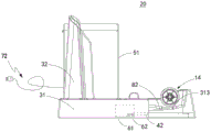
图7为图5所示的基站的主视半剖图;其中,外接口与流体连接器相接合,侧刷未被示出;Fig. 7 is a front half-sectional view of the base station shown in Fig. 5; wherein, the external interface is engaged with the fluid connector, and the side brush is not shown;
图8为图7所示A处的局部放大图。FIG. 8 is a partially enlarged view of the point A shown in FIG. 7 .
图中标注:Labeled in the figure:
100、表面清洁系统;10、表面清洁装置;20、基站;100. Surface cleaning system; 10. Surface cleaning device; 20. Base station;
1、清洁底座;11、座体;12、上盖;13、转体腔;131、下部开口;1. Clean base; 11. Base body; 12. Upper cover; 13. Swivel cavity; 131. Lower opening;
14、清洁部件;141、内腔;142、辊体;143、刷毛层;144、中轴;14. Cleaning parts; 141. Inner cavity; 142. Roller body; 143. Brush layer; 144. Central axis;
15、侧刷;16、抽吸嘴;15. Side brush; 16. Suction nozzle;
17、快拆部件;171、主体;172、转动件;173、销轴;174、腔室;17. Quick release parts; 171. Main body; 172. Rotating parts; 173. Pin shaft; 174. Chamber;
2、直立机体;21、连接端;22、主体部;23、手柄部;231、把手;232、控制器;2. Upright body; 21. Connecting end; 22. Main body; 23. Handle; 231. Handle; 232. Controller;
24、清洁液箱;25、污液箱;26、抽吸电机;27、可充电电池;28、接电端子;24. Cleaning liquid tank; 25. Dirty liquid tank; 26. Suction motor; 27. Rechargeable battery; 28. Electric terminal;
3、壳体;31、托盘;311、底部部分;312、外周壁;313、凹槽;32、台座;3. Shell; 31. Tray; 311. Bottom part; 312. Peripheral wall; 313. Groove; 32. Pedestal;
41、流体连接器;42、公用管道;41. Fluid connectors; 42. Public pipelines;
51、供给箱;52、供液泵;51. Supply box; 52. Liquid supply pump;
61、风扇组件;62、加热丝组件;61. Fan assembly; 62. Heating wire assembly;
71、电连接座;72、导电线;71. Electrical connection seat; 72. Conductive wire;
81、回收箱;82、回收通路。81. Recycling bin; 82. Recycling pathway.
具体实施方式Detailed ways
为详细说明本申请的技术内容、构造特征、所达成目的及功效,下面将结合本申请实施例中的附图,对本申请实施例中的技术方案进行描。In order to describe the technical content, structural features, achieved goals and effects of the present application in detail, the technical solutions in the embodiments of the present application will be described below in conjunction with the drawings in the embodiments of the present application.
本申请中,诸如“在……之下”、“在……下方”、“在……下”、 “下”、“在……上方”、“上”、“在……之上”、“较高的”、“侧”(例如,如在“侧壁”中)等的空间相对术语,由此来描述如附图中示出的一个元件与另一(其它)元件的关系。空间相对术语意图包括设备在使用、操作和/或制造中除了附图中描绘的方位之外的不同方位。例如,如果附图中的设备被翻转,则被描述为“在”其它元件或特征“下方”或“之下”的元件随后将被 定位为“在”所述其它元件或特征“上方”。因此,示例性术语“在……下方”可以包括上方和下方两种方位。此外,设备可以被另外定位(例如,旋转90度或者在其它方位处),如此,相应 地解释在此使用的空间相对描述语。In this application, such as "below...", "below...", "below...", "below", "above...", "on", "above...", The spatially relative terms of "higher", "side" (eg, as in "sidewall"), etc., thereby describe the relationship of one element to another (other) element as shown in the figures. Spatially relative terms are intended to encompass different orientations of the device in use, operation and/or manufacture in addition to the orientation depicted in the figures. For example, if the device in the figures is turned over, elements described as "below" or "beneath" other elements or features would then be oriented "above" the other elements or features. Thus, the exemplary term "below" can encompass both an orientation of above and below. Furthermore, the device may be otherwise positioned (e.g., rotated 90 degrees or at other orientations), and as such, the spatially relative descriptors used herein are interpreted accordingly.
图1示出了本发明所提供的表面清洁系统100,其包括表清洁装置10与独立于表面清洁装置10的基站20。表面清洁装置10可沿着待清洁表面移动并进行清洁作业,基站20可供表面清洁装置10放置且对表面清洁装置10的清洁部件14(见下文)进行清洁。FIG. 1 shows a
参阅图2-3,表面清洁装置10包括可沿待清洁表面移动的清洁底座1与可转动地连接于清洁底座1后部的直立机体2。Referring to FIGS. 2-3 , the
清洁底座1包括形成主体外轮廓的座体11、可拆卸地连接于座体11前部的上盖12、可转动地安装于座体11上的清洁部件14、与清洁部件14传动连接的侧刷15以及位于座体11内侧的抽吸嘴16。The
座体11与上盖12共同限定有一位于清洁底座1前部的转体腔13,转体腔13具有朝向待清洁表面的下部开口131。本实施例所提供的清洁部件14为一刷辊,该清洁部件14可转动地布置于转体腔13处并且该清洁部件14的部分外周表面穿过下部开口131,以接触待清洁表面。The
结合图4,清洁部件14包括内部具有空腔141的辊体142与覆盖于辊体142外周表面上的刷毛层143。辊体142包括相互远离的第一端部与第二端部并且开设有位于外周表面上的多个通孔(图中未标示出)。各通孔均与内腔141流体连通并供第一流体通路(见下文)向刷毛层143施加清洁液。由于该通孔位于刷毛层143的根部,在利用该通孔对清洁部件14进行清洁与吹干时(详见下文),清洁液与气流可直达刷毛层143的根部,从而获得较好的清洁效果。Referring to FIG. 4 , the
清洁底座1还布置有位于座体11内部的驱动电机(图中未标示出)与用于支撑侧刷15的快拆部件17。辊体142的第一端部与驱动电机传动连接,以使得驱动电机可驱动清洁部件14转动。The
快拆部件17可拆卸地安装于座体11的前部并位于转体腔13处。快拆部件17包括可拆卸地连接于座体11的主体171、可转动地布置于主体171侧部且朝向清洁部件14的转动件172以及中空的销轴173。The
辊体142的第二端部固定安装于快拆部件17的转动件172上。主体171限定有一半封闭的腔室174并开设有左右贯通的连接口(图中未标示出)。销轴173布置于该连接口处并固定设置于转动件172,可以理解地,清洁部件14、转动件172以及销轴173同步转动。The second end of the
侧刷15布置于主体171的腔室174内并包括刷体(图中未标示出)与固定连接于刷体上的多个刷毛簇(图中未标示出)。刷体固定支撑于快拆部件17的销轴173上并与该销轴173一同转动。多个刷毛簇可从腔室174径向或/和侧向对外伸出,以清洁相接触的待清洁表面。可以理解地,该侧刷15尤其适用于清洁墙角、桌角等处。The
结合图8,销轴173从侧刷15中部对外露出并形成供基站20上流体连接器41(见下文)对接的外接口(图中未标示出)。清洁部件14还布置有中空且沿着左右方向延伸的中轴144,中轴144固定设置于辊体142的第二端部处且接通销轴173。销轴173、中轴144以及内腔141依次流体连通,部分销轴173的内部与中轴144的内部形成与外接口接通的下游流道,该下游流道为第一流体通路(见下文)的一部分。Referring to FIG. 8 , the
直立机体2沿一纵向方向延伸,其包括靠近清洁底座1的连接端21、远离连接端21的手柄部23以及位于连接端21与手柄部23之间的主体部22。The upright body 2 extends along a longitudinal direction, and includes a
手柄部23包括使用用户握持的把手231与布置于该把手231上的控制器232,控制器232供用户控制表面清洁装置10工作。连接端21可转动地连接于清洁底座1的后部,便于供用户调节使用的角度以存放表面清洁装置10或手持把手231并推动清洁底座1在待清洁表面上移动。The handle part 23 includes a
主体部22上搭载有多个表面清洁装置10的工作部件,这些工作部件包括能够存储与提供清洁液的清洁液箱24、能够接收与存储污液的污液箱25、能够形成抽吸流的抽吸电机26以及可对外提供电能的可充电电池27。The
清洁液箱24可拆卸地安装于主体部22的顶部处,以便于用户向其添加清洁液。清洁液箱24与清洁部件14的内腔141流体连通并形成一条从清洁液箱24延伸至内腔141的第一流体通路(图中未标示出)。外接口与该第一流体通路接通并且二者的连接处将第一流体通路分成上游通路与下游通路。The cleaning
上游通路上还布置有一可选择性启动的供液泵(图中未示出),以选择性地将清洁液箱24内的清洁液输送至内腔141处或阻断清洁液箱24与内腔141之间的流体流动。进一步地,外接口上还布置有单向阀,该单向阀被配置成在自然状态下关闭以避免第一流体通路内的清洁液流出,以及在与流体连接器41对接时被打开以供基站20内的流体进入清洁部件14的内腔141。A selectively activated liquid supply pump (not shown in the figure) is also arranged on the upstream passage to selectively deliver the cleaning liquid in the cleaning
在其他实施例中,也可以取消侧刷,外接口直接与清洁部件的内腔相接通;亦可在清洁底座上布置朝向清洁部件且具有多个喷嘴的流体分配器,第一流体通路的末端与该流体分配器接通以相清洁部件分配清洁液,在该情况下,清洁部件也可为一个或多个左右排列的刷盘。在外接口与第一流体通路接通且该第一流体通路可向清洁部件分配清洁液的前提下,其具体的清洁部件的类型以及第一流体通路的路径设置不对本发明的保护范围起到限定作用。In other embodiments, the side brush can also be cancelled, and the external interface is directly connected to the inner cavity of the cleaning component; a fluid distributor facing the cleaning component and having multiple nozzles can also be arranged on the cleaning base, and the first fluid passage The end is connected with the fluid distributor for distributing cleaning fluid to the cleaning components. In this case, the cleaning components can also be one or more brush plates arranged left and right. On the premise that the external interface is connected to the first fluid passage and the first fluid passage can distribute cleaning liquid to the cleaning components, the specific type of cleaning components and the path setting of the first fluid passage do not limit the protection scope of the present invention effect.
抽吸电机26与清洁底座1的抽吸嘴16之间形成一条可供抽吸流流动的流体路径。当抽吸电机26启动时,抽吸流携带待清洁表面的污液经由转体腔13进入该流体路径。污液箱25布置于该流体路径上,以接收并储存由抽吸流携带而来的污液。A fluid path through which the suction flow can flow is formed between the
可充电电池27与表面清洁装置10的各个用电部件形成电连接,以向这些用电设备提供电能。直立机体2还布置有与可充电电池27电连接并对外露出的接电端子28,接电端子28能够为可充电电池27接入市电并进行充电。The
参阅图5-8,基站20包括壳体3、能够对清洁部件14进行清洗的清洗系统、能够向清洁部件14输送吹干空气的吹风系统、能够为可充电电池27进行充电的充电系统、能够回收污液的污液回收系统以及布置于壳体3内部的第二流体通路。5-8, the
壳体3包括设置于底部的托盘31与固定设置于托盘31上侧的台座32。托盘31被配置成适于容纳表面清洁装置10的清洁底座1,台座32大致沿着竖直方向延伸出并被配置成适于支撑直立机体2的后部。The
托盘31上具有可支撑清洁底座1的底部部分311以及沿着该底部部分311外边缘周向延伸的外周壁312。底部部分311的前部向下凹陷并形成一凹槽313,该凹槽313沿着左右方向延伸并被配置成适于容纳表面清洁装置10的清洁部件14。外周壁312相对底部部分311向上凸出,以将清洗清洁部件14时产生的污液限定于托盘31内。The
第二流体通路包括固定设置于外周壁312上的流体连接器41以及与该流体连接器41流体连通的公用管道42。公用管道42为一柔性软管,其布置于托盘31的内部并具有相互远离的第一端部(图中未标示出)与第二端部(图中未标示出)。流体连接器41上布置有相互连通的流体进口(图中未标示出)与流体出口(图中未标示出),其流体进口与公用管道42的第一端部相接通,以供流体通路内的流体流入流体连接器42;其流体出口被配置成当表面清洁装置10放置于基站20上时,该流体出口与表面清洁装置10的外接口相接通并打开外接口上的单向阀,以连接第二流体通路与第一流体通路。The second fluid passage includes a
清洗系统包括能够存储和对外提供清洗液的供给箱51以及与该供给箱51流体连通的供液泵52。供给箱51固定设置于壳体3的侧部。公用管道42的第二端部分叉并形成有两条相互独立的支路,其中一条支路接通供液泵52的出口。供液泵52位于壳体3的内侧并被配置成可选择性地启动,以选择性地将供给箱51内的清洗液输送至公用管道42内或阻断供给箱51与公用管道42之间的流体流动。The cleaning system includes a
吹风系统包括可向外吹出空气的风扇组件61与可对空气加热的加热丝组件62。风扇组件61与加热丝组件62均布置于托盘31的内部,加热丝组件62布置于吹风系统的出气端处。公用管道42第二端部的另一支路与该吹风系统的出气端相连接,以接通吹风系统与流体连接器41。The blowing system includes a
充电系统包括设置于台座32顶部的电连接座71以及与该电连接座71电连接的导电线72。当表面清洁装置10放置于基站20上时,台座32支撑直立机体2的后部,电连接座71与接电端子28对接并形成电连接,导电线72接入市电后即可对可充电电池27进行充电。The charging system includes an
污液回收系统包括能够接收以及储存污液的回收箱81、与该回收箱81流体连通的回收通路82以及位于回收通路82上的回收泵(图中未示出)。回收箱81固定设置于壳体3的侧部,回收通路82远离回收箱81的一侧端部与凹槽313流体连通。回收通路82同样由柔性管体构成,其独立于第二流体通路。回收泵被配置成可选择性地启动,以在基站20对清洁部件14进行清洁时回收凹槽313处的污液。The dirty liquid recovery system includes a
以下说明基站20的工作原理:当表面清洁装置10放置于基站20上时,清洁底座1支撑于基站20的底部部分311上,清洁部件14位于基站20的凹槽313处。表面清洁装置10的驱动电机启动并驱动清洁部件14转动;供液泵启动,供给箱51内的清洁液先后流经公用管道42、流体连接器41、第一流体通路以及内腔141并最后经由辊体142上的通孔到达清洁部件14的刷毛层143,以对清洁部件14进行清洗;回收泵启动,以回收凹槽313处的污液。在完成清洁部件14的清洗后,风扇组件61与加热丝组件62均启动,吹风系统产生的热气流先后流经公用管道42、流体连接器41、第一流体通路以及内腔141并最后经由辊体142上的通孔到达清洁部件14的刷毛层143,以吹干清洁部件14。The working principle of the
从上可以看出,由于借用了部分的第一流体通路,基站20上不必布置喷头等部件以引导清洁液流向清洁部件14,从而简化了基站20的结构并减少了制造成本。此外,通过集成式的第二流体通路,减少了基站20内的管道布置,进一步简化了基站20的结构并减少了基站20的体积,便于用户收纳该基站。It can be seen from the above that due to borrowing part of the first fluid passage, there is no need to arrange nozzles and other components on the
需要说明的是,本实施例所提供的直立式表面清洁装置10仅为非限定性示例。在其他实施例中,也可采用自移动式表面清洁装置,即清洁机器人。可以理解地,在基站的托盘形状和充电座位置做出适应性变化后,即可具备上述所有的基站功能。It should be noted that the upright
上述实施例只为说明本申请的技术构思及特点,其目的在于让熟悉此项技术的人士能够了解本申请的内容并据以实施,并不能以此限制本申请的保护范围。凡根据本申请精神所作的等效变化或修饰,都应涵盖在本申请的保护范围之内。The above-mentioned embodiments are only to illustrate the technical concept and characteristics of the present application, and the purpose is to enable those familiar with this technology to understand the content of the present application and implement it accordingly, and not to limit the protection scope of the present application. All equivalent changes or modifications made according to the spirit of the application shall fall within the protection scope of the application.
Claims (10)
Priority Applications (1)
| Application Number | Priority Date | Filing Date | Title |
|---|---|---|---|
| CN202211417903.0A CN115778258B (en) | 2022-11-14 | 2022-11-14 | Surface cleaning system |
Applications Claiming Priority (1)
| Application Number | Priority Date | Filing Date | Title |
|---|---|---|---|
| CN202211417903.0A CN115778258B (en) | 2022-11-14 | 2022-11-14 | Surface cleaning system |
Publications (2)
| Publication Number | Publication Date |
|---|---|
| CN115778258A true CN115778258A (en) | 2023-03-14 |
| CN115778258B CN115778258B (en) | 2025-11-25 |
Family
ID=85437268
Family Applications (1)
| Application Number | Title | Priority Date | Filing Date |
|---|---|---|---|
| CN202211417903.0A Active CN115778258B (en) | 2022-11-14 | 2022-11-14 | Surface cleaning system |
Country Status (1)
| Country | Link |
|---|---|
| CN (1) | CN115778258B (en) |
Cited By (1)
| Publication number | Priority date | Publication date | Assignee | Title |
|---|---|---|---|---|
| WO2025139792A1 (en) * | 2023-12-29 | 2025-07-03 | 深圳洛克创新科技有限公司 | Base and cleaning system |
Citations (6)
| Publication number | Priority date | Publication date | Assignee | Title |
|---|---|---|---|---|
| CA3123772A1 (en) * | 2018-06-22 | 2019-12-26 | Bissell Inc. | Surface cleaning apparatus and tray |
| CN212939601U (en) * | 2020-05-20 | 2021-04-13 | 深圳市杉川机器人有限公司 | cleaning device |
| CN113243843A (en) * | 2021-02-10 | 2021-08-13 | 北京顺造科技有限公司 | Base station, surface cleaning system and cleaning, drying and disinfecting method of surface cleaning equipment |
| CN113796796A (en) * | 2021-09-28 | 2021-12-17 | 深圳市杉川机器人有限公司 | Floor brush and floor washing machine |
| CN113854908A (en) * | 2021-09-30 | 2021-12-31 | 易宝软件有限公司 | Self-cleaning method of floor cleaning machine, electronic equipment and computer storage medium |
| CN216364947U (en) * | 2021-09-29 | 2022-04-26 | 深圳市杉川机器人有限公司 | Charging seat of floor cleaning machine and floor cleaning machine assembly with charging seat |
-
2022
- 2022-11-14 CN CN202211417903.0A patent/CN115778258B/en active Active
Patent Citations (6)
| Publication number | Priority date | Publication date | Assignee | Title |
|---|---|---|---|---|
| CA3123772A1 (en) * | 2018-06-22 | 2019-12-26 | Bissell Inc. | Surface cleaning apparatus and tray |
| CN212939601U (en) * | 2020-05-20 | 2021-04-13 | 深圳市杉川机器人有限公司 | cleaning device |
| CN113243843A (en) * | 2021-02-10 | 2021-08-13 | 北京顺造科技有限公司 | Base station, surface cleaning system and cleaning, drying and disinfecting method of surface cleaning equipment |
| CN113796796A (en) * | 2021-09-28 | 2021-12-17 | 深圳市杉川机器人有限公司 | Floor brush and floor washing machine |
| CN216364947U (en) * | 2021-09-29 | 2022-04-26 | 深圳市杉川机器人有限公司 | Charging seat of floor cleaning machine and floor cleaning machine assembly with charging seat |
| CN113854908A (en) * | 2021-09-30 | 2021-12-31 | 易宝软件有限公司 | Self-cleaning method of floor cleaning machine, electronic equipment and computer storage medium |
Cited By (1)
| Publication number | Priority date | Publication date | Assignee | Title |
|---|---|---|---|---|
| WO2025139792A1 (en) * | 2023-12-29 | 2025-07-03 | 深圳洛克创新科技有限公司 | Base and cleaning system |
Also Published As
| Publication number | Publication date |
|---|---|
| CN115778258B (en) | 2025-11-25 |
Similar Documents
| Publication | Publication Date | Title |
|---|---|---|
| US20240172915A1 (en) | Robot base station, robot system, base module, and functional parts of base station | |
| CN113243856B (en) | Base station equipment with storage device and surface cleaning system | |
| CN103445720A (en) | Surface cleaning apparatus | |
| CN116035483A (en) | Surface cleaning system | |
| WO2025138945A1 (en) | Docking station and cleaning system | |
| TW202239365A (en) | Cleaner | |
| CN115444331B (en) | Cleaning base and cleaning system | |
| CN115778258A (en) | Surface cleaning system | |
| CN113243849A (en) | Cleaning device, supply device and cleaning system | |
| CN115227152B (en) | Base station of floor cleaning device and cleaning system | |
| CN218500643U (en) | Clean basic station | |
| CN115349784A (en) | Surface cleaning device and surface cleaning equipment | |
| WO2023019968A1 (en) | Cleaning apparatus | |
| TWM669849U (en) | Pile body and cleaning system | |
| TWM672541U (en) | Docking station and cleaning system | |
| CN220212837U (en) | Base station and cleaning system for floor scrubber | |
| CN115644747A (en) | Base station and surface cleaning system | |
| CN115844277A (en) | Surface cleaning system | |
| CN217244155U (en) | Wet surface cleaning system | |
| CN216147982U (en) | Water tank and cleaning equipment | |
| CN116274054B (en) | Surface cleaning systems | |
| WO2022267411A1 (en) | Cleaning base and cleaning system | |
| CN221813846U (en) | Cleaning systems, cleaning equipment and piles | |
| CN214856439U (en) | A multifunctional supply base for a floor scrubbing device | |
| CN214906456U (en) | A supply structure for a floor scrubbing device |
Legal Events
| Date | Code | Title | Description |
|---|---|---|---|
| PB01 | Publication | ||
| PB01 | Publication | ||
| SE01 | Entry into force of request for substantive examination | ||
| SE01 | Entry into force of request for substantive examination | ||
| GR01 | Patent grant | ||
| GR01 | Patent grant |