Disclosure of Invention
In view of the above, it is desirable to provide a heating element, an atomizer, an electronic atomizing device and a manufacturing method thereof, which can improve the liquid storage effect.
To achieve the above object, one aspect of the present application provides a heat generating component, including:
a first substrate formed with a middle passage;
the second base body is provided with an accommodating channel, the first base body is accommodated in the accommodating channel, a spacing space is arranged between the outer peripheral surface of the first base body and the wall surface of the accommodating channel, the spacing space is empty or filled with a porous piece, one of the wall surface of the middle channel and the outer peripheral surface of the second base body is a heating surface, and the other one of the wall surface of the middle channel and the outer peripheral surface of the second base body is a liquid inlet surface.
In some embodiments, the first base is formed with a plurality of overflow holes communicating the intermediate passage and the spacing space, and the second base is formed with a plurality of communication holes communicating the spacing space and an outer circumferential surface of the second base.
In some embodiments, the area of the flow cross section of the overflowing hole is not equal to the area of the flow cross section of the communicating hole.
In some embodiments, the diameter of the overflowing hole is not equal to the diameter of the communicating hole.
In some embodiments, the wall surface of the intermediate channel is the heating surface, the outer peripheral surface of the second substrate is the liquid inlet surface, and the diameter of the overflowing hole is smaller than that of the communicating hole; or,
the wall surface of the middle channel is the liquid inlet surface, the peripheral surface of the second base body is the heating surface, and the aperture of the overflowing hole is larger than that of the communicating hole.
In some embodiments, the porosity of the first substrate is not equal to the porosity of the second substrate.
In some embodiments, the wall surface of the intermediate channel is the heat-generating surface, the outer circumferential surface of the second substrate is the liquid inlet surface, and the porosity of the first substrate is smaller than that of the second substrate; or,
the wall surface of the middle channel is the liquid inlet surface, the peripheral surface of the second base body is the heating surface, and the porosity of the first base body is larger than that of the second base body.
In some embodiments, an aperture of the overflow hole penetrating through the outer peripheral surface of the first base body is an overflow opening, an aperture of the communication hole penetrating through the wall surface of the accommodation channel is a communication opening, and a projection of the communication opening on the first base body at most partially overlaps with the overflow opening.
In some embodiments, a distance between an upper end of the outer peripheral surface of the first base and an upper end of the wall surface of the accommodation channel is larger than a distance between a lower end of the outer peripheral surface of the first base and a lower end of the wall surface of the accommodation channel.
In some embodiments, the distance between the outer peripheral surface of the first base and the wall surface of the accommodating passage gradually increases from top to bottom.
In some embodiments, the first substrate has a cylindrical or truncated conical profile.
In some embodiments, the second substrate has a profile shape of a cylinder or a truncated cone.
In some embodiments, the heat generating component includes a plurality of heat generating films, and the plurality of heat generating films are arranged on the heat generating surface at intervals.
In some embodiments, the porous member is a ceramic porous structure.
The present application provides an atomizer comprising:
a reservoir for storing a liquid substrate to be atomized;
in the above heating assembly, the liquid substrate in the liquid storage container can flow to the liquid inlet surface.
Another aspect of the present application provides an electronic atomization device, including:
the atomizer described above;
and the power supply part is electrically connected with the heating component.
In some embodiments, the electronic atomization device comprises an air inlet channel and an air outlet channel which are both communicated with the outside, and the heating component is positioned between the air inlet channel and the air outlet channel;
the middle channel is communicated with the air inlet channel and the air outlet channel; the peripheral surface of the second base body is a part of the wall surface of an airflow channel of the electronic atomization device, and the airflow channel is communicated with the air inlet channel and the air outlet channel.
The present application also provides a manufacturing method for manufacturing a heat generating component including a first base body formed with an intermediate passage and a second base body; the second base body is formed with a housing passage in which the first base body is housed, a space is provided between an outer peripheral surface of the first base body and a wall surface of the housing passage, the space is empty or filled with a porous member, one of the wall surface of the intermediate passage and the outer peripheral surface of the second base body is a heat generation surface, and the other of the wall surface of the intermediate passage and the outer peripheral surface of the second base body is a liquid intake surface, the manufacturing method including:
fabricating a first reverse mold nested with the structure of the first substrate and a second reverse mold nested with the structure of the second substrate;
sleeving the first reverse mold in the second reverse mold, and placing a breaking mold between the first reverse mold and the second reverse mold, wherein the first reverse mold, the second reverse mold and the breaking mold are all placed in an outer mold to jointly define a mold cavity;
filling the mold cavity with a slurry to form a green body;
processing the green body to form the first substrate and the second substrate.
In some embodiments, the method of manufacturing comprises:
manufacturing a first master mold having the same structure as the first base and a second master mold having the same structure as the second base, manufacturing the first reverse mold from the first master mold and manufacturing the second reverse mold from the second master mold.
In some embodiments, after processing the green body to form the first substrate and the second substrate, the method of manufacturing comprises:
and coating or brushing a film on the heating surface to form a heating film.
In some embodiments, the first reverse mold is a soft material and/or the first reverse mold is a disposable sacrificial mold.
In some embodiments, the second reverse mold is a soft material and/or the second reverse mold is a disposable sacrificial mold.
In some embodiments, the first base is formed with a plurality of overflow holes, the second base is formed with a plurality of communication holes, the overflow holes communicate the intermediate channel and the spaced space, the communication holes communicate the spaced space and an outer circumferential surface of the second base, the first reverse mold has a first pillar nested with the overflow holes, and the second reverse mold has a second pillar nested with the communication holes.
In some embodiments, fabricating a first inverse nested with the structure of the first substrate and a second inverse nested with the structure of the second substrate comprises:
manufacturing a first soft template and a second soft template respectively, wherein the first soft template comprises a first flat plate and a plurality of first stand columns positioned on the first flat plate, and the second soft template comprises a second flat plate and a plurality of second stand columns positioned on the second flat plate;
and winding the first flat plate into a hollow circular ring structure to form the first reverse mold, and winding the second flat plate into a hollow circular ring structure to form the second reverse mold, wherein the first upright is towards the outer side, and the second upright is towards the inner side.
In some embodiments, the first soft template is formed by integral injection molding; and/or the presence of a gas in the gas,
and forming the second soft template through integral injection molding.
The heating assembly that this application embodiment provided, the liquid matrix that comes from into the liquid level passes through the interstitial space water conservancy diversion to the heating surface, and the interstitial space can play the effect of water conservancy diversion and the liquid matrix of keeping in. Spacing space is vacant or fill porous piece and make liquid matrix can be followed the feed liquor face and introduced to the face that generates heat, and spacing space is vacant can improve the liquid storage volume by great degree, and porous piece can improve the lock liquid ability, plays the effect of slowly-releasing, further the velocity of flow of balanced liquid matrix for liquid matrix releases to the face that generates heat more balancedly. The spacing space can store a certain amount of liquid matrix, and along with the liquid matrix on the heating surface evaporates gradually, the liquid matrix in the spacing space can in time supply to the heating surface, avoids the heating surface to take place the phenomenon of dry combustion to a certain extent.
Detailed Description
It should be noted that the embodiments and technical features of the embodiments in the present application may be combined with each other without conflict, and the detailed description in the detailed description should be understood as an explanation of the gist of the present application and should not be construed as an undue limitation to the present application.
The directional terms in the embodiments of the present application are used for convenience in describing the present application and for simplicity in description, and do not indicate or imply that the referenced device or element must have a particular orientation, be constructed and operated in a particular orientation, and thus should not be construed as limiting the present application. The present application will now be described in further detail with reference to the accompanying drawings and specific examples.
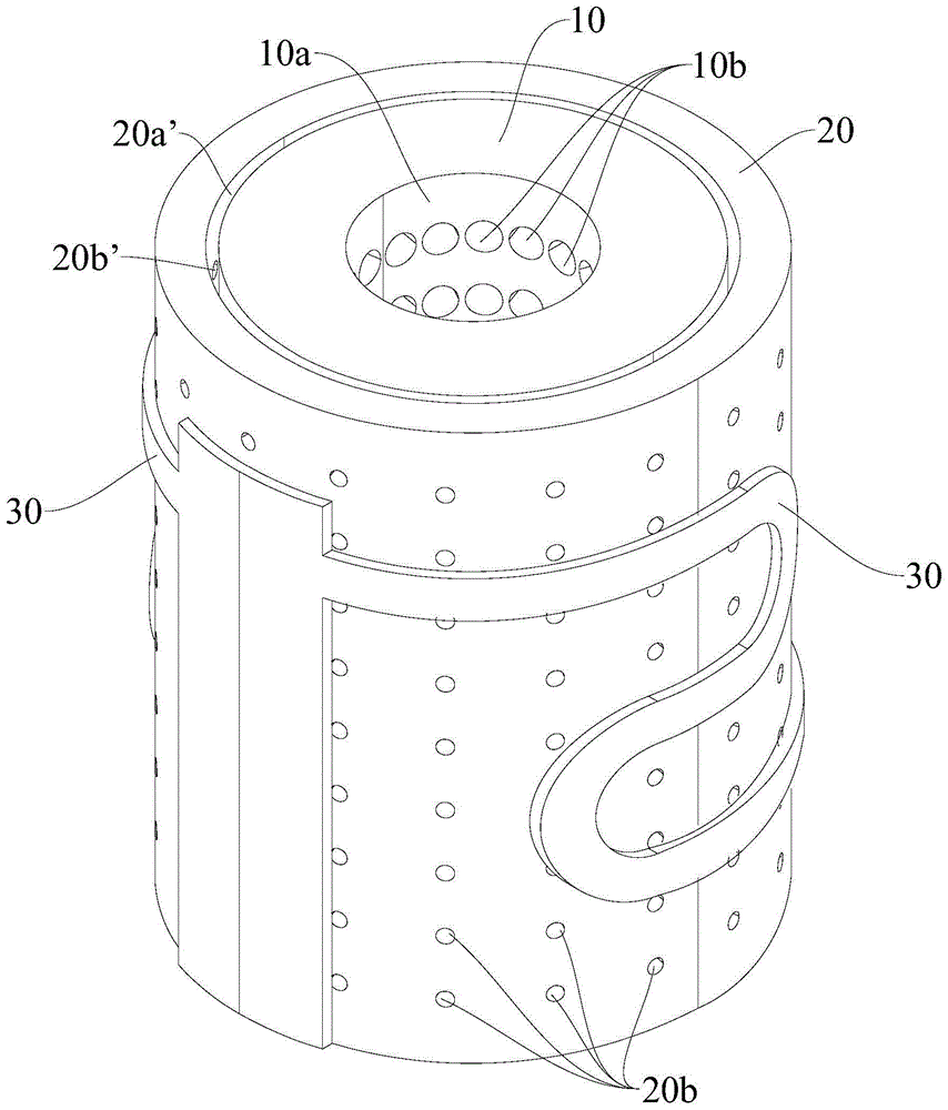
Referring to fig. 1 to 5 and fig. 11, according to an aspect of the present invention, a heat generating element is provided, which includes a first substrate 10 and a second substrate 20.
The first base body 10 is formed with an intermediate passage 10a. Specifically, the intermediate passage 10a extends in the height direction of the first base 10.
The second base body 20 is formed with a receiving passage 20a. Specifically, the accommodation channel 20a extends in the height direction of the second substrate 20. Note that the height direction of the first substrate 10 and the height direction of the second substrate 20 are aligned.
The first base body 10 is accommodated in the accommodating passage 20a, and a space 20a 'is provided between the outer peripheral surface of the first base body 10 and the wall surface of the accommodating passage 20a, and the space 20a' is empty or filled with a porous member. Referring to fig. 5, the empty space means that no solid structure is disposed in the space 20a ', that is, the space 20a' is filled with air. The porous member refers to a structure having a plurality of pores therein communicating with each other and with the surface of the material. That is, the space 20a 'may not be filled with a solid structure or a porous member, so that the space 20a' is empty or the holes in the porous member are used to temporarily store the liquid substrate and to facilitate the circulation of the liquid substrate.
One of the wall surface of the intermediate passage 10a and the outer peripheral surface of the second base 20 is a heat generation surface, and the other of the wall surface of the intermediate passage 10a and the outer peripheral surface of the second base 20 is a liquid inlet surface. For example, if the wall surface of the intermediate passage 10a is a heat generating surface, the outer peripheral surface of the second substrate 20 is a liquid inlet surface. For example, when the outer peripheral surface of the second base 20 is a heat generating surface, the wall surface of the intermediate passage 10a is a liquid inlet surface. The liquid inlet surface is the surface for receiving the liquid substrate, and the heat emitting surface is the surface for heating the liquid substrate. The liquid medium from the inlet surface is guided through the first substrate 10, the interspace 20a' and the second substrate 20 to the heating surface.
According to the heating assembly provided by the embodiment of the application, the liquid matrix from the liquid inlet surface is guided to the heating surface through the separation space 20a ', and the separation space 20a' can play a role in guiding and temporarily storing the liquid matrix. The spacing space 20a 'is empty or is filled with the porous piece, so that the liquid matrix can be guided to the heating surface from the liquid inlet surface, the spacing space 20a' is empty, the liquid storage capacity can be greatly improved, the liquid locking capacity can be improved through the porous piece, the slow release effect is achieved, the flow rate of the liquid matrix is further balanced, and the liquid matrix is more uniformly released to the heating surface. The spacing space 20a 'can store a certain amount of liquid matrix, and along with the gradual evaporation of the liquid matrix on the heating surface, the liquid matrix in the spacing space 20a' can be supplemented to the heating surface in time, so that the phenomenon that the heating surface is dried to burn is avoided to a certain extent.
Both the first substrate 10 and the second substrate 20 may be in fluid communication with a liquid matrix. Referring to fig. 5, the first base 10 is formed with a plurality of overflow holes 10b, and the second base 20 is formed with a plurality of communication holes 20b. The overflowing hole 10b communicates the intermediate passage 10a and the space 20a'. The communication hole 20b communicates the space 20a' with the outer peripheral surface of the second base 20. In this way, the liquid matrix can flow between the intermediate passage 10a and the outer peripheral surface of the second substrate 20 through the flow-through holes 10b, the spacing spaces 20a', and the communication holes 20b. Illustratively, the overflow holes 10b penetrate the first base body 10 in the thickness direction of the first base body 10. That is, the overflow hole 10b communicates the intermediate passage 10a and the outer peripheral surface of the first base body 10. The communication hole 20b penetrates the second base body 20 in the thickness direction of the second base body 20. That is, the communication hole 20b communicates the accommodating passage 20a and the outer circumferential surface of the second base 20. The liquid substrate from the liquid inlet surface is guided to the heat generating surface through the overflowing hole 10b, the spacing space 20a' and the communicating hole 20b.
In this embodiment, the liquid substrate from the liquid inlet surface is guided to the heat generating surface through the overflowing holes 10b, the separation spaces 20a 'and the communication holes 20b, and the overflowing holes 10b, the separation spaces 20a' and the communication holes 20b can play a role in guiding and temporarily storing the liquid substrate. The overflowing hole 10b, the interval space 20a 'and the communicating hole 20b can store a certain amount of liquid substrate, and as the liquid substrate on the heating surface gradually evaporates, the liquid substrate in the overflowing hole 10b, the interval space 20a' and the communicating hole 20b can be timely supplemented to the heating surface.
In the present embodiment, the plurality of the fingers includes two and more than two.
The heating element that this application embodiment provided can be used to the atomizer, and the atomizer includes the heating element in stock solution container and this application any one embodiment, and stock solution container is used for storing the liquid matrix that treats the atomizing. The liquid substrate in the reservoir is able to flow to the inlet face 10a.
Referring to fig. 6, the heating element provided in the embodiment of the present application may be used in an electronic atomization device 100. The electronic atomizer 100 includes an atomizer according to any of the embodiments of the present application, and a power supply unit electrically connected to the heat generating component. The power supply part is electrically connected with the heating component. The power supply unit is capable of supplying power to the heat generating component so that the heat generating component heats the liquid substrate.
The electronic atomization device 100 may be an electronic cigarette. That is, the liquid substrate may be tobacco tar.
For example, the electronic atomization device 100 may have a substantially elongated profile. In this way, the user can conveniently take the electronic atomization device 100.
The power supply unit includes, but is not limited to, a battery or the like capable of supplying power.
The heating assembly may heat the liquid substrate to a vapor state. For example, the heating assembly may heat and atomize the tobacco tar into an aerosol.
The electronic atomization device 100 that this application embodiment provided, interstitial space 20a 'is vacant or fill porous piece and make liquid matrix can be followed the inlet surface and led into to the face that generates heat, and interstitial space 20a' is vacant can improve the liquid storage capacity to a great extent, and porous piece can improve the lock liquid ability, plays the effect of slowly-releasing, further balances the velocity of flow of liquid matrix for liquid matrix releases to the face that generates heat more balancedly. The overflowing holes 10b, the spacing spaces 20a 'and the communicating holes 20b can store a certain amount of liquid matrix, along with the gradual evaporation of the liquid matrix on the heating surface, the liquid matrix in the overflowing holes 10b, the spacing spaces 20a' and the communicating holes 20b can be timely supplemented to the heating surface, the phenomenon that the heating surface is dried to burn is avoided to a certain extent, and the user experience can be effectively improved.
In some embodiments, the plurality of pores of the porous member may be in a disordered arrangement. That is, the holes in the porous member are randomly generated.
The porous member is not limited to be made of polymer.
Illustratively, in one embodiment, the porous member is a ceramic porous structure. That is, the porous member has a porous structure made of a ceramic material.
For example, the porous member may be formed by sintering the components such as aggregate, binder, and pore former at a high temperature. During the sintering process of the porous member, the pore-forming agent generates randomly arranged pores in the porous member.
In one embodiment, the intermediate passage 10a extends through both end surfaces of the first base 10 in the height direction.
In one embodiment, the receiving channel 20a penetrates both end surfaces of the second substrate 20 in the height direction.
In some embodiments, the plurality of flow holes 10b of the first substrate 10 are arranged in an ordered arrangement. That is, the plurality of overflowing holes 10b are arranged according to a set rule. In other words, the setting rule of the plurality of overflowing holes 10b can be artificially designed or controlled. Ordered arrangements include, but are not limited to, array arrangements. For example, in one embodiment, the plurality of overflowing holes 10b may be arranged in a one-dimensional array, that is, the plurality of overflowing holes 10b are arranged at intervals in one direction. In one embodiment, the plurality of overflowing holes 10b can be arranged in a two-dimensional array, that is, the plurality of overflowing holes 10b are arranged at intervals in two or more intersecting directions.
In some embodiments, the plurality of communicating pores 20b of the second substrate 20 are arranged in an orderly manner. That is, the plurality of communication holes 20b are arranged in accordance with a set rule. In other words, the setting rule of the plurality of communication holes 20b may be artificially designed or controlled. Ordered arrangements include, but are not limited to, array arrangements. For example, in one embodiment, the plurality of communication holes 20b may be arranged in a one-dimensional array, that is, the plurality of communication holes 20b are arranged at intervals in one direction. In one embodiment, the plurality of communication holes 20b may be arranged in a two-dimensional array, i.e., the plurality of communication holes 20b are arranged at intervals in two intersecting directions.
The first substrate 10 and the second substrate 20 may also be porous structures having a plurality of pores therein communicating with each other and with the surface of the material. The holes in the first substrate 10 and the holes in the second substrate 20 may be in a disordered arrangement. The holes in the first substrate 10 and the holes in the second substrate 20 have a capillary action such that liquid medium from the liquid inlet flows through the holes in the first substrate 10, the interspace 20a' and the holes in the second substrate 20 to the heat generating surface.
The material of the first substrate 10 and the second substrate 20 is not limited, and for example, the first substrate 10 and the second substrate 20 may be made of a dense ceramic material or a porous ceramic material.
In one embodiment, the area of the flow cross section of the overflowing hole 10b is not equal to that of the communicating hole 20b. The flow cross-section is the cross-section orthogonal to the flow stream or total flow, i.e. all flow lines of the liquid matrix, i.e. the plane perpendicular to the flow velocity cluster. The size of the area of the overflowing section is in positive correlation with the flow velocity of the liquid matrix, the area of the overflowing section of the overflowing hole 10b is not equal to the area of the overflowing section of the communicating hole 20b, so that the flow velocity of the liquid matrix flowing through the overflowing hole 10b is not equal to the flow velocity of the liquid matrix flowing through the communicating hole 20b, the liquid supply capacity can be improved, and the reverse gas can be reduced. The reverse gas refers to the liquid substrate forming aerosol after atomization and backflushing to the heating component, such as impacting the overflowing hole 10b and/or the communicating hole 20b and the like.
The cross-sectional shape of the overflowing hole 10b is not limited, and exemplary cross-sectional shapes of the overflowing hole 10b include, but are not limited to, a circle, an ellipse, a polygon, and the like. The polygon may be a quadrilateral, a pentagon or a special shape.
The cross-sectional shape of the communication hole 20b is not limited, and exemplary cross-sectional shapes of the communication hole 20b include, but are not limited to, a circle, an ellipse, a polygon, or the like. The polygon may be a quadrilateral, a pentagon or a special shape.
In one embodiment, the overflowing hole 10b can be a straight hole. That is, the single overflowing hole 10b extends in a straight line. Thus, the overflowing hole 10b is easy to form and low in manufacturing difficulty.
In one embodiment, the overflowing hole 10b is a constant diameter hole. That is, the hole diameter is equal at any position of the single overflowing hole 10 b.
In one embodiment, the communication hole 20b may be a straight hole. That is, the single communication hole 20b extends in a straight line. Thus, the communication hole 20b is easily molded and the manufacturing difficulty is low.
In one embodiment, the communication hole 20b is a constant diameter hole. That is, the hole diameters at arbitrary positions of the single communication holes 20b are equal.
In one embodiment, referring to fig. 4 and 5, the aperture of the overflowing hole 10b is not equal to the aperture of the communicating hole 20b. Illustratively, the cross-sectional shape of the overflowing hole 10b and the cross-sectional shape of the communicating hole 20b are both circular. The size of aperture and the cross section of overflowing are positive correlation, and the aperture of the discharge orifice 10b is unequal with the aperture of the intercommunicating pore 20b for the velocity of flow that liquid matrix flows through the discharge orifice 10b is unequal with the velocity of flow that liquid matrix flows through the intercommunicating pore 20b, so, not only can improve the liquid supply capacity, but also can reduce the blowback.
In one embodiment, the wall surface of the middle channel 10a is a heat generating surface, the outer peripheral surface of the second substrate 20 is a liquid inlet surface, and the aperture of the overflow hole 10b is smaller than that of the communication hole 20b. That is, the liquid substrate from the outer peripheral surface of the second substrate 20 flows through the communication holes 20b, the partition space 20a', and the overflowing hole 10b in this order, and then is introduced into the wall surface of the intermediate passage 10a, and atomized into aerosol on the wall surface of the intermediate passage 10a. The hole diameter of the communication hole 20b is relatively large, which facilitates rapid entry of the liquid matrix on the outer circumferential surface of the second substrate 20 into the communication hole 20b. The aperture of the overflowing hole 10b is relatively small, so that the difficulty of the aerosol in the middle channel 10a to rush back to the overflowing hole 10b is increased, the resistance is increased, and the reverse gas is reduced.
In one embodiment, referring to fig. 1 and 4, the wall surface of the middle channel 10a is a liquid inlet surface, the outer circumferential surface of the second substrate 20 is a heat generating surface, and the aperture of the overflowing hole 10b is larger than the aperture of the communicating hole 20b. That is, the liquid substrate from the wall surface of the intermediate passage 10a flows through the flow hole 10b, the space 20a', and the communication hole 20b in this order, and then is introduced into the outer peripheral surface of the second substrate 20, and atomized into aerosol on the outer peripheral surface of the second substrate 20. The flow-through holes 10b have a relatively large diameter, which facilitates rapid entry of the liquid medium on the wall of the intermediate channel 10a into the flow-through holes 10 b. The aperture of the communicating hole 20b is relatively small, increasing the difficulty of the aerosol on the outer peripheral surface of the second substrate 20 to return to the communicating hole 20b, increasing the resistance and reducing the back gas.
In one embodiment, referring to fig. 1, the porosity of the first substrate 10 is not equal to the porosity of the second substrate 20. The porosity is positively correlated with the flow rate of the liquid matrix, and the porosity of the first matrix 10 is not equal to the porosity of the second matrix 20, so that the flow rate of the liquid matrix flowing through the first matrix 10 is not equal to the flow rate of the liquid matrix flowing through the second matrix 20, thereby improving the liquid supply effect, realizing balanced liquid supply and reducing reverse gas.
In one embodiment, the wall surface of the middle channel 10a is a heat generating surface, the outer peripheral surface of the second substrate 20 is a liquid inlet surface, and the porosity of the first substrate 10 is smaller than the porosity of the second substrate 20. That is, the liquid substrate from the outer peripheral surface of the second substrate 20 flows through the communication holes 20b, the partition space 20a', and the overflowing hole 10b in this order, and then is introduced into the wall surface of the intermediate passage 10a, and atomized into aerosol on the wall surface of the intermediate passage 10a. The porosity of the second substrate 20 is relatively large, which facilitates rapid replenishment of the liquid matrix into the interstitial spaces 20a'. The porosity of the first substrate 10 is relatively small, reducing the chance of aerosol in the intermediate channel 10a rushing back into the spacing space 20a', increasing the resistance, and reducing the back gas.
In one embodiment, referring to fig. 1 and 4, the wall surface of the middle channel 10a is a liquid inlet surface, the outer peripheral surface of the second substrate 20 is a heat generating surface, and the porosity of the first substrate 10 is greater than that of the second substrate 20. That is, the liquid substrate on the wall surface of the intermediate passage 10a flows through the flow holes 10b, the space 20a', and the communication holes 20b in this order, and then is introduced into the outer peripheral surface of the second base 20, and is atomized into aerosol on the outer peripheral surface of the second base 20. The porosity of the first substrate 10 is relatively large, which facilitates rapid replenishment of the liquid matrix into the interstitial spaces 20a'. The porosity of the second substrate 20 is relatively small, so that the probability that the aerosol on the outer peripheral surface of the second substrate 20 is flushed back to the spacing space 20a' is reduced, the resistance is increased, and the reverse gas is reduced.
In one embodiment, an opening of the overflowing hole 10b penetrating through the outer peripheral surface of the first base body 10 is a overflowing opening, an opening of the communication hole 20b penetrating through the wall surface of the accommodating channel 20a is a communication opening 20b ', and a projection of the communication opening 20b' on the first base body 10 at most partially overlaps with the overflowing opening. For example, the projection of the communication port 20b' on the first substrate 10 and the flow-through port may partially overlap. For another example, the projection of the communication port 20b 'on the first substrate 10 does not overlap the flow-through port, that is, the projection of the communication port 20b' on the first substrate 10 is completely shifted from the flow-through port. By such a design, even if a trace amount of aerosol enters the overflowing hole 10b or the communicating hole 20b, since the projection of the communicating hole 20b 'on the first substrate 10 is at most partially overlapped with the overflowing hole, the trace amount of aerosol in the overflowing hole 10b or the communicating hole 20b is difficult to directly flow between the communicating hole 20b' and the overflowing hole, so that the difficulty of aerosol flowing is further increased, and the back gas is reduced.
In one embodiment, the interval between the upper end of the outer circumferential surface of the first base 10 and the upper end of the wall surface of the receiving passage 20a is greater than the interval between the lower end of the outer circumferential surface of the first base 10 and the lower end of the wall surface of the receiving passage 20a. That is, the height direction of the first base 10 may be set in the up-down direction, and the space between the upper end of the outer circumferential surface of the first base 10 and the upper end of the wall surface of the accommodating passage 20a is larger, the volume of the upper portion of the spacing space 20a' is larger, and more liquid medium can be accommodated; the lower end of the outer circumferential surface of the first substrate 10 and the lower end of the wall surface of the receiving passage 20a are spaced apart a small distance, and the lower portion of the space 20a ' has a small volume and receives a relatively small amount of the liquid medium, and thus the upper portion of the space 20a ' has a higher capillary force than the lower portion of the space 20a ' against the action of gravity.
In one embodiment, the distance between the outer circumferential surface of the first base 10 and the wall surface of the accommodating passage 20a gradually increases from top to bottom. The smaller the distance, the stronger the capillary action is, the distance is gradually increased from top to bottom, and the capillary action generated by the distance is gradually reduced from top to bottom, so that the capillary action in the spacing space 20a 'is gradually reduced from top to bottom, the effect of resisting gravity is better, the liquid matrix can be more uniformly distributed in the spacing space 20a', and the atomization effect is better.
The outline shape of the first substrate 10 may be a rotator structure. In one embodiment, referring to fig. 1, the first substrate 10 has a cylindrical or truncated conical shape. The contour shape of the first substrate 10 refers to an outer contour shape of the first substrate 10 in a multi-dimensional space.
The outline shape of the second substrate 20 may be a rotator structure. In one embodiment, referring to fig. 1, the second substrate 20 has a cylindrical or truncated cone shape. The contour shape of the second substrate 20 refers to the outer contour shape of the second substrate 20 in a multi-dimensional space.
For example, in some embodiments, the first substrate 10 and the second substrate 20 may be both cylindrical. In other embodiments, the first substrate 10 and the second substrate 20 may be both truncated cones. In still other embodiments, one of the first substrate 10 and the second substrate 20 has a cylindrical shape, and the other of the first substrate 10 and the second substrate 20 has a truncated cone shape.
In some embodiments, the outer contour of the first substrate 10 may also be truncated.
In some embodiments, the outer contour of the second substrate 20 may also be truncated.
In some embodiments, the heat generating component may be provided with a heat generating film 30 on the heat generating surface. Thus, the structure is simple, and the electrical connection between the power supply member and the heating film 30 is easily achieved. The heating film 30 is used for heating the liquid substrate on the heating surface after being electrified. For example, the heat generating film 30 may heat atomize the liquid substrate into an aerosol.
In some embodiments, the heat generating film 30 includes a positive electrode, a negative electrode and a resistance part, the positive electrode and the negative electrode are spaced apart, and the resistance part electrically connects the positive electrode and the negative electrode. The positive electrode and the negative electrode are respectively used for being connected with a positive terminal and a negative terminal of the power supply member. Illustratively, the positive electrode and the negative electrode are arranged at intervals along the circumferential direction, the resistance part is in a continuous bending structure, one end of the resistance part is electrically connected with the positive electrode, and the other end of the resistance part is electrically connected with the negative electrode.
It is understood that the resistor may have a linear or other configuration.
In an embodiment, referring to fig. 1 and fig. 2, the heat generating component includes a plurality of heat generating films 30, and the plurality of heat generating films 30 are disposed on the heat generating surface at intervals. The plurality of heat generating films 30 are electrically isolated from each other. Therefore, different areas of the heating surface can be independently heated respectively, and the heating effect is improved.
For example, in one embodiment, each heater film 30 may be independently powered. Each heating film 30 is independently powered, so that independent control of each heating film 30 can be realized, and the heating temperature and power of each heating film 30 can be independently adjusted. For example, during the process of atomizing the liquid substrate, the amount and power of the heat generating film 30 can be controlled to achieve the effects of saving energy or fast atomization.
The material of the heat generating film 30 is not limited, and for example, the heat generating film 30 includes, but is not limited to, metal and/or alloy, etc. For example, the heat generating film 30 is aluminum, gold, silver, copper, nichrome, ferrochromium alloy, nickel, platinum, titanium, or the like.
The resistance of the heat generating film 30 can be set according to the requirement, and in this application, the resistance of the heat generating film 30 is between 0.2 Ω (ohm) and 0.8 Ω, for example. Thus, the heating film 30 can not only be heated up quickly, but also be well matched with a power supply part.
In one embodiment, referring to fig. 6, the electronic atomizing device 100 includes an inlet channel 100a and an outlet channel 100b both communicating with the outside, the heat generating component is located between the inlet channel 100a and the outlet channel 100b, and the middle channel 10a communicates the inlet channel 100a and the outlet channel 100b. The air inlet passage 100a is used for introducing the external air into the electronic atomization device 100, and the air outlet passage 100b is used for guiding the aerosol atomized by the liquid substrate to the mouth of the user. The middle channel 10a is communicated with the air inlet channel 100a and the air outlet channel 100b, so that the flow of air and aerosol is facilitated, the obstruction of the heating component to the air flow is reduced, and the user can suck the electronic atomization device 100 more smoothly.
In an exemplary embodiment, referring to fig. 6, a wall surface of the middle channel 10a is a heating surface, an outer peripheral surface of the second substrate 20 is a liquid inlet surface, and the middle channel 10a is communicated with the air inlet channel 100a and the air outlet channel 100b, so that the external air introduced by the air inlet channel 100a and carrying aerosol in the middle channel 10a can smoothly flow to the air outlet channel 100b, and user experience is good.
For example, in some embodiments, an electronic atomizer device includes a housing having a receiving cavity, the housing defining an inlet channel and an outlet channel, and a heat generating component disposed in the receiving cavity.
In one embodiment, the outer peripheral surface of the second substrate is a partial wall surface of an airflow channel of the electronic atomization device, and the airflow channel is communicated with the air inlet channel and the air outlet channel. That is, the electronic atomization device includes an air flow channel, and the outer peripheral surface of the second base body and the wall surface of the accommodating cavity can jointly define the air flow channel. Therefore, the airflow channel is convenient to flexibly design, and the volume of the airflow channel can be larger.
In an exemplary embodiment, the outer peripheral surface of the second substrate is a heat generating surface, the wall surface of the middle channel 10a is a liquid inlet surface, the outer peripheral surface of the second substrate is a partial wall surface of an airflow channel, and the airflow channel is communicated with the air inlet channel 100a and the air outlet channel 100b. The volume of the air flow channel is large, and the aerosol generated on the outer peripheral surface of the second base body can flow to the air outlet channel 100b in a larger amount and more smoothly.
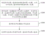
Referring to fig. 7, the present embodiment further provides a manufacturing method for manufacturing a heat generating component, where the heat generating component includes a first substrate 10 and a second substrate 20, the first substrate 10 is formed with a middle channel 10a; the second base body 20 is formed with a housing passage 20a, the first base body 10 is housed in the housing passage 20a, a space 20a 'is provided between an outer peripheral surface of the first base body 10 and a wall surface of the housing passage 20a, the space 20a' is empty or filled with a porous member, one of the wall surface of the intermediate passage 10a and the outer peripheral surface of the second base body 20 is a heat generation surface, and the other of the wall surface of the intermediate passage 10a and the outer peripheral surface of the second base body 20 is a liquid intake surface, the manufacturing method includes:
s100, manufacturing a first reverse mold nested with the structure of the first substrate and a second reverse mold nested with the structure of the second substrate.
Referring to fig. 8 to 11, the structure of the first inverse mold 1 is nested with the structure of the first substrate 10, that is, all the faces of the first inverse mold 1 can overlap with all the faces of the first substrate 10. The structure of the second reverse mold is nested with the structure of the second substrate 20, that is, all faces of the second reverse mold can overlap with all faces of the second substrate 20.
S200, sleeving the first reverse mold in the second reverse mold, and placing a breaking mold between the first reverse mold and the second reverse mold, wherein the first reverse mold, the second reverse mold and the breaking mold are all placed in an outer mold to jointly define a mold cavity.
The contour of the outer die can be adapted to the contour of the second base body 20, the surface of the outer die facing the second counter die and the second counter die together forming a die cavity.
Illustratively, the outline shape of the second reverse mold is in a rotating body shape, the outer mold is also in the same rotating body shape, and the number of the surfaces of the second reverse mold is equal to that of the surfaces of the outer mold. In addition, the shape of the surface of the second reverse mold and the shape of the surface of the outer mold are in one-to-one correspondence and are the same, but the volume of the second reverse mold and the volume of the outer mold may be different.
Illustratively, the partition mold may also be a disposable sacrificial mold. In this manner, a spacing space is facilitated to be formed between the first substrate and the second substrate.
In some embodiments, the cut-off die may be a compact. Thus, after the partition die is removed, an empty partition space is formed.
In some embodiments, the cut-off die may also be a porous structure. Thus, the porous member is formed after the slurry is filled and the partition mold is removed.
The material of the partition die is not limited, and the partition die can be made of high polymer material.
S300, filling the die cavity with slurry to form a green blank.
The slurry is a constituent material of the first substrate 10 and the second substrate 20, for example, the slurry may be a ceramic material. The slurry has a temperature such that the slurry is in a flowing liquid state. The slurry is in a solid state when the temperature of the slurry drops below the freezing point. The slurry solidifies to a solid state to form a green body.
S400, processing the green body to form the first matrix and the second matrix.
The first substrate 10 and the second substrate 20 are formed after the secondary treatment according to the condition of the green body.
The manufacturing method provided by the application can be used for manufacturing the heating component in any embodiment of the application.
In the related art, the overflowing hole of the first substrate and the communicating hole of the second substrate need to be formed by adopting laser induction, corrosion hole forming and the like, and the production mode has high production equipment cost and higher process requirement.
According to the manufacturing method, the first reverse mold 1 nested with the structure of the first base body 10 and the second reverse mold nested with the structure of the second base body 20 are manufactured firstly, and then the first base body 10 and the second base body 20 are formed through the first reverse mold 1 and the second reverse mold in a grouting mode.
For example, in some embodiments, a first soft template and a second soft template may be manufactured separately, wherein the first soft template comprises a first plate and the second soft template comprises a second plate;
the first flat sheet is wound into a hollow annular structure to form the first countermold, and the second flat sheet is wound into a hollow annular structure to form the second countermold.
In some embodiments, referring to fig. 8 to 11, the first base body 10 is formed with a plurality of overflow holes 10b, the second base body 20 is formed with a plurality of communication holes 20b, the overflow holes 10b communicate the intermediate channel 10a and the spacing space 20a ', the communication holes 20b communicate the spacing space 20a' with the outer circumferential surface of the second base body 20, the first reverse mold 1 has a first pillar 12 nested with the overflow holes 10b, and the second reverse mold has a second pillar nested with the communication holes 20b.
Referring to fig. 8 to 11, the structure of the first reverse mold 1 is nested with the structure of the first substrate 10, that is, all the surfaces of the first reverse mold 1 can overlap all the surfaces of the first substrate 10, and the first pillars 12 of the first reverse mold 1 can be embedded into the overflow holes 10b of the first substrate 10. The structure of the second reverse mold 2 is nested with the structure of the second base 20, that is, all the faces of the second reverse mold can overlap with all the faces of the second base 20, and the second posts of the second reverse mold can be embedded in the communication holes 20b of the second base 20.
The length of the first column 12 can be determined according to the length of the overflowing hole 10b, and in some embodiments, the length of the first column 12 is not less than the length of the overflowing hole 10 b. In this way, it is ensured that the final formed overflowing hole 10b is a through hole.
The length of the second pillar may be determined according to the length of the communication hole 20b, and in some embodiments, the length of the second pillar is not less than the length of the communication hole 20b. Thus, the communication hole 20b finally formed is ensured to be a through hole.
Taking the slurry as the ceramic as an example, S300, filling the mold cavity with the slurry to form a green body may include:
s310, curing the slurry in the die cavity in a light curing mode to form the green blank.
This allows the ceramic slurry in the mold cavity to be quickly cured to save time for curing. The ceramic slurry may be cured, for example, by ultraviolet light.
In one embodiment, the step S400 of processing the green body to form the first substrate and the second substrate comprises:
s410, sintering the green body to form the first base body and the second base body.
And carrying out high-temperature binder removal and sintering on the green body to form a first substrate 10 and a second substrate 20.
It is understood that the through-hole processing may be performed on the green body in the case where the overflowing holes 10b and/or the communicating holes 20b of the green body are clogged with the remaining slurry.
In one embodiment, the manufacturing method includes:
s500, manufacturing a first master die with the same structure as the first matrix and a second master die with the same structure as the second matrix, and manufacturing the first reverse die according to the first master die and the second reverse die according to the second master die.
Referring to fig. 8, in the present embodiment, a large number of first reverse molds 1 and second reverse molds can be mass-produced by one or a small number of first mother molds 2 and second mother molds.
The first mother die 2 and the second mother die can be produced in any manner, but for example, the first mother die 2 and the second mother die can be produced by drilling or the like. The first female die 2 and the second female die are small in demand, the machining and forming modes can be diversified, and the production cost can be effectively controlled.
It will be appreciated that the first reverse mold 1 nests with the first master mold 2. The second reverse mold is nested with the second master mold.
In one embodiment, after processing the green body to form the first substrate and the second substrate, the method of manufacturing comprises:
and coating or brushing a film on the heating surface to form a heating film.
For example, in one embodiment, the heat generating film 30 can be deposited on the heat generating surface by physical vapor deposition or chemical vapor deposition. Thus, the heat generating film 30 is formed on the heat generating surface by plating. In this way, on one hand, the heating film 30 can be tightly combined with the heating surface to reduce the assembling steps, and on the other hand, the thickness of the heating film 30 can be within the range of micron or nanometer thickness, so that the requirement of overall miniaturization of the heating component can be met, and the material of the heating film 30 can be saved.
Illustratively, in one embodiment, the film is brushed on the heat generating surface to form the heat generating film 30. Illustratively, the heating film 30 is prepared by doctor-blading a conductive paste to prepare a thick film.
In one embodiment, the first reverse mold 1 is made of a soft material. Thus, on the one hand, the first countermold 1 is low in cost; on the other hand, the first reverse mold 1 is easily separated from the first mother mold 2, and the first reverse mold 1 is also easily separated from the green body, and neither the first mother mold 2 nor the green body is easily damaged.
Soft materials include, but are not limited to, soft polymer materials. For example, soft silicone or soft resin, etc.
In one embodiment, the first reverse mold 1 is a disposable sacrificial mold. The sacrificial mold used once means a mold for completing the production of a single first substrate 10, i.e., being discarded. So, when separating first countermould 1 and embryo, can destroy first countermould 1, like this, first countermould 1 can with embryo quick separation, the operation of being convenient for.
In one embodiment, the second reverse mold is made of a soft material. Thus, on the one hand, the cost of the second reverse mold is lower; on the other hand, the second reverse mold is easy to separate from the second mother mold, and the second reverse mold is also easy to separate from the green blank, so that the second mother mold and the green blank are not easily damaged.
Soft materials include, but are not limited to, soft polymer materials. For example, soft silicone or soft resin, etc.
In one embodiment, the second reverse mold is a sacrificial disposable mold. The sacrificial mold once refers to a mold that completes the production of a single first substrate 10, i.e., is discarded. So, when separating second countermould and embryo, can destroy the second countermould, like this, the second countermould can with embryo quickly separating, the operation of being convenient for.
In one embodiment, fabricating a first reverse mold nested with the structure of the first substrate and a second reverse mold nested with the structure of the second substrate comprises:
and S110, respectively manufacturing a first soft template and a second soft template, wherein the first soft template comprises a first flat plate and a plurality of first stand columns positioned on the first flat plate, and the second soft template comprises a second flat plate and a plurality of second stand columns positioned on the second flat plate.
The first soft template is a structure capable of deforming under a small acting force. The first soft template is of an integrated structure, so that the assembly steps can be reduced, and the manufacturing process is simplified.
The second soft template is a structure capable of deforming under a small acting force. The second soft template is of an integrally formed structure, so that the assembly steps can be reduced, and the manufacturing process is simplified.
For example, a hard material such as a metal material or a steel material can be used for each of the first mother die 2 and the second mother die so that the first mother die 2 and the second mother die can be used repeatedly. The first flat plate 11 is easy to be separated from the first female die 2, and the second flat plate is easy to be separated from the second female die, so that the manufacturing difficulty of the first reverse die 1 and the second reverse die is reduced.
And S120, winding the first flat plate into a hollow circular ring structure to form the first reverse mold, and winding the second flat plate into a hollow circular ring structure to form the second reverse mold, wherein the first upright is towards the outer side, and the second upright is towards the inner side.
Here, the first plate 11 is wound into a hollow circular ring structure by using the deformation capability of the first flexible template to form a three-dimensional shape of the first reverse mold 1. The second plate is coiled into a hollow circular ring structure by utilizing the deformation capability of the second soft template to form a second reverse mould three-dimensional shape.
In one embodiment, the first flexible template is formed by integral injection molding. For example, a hot pressing process may be used to press a melt formed by a high-temperature molten polymer material into the first female mold 2, and after cooling, the first female mold 2 is removed to obtain the first soft template.
In one embodiment, the second flexible template is formed by integral injection molding. For example, a hot pressing process may be used to press a melt formed by a high-temperature molten polymer material into the second master mold, and after cooling, the second master mold is removed to obtain the second soft template.
In an exemplary embodiment, the first substrate 10 and the first reverse mold 1 are cylindrical in outline shape, the first soft template includes a first flat plate 11 having a rectangular shape, two sides of the first flat plate 11 are connected by winding to form a three-dimensional cylindrical first reverse mold 1, and two axial sides of the cylindrical first reverse mold 1 are open. It is understood that, in the case where the outline shapes of the second substrate 20 and the second reverse mold are both cylindrical, the second reverse mold is formed in the same manner as described above, and thus, the description thereof is omitted.
In an exemplary embodiment, the first reverse mold 1 has a truncated cone shape in outline, the first soft template includes a first plate 11 in an isosceles trapezoid shape, the two waists of the first plate 11 are connected by winding to form the first reverse mold 1 of the three-dimensional truncated cone, and the two axial sides of the first reverse mold 1 of the truncated cone are open. It is understood that, in the case that the contour shapes of the second substrate 20 and the second reverse mold are both truncated cones, the second reverse mold is formed in the same manner as described above, and will not be described again.
The above description is only for the specific embodiments of the present application, but the scope of the present application is not limited thereto, and any person skilled in the art can easily conceive of changes or substitutions after the technical scope of the present application, and shall be covered by the scope of the present application. Therefore, the protection scope of the present application shall be subject to the protection scope of the claims.