CN115719380A - Visual robot fusion method - Google Patents
Visual robot fusion method Download PDFInfo
- Publication number
- CN115719380A CN115719380A CN202211483736.XA CN202211483736A CN115719380A CN 115719380 A CN115719380 A CN 115719380A CN 202211483736 A CN202211483736 A CN 202211483736A CN 115719380 A CN115719380 A CN 115719380A
- Authority
- CN
- China
- Prior art keywords
- coordinate system
- robot
- feature
- physical
- pattern
- Prior art date
- Legal status (The legal status is an assumption and is not a legal conclusion. Google has not performed a legal analysis and makes no representation as to the accuracy of the status listed.)
- Granted
Links
Images


Landscapes
- Manipulator (AREA)
Abstract
本发明公开了一种视觉机器人融合方法,旨在克服现有技术中定位不准确的问题,它包括工件坐标系和工具坐标系建立流程、N点标定流程、模板制作流程、特征图像处理流程、姿态自适应流程和高度自动调节流程。

The invention discloses a visual robot fusion method, aiming at overcoming the problem of inaccurate positioning in the prior art, which includes the establishment process of workpiece coordinate system and tool coordinate system, N point calibration process, template production process, feature image processing process, Attitude adaptive process and height automatic adjustment process.
Description
技术领域technical field
本发明属于机器视觉技术,特指一种视觉机器人融合方法。The invention belongs to machine vision technology, in particular to a visual robot fusion method.
背景技术Background technique
机器人定位精度是衡量其工作性能的一个重要指标,目前,国内外厂家生成出来的视觉机器人由于制造、安装等因素,大多定位精度不高,无法满足高精度加工的需要,因此对引起机器人定位误差的各种因素进行分析,最大可能地提高机器人绝对定位精度已成为机器视觉技术的研究核心内容。Robot positioning accuracy is an important index to measure its working performance. At present, due to factors such as manufacturing and installation, most of the visual robots produced by domestic and foreign manufacturers have low positioning accuracy and cannot meet the needs of high-precision processing. It has become the core content of machine vision technology to analyze various factors and improve the absolute positioning accuracy of robots as much as possible.
目前,国内外常用的机器人标定方法通常借助外界先进的测量设备完成,但是这就导致了成本高、测量过程复杂以及需要专业人士操作的问题,同时在涉及坐标系转换过程中,容易引入坐标系转换误差,还导致了测量误差较大的问题。At present, the commonly used robot calibration methods at home and abroad are usually completed with the help of external advanced measuring equipment, but this leads to problems such as high cost, complicated measurement process, and the need for professional operation. At the same time, it is easy to introduce coordinate system The conversion error also leads to the problem of large measurement error.
针对上述现状,本发明提出了一种视觉机器人融合方法,用以解决定位标定的问题。In view of the above current situation, the present invention proposes a visual robot fusion method to solve the problem of positioning and calibration.
发明内容Contents of the invention
为克服现有技术的不足及存在的问题,本发明提供一种视觉机器人系统及其融合方法。In order to overcome the deficiencies and existing problems of the prior art, the present invention provides a visual robot system and a fusion method thereof.
为实现上述目的,本发明采用如下技术方案:To achieve the above object, the present invention adopts the following technical solutions:
一方面,本发明提供了一种视觉机器人系统,用于执行工件坐标系和工具坐标系建立流程、执行模板制作流程、模板制作流程、特征点位置逼近流程、特征图像处理流程、姿态自适应流程和高度自动调节流程,系统包括:On the one hand, the present invention provides a visual robot system, which is used to execute the establishment process of the workpiece coordinate system and the tool coordinate system, execute the template production process, the template production process, the feature point position approximation process, the feature image processing process, and the attitude self-adaptation process And height automatic adjustment process, the system includes:
机器人,其包括执行机构;a robot including an actuator;
二维相机,其设置在执行机构的末端;a two-dimensional camera, which is arranged at the end of the actuator;
工作台,其上用于定位工件;a workbench on which the workpiece is positioned;
特征图案,其包括特征点和特征线段。A feature pattern, which includes feature points and feature line segments.
作为优选,所述工件坐标系和工具坐标系建立流程包括视觉机器人系统建立工件坐标系和工具坐标系流程,其中,工具坐标系包括TCP位置。Preferably, the process of establishing the workpiece coordinate system and the tool coordinate system includes the process of establishing the workpiece coordinate system and the tool coordinate system by the vision robot system, wherein the tool coordinate system includes the TCP position.
作为优选,所述N点标定流程包括视觉机器人系统建立图像坐标系和机器人物理坐标系之间的转换矩阵,其中,N为正整数。Preferably, the N-point calibration process includes the visual robot system establishing a transformation matrix between the image coordinate system and the robot physical coordinate system, wherein N is a positive integer.
作为优选,所述模板制作流程包括视觉机器人系统调整二维相机对特征图案的拍摄位姿,触发二维相机拍照并获取图像,对图像进行处理得到特征图案的像素轮廓,将特征图案的像素轮廓作为定位模板,对定位模板进行计算得到定位模板物理几何参数,其中,特征图案包括特征点和特征线段。Preferably, the template production process includes the visual robot system adjusting the shooting pose of the two-dimensional camera to the characteristic pattern, triggering the two-dimensional camera to take pictures and acquiring the image, processing the image to obtain the pixel outline of the characteristic pattern, and converting the pixel outline of the characteristic pattern As the positioning template, the positioning template is calculated to obtain the physical geometry parameters of the positioning template, wherein the feature pattern includes feature points and feature line segments.
作为优选,所述特征点位置逼近流程包括视觉机器人系统将特征图案设置在工件上,触发相机拍照并获取图像,对图像执行特征图像处理流程得到特征轮廓物理几何参数,控制相机在机器人物理坐标系X轴和Y轴上平移使得特征轮廓物理几何参数逼近定位模板物理几何参数。Preferably, the process of approaching the position of the feature point includes setting the feature pattern on the workpiece by the visual robot system, triggering the camera to take pictures and acquiring the image, executing the feature image processing process on the image to obtain the physical geometric parameters of the feature contour, and controlling the camera to be in the robot physical coordinate system The translation on the X-axis and the Y-axis makes the physical geometric parameters of the feature contour approach the physical geometric parameters of the positioning template.
作为优选,所述特征图像处理流程包括视觉机器人系统对图像进行处理得到特征图案的轮廓,判断特征图案的轮廓和定位模板是否相匹配,若是则将特征图案的轮廓作为特征轮廓并根据特征轮廓计算得到特征轮廓物理几何参数,若否则重新调整二维相机对特征图案的拍摄位姿、触发二维相机拍照并获取图像,其中,特征轮廓为特征图案的像素轮廓。Preferably, the characteristic image processing flow includes processing the image by the visual robot system to obtain the contour of the characteristic pattern, judging whether the contour of the characteristic pattern matches the positioning template, and if so, using the contour of the characteristic pattern as the characteristic contour and calculating according to the characteristic pattern Obtain the physical geometry parameters of the feature profile, if not, readjust the shooting pose of the 2D camera to the feature pattern, trigger the 2D camera to take pictures and obtain an image, wherein the feature profile is the pixel profile of the feature pattern.
作为优选,所述姿态自适应流程包括视觉机器人系统分别控制二维相机绕机器人物理坐标系X轴、Y轴和Z轴旋转使得特征轮廓物理几何参数逼近定位模板物理几何参数。Preferably, the posture adaptation process includes the visual robot system controlling the rotation of the two-dimensional camera around the X-axis, Y-axis and Z-axis of the robot's physical coordinate system so that the physical geometric parameters of the feature contour approach the physical geometric parameters of the positioning template.
作为优选,所述高度自动调节流程包括视觉机器人系统控制二维相机在机器人物理坐标系Z轴上平移使得特征轮廓物理几何参数逼近定位模板物理几何参数。Preferably, the height automatic adjustment process includes the visual robot system controlling the two-dimensional camera to translate on the Z-axis of the robot's physical coordinate system so that the physical geometric parameters of the feature contour approach the physical geometric parameters of the positioning template.
另一方面,本发明还提供了一种视觉机器人融合方法,采用上述的一种视觉机器人系统执行,包括如下步骤:On the other hand, the present invention also provides a visual robot fusion method, which is implemented by using the above-mentioned visual robot system, including the following steps:
工件坐标系和工具坐标系建立流程:建立工件坐标系和工具坐标系流程,其中,工具坐标系包括TCP位置;Workpiece coordinate system and tool coordinate system establishment process: establish the workpiece coordinate system and tool coordinate system process, wherein the tool coordinate system includes the TCP position;
N点标定流程:建立图像坐标系和机器人物理坐标系之间的转换矩阵,其中,N为正整数;N-point calibration process: establish a conversion matrix between the image coordinate system and the robot physical coordinate system, where N is a positive integer;
模板制作流程:调整二维相机对特征图案的拍摄位姿,触发二维相机拍照并获取图像,对图像进行处理得到特征图案的像素轮廓,将特征图案的像素轮廓作为定位模板,对定位模板进行计算得到定位模板物理几何参数,其中,特征图案包括特征点和特征线段;Template production process: adjust the shooting pose of the two-dimensional camera for the feature pattern, trigger the two-dimensional camera to take pictures and obtain the image, process the image to obtain the pixel outline of the feature pattern, use the pixel outline of the feature pattern as a positioning template, and carry out the positioning template Calculate and obtain the physical geometry parameters of the positioning template, wherein the feature pattern includes feature points and feature line segments;
特征点位置逼近流程:将特征图案设置在工件上,触发相机拍照并获取图像,对图像执行特征图像处理流程得到特征轮廓物理几何参数,控制相机在机器人物理坐标系X轴和Y轴上平移使得特征轮廓物理几何参数逼近定位模板物理几何参数;Feature point position approximation process: set the feature pattern on the workpiece, trigger the camera to take pictures and acquire the image, perform feature image processing on the image to obtain the physical geometry parameters of the feature outline, and control the camera to translate on the X-axis and Y-axis of the robot's physical coordinate system so that The physical geometric parameters of the feature contour approximate the physical geometric parameters of the positioning template;
特征图像处理流程:对图像进行处理得到特征图案的轮廓,判断特征图案的轮廓和定位模板是否相匹配,若是则将特征图案的轮廓作为特征轮廓并根据特征轮廓计算得到特征轮廓物理几何参数,若否则重新调整二维相机对特征图案的拍摄位姿、触发二维相机拍照并获取图像,其中,特征轮廓为特征图案的像素轮廓;Feature image processing flow: process the image to obtain the outline of the feature pattern, judge whether the outline of the feature pattern matches the positioning template, if so, use the outline of the feature pattern as the feature outline and calculate the physical geometry parameters of the feature outline according to the feature outline, if Otherwise, readjust the shooting pose of the two-dimensional camera to the characteristic pattern, trigger the two-dimensional camera to take pictures and obtain the image, wherein the characteristic contour is the pixel contour of the characteristic pattern;
姿态自适应流程:分别控制二维相机绕机器人物理坐标系X轴、Y轴和Z轴旋转使得特征轮廓物理几何参数逼近定位模板物理几何参数;Attitude adaptive process: respectively control the two-dimensional camera to rotate around the X-axis, Y-axis and Z-axis of the robot's physical coordinate system so that the physical geometric parameters of the feature contour approach the physical geometric parameters of the positioning template;
高度自动调节流程:控制二维相机在机器人物理坐标系Z轴上平移使得特征轮廓物理几何参数逼近定位模板物理几何参数。Height automatic adjustment process: Control the translation of the two-dimensional camera on the Z-axis of the robot's physical coordinate system so that the physical geometric parameters of the feature contour approach the physical geometric parameters of the positioning template.
作为优选,所述工件坐标系和工具坐标系建立流程,具体包括如下步骤:Preferably, the process for establishing the workpiece coordinate system and the tool coordinate system specifically includes the following steps:
步骤111:建立工具坐标系并确定TCP位置,将TCP位置设置在视觉中心点上,其中,视觉中心指的是二维相机镜头下端面中心;Step 111: establish the tool coordinate system and determine the TCP position, and set the TCP position on the visual center point, wherein the visual center refers to the center of the lower end surface of the two-dimensional camera lens;
步骤112:通过工件坐标系确定机器人的工作面,工件坐标系的XY平面建立在加工面上,其中,加工面为特征图案上的切面,加工面和特征图案的公共点为特征点。Step 112: Determine the working surface of the robot through the workpiece coordinate system. The XY plane of the workpiece coordinate system is established on the processing surface, wherein the processing surface is a tangent surface on the feature pattern, and the common point of the processing surface and the feature pattern is a feature point.
作为优选,所述N点标定流程,具体包括如下流程:As preferably, the N-point calibration process specifically includes the following process:
步骤121:将TCP位置设置在视觉中心上;Step 121: set the TCP position on the visual center;
步骤122:控制二维相机正对于加工面,控制物距达到设定值;Step 122: Control the two-dimensional camera to face the processing surface, and control the object distance to reach the set value;
步骤123:在加工面上设置N个标定点,N个标定点的物理坐标分别为(X1,Y1,Z1)、(X2,Y2,Z2)…(XN,YN,ZN),控制TCP移动至N个标定点上并获取标定图像,根据标定图像确定TCP在N标定点上的像素坐标,TCP在N标定点上的像素坐标分别为(x1,y1)、(x2,y2)…(xN,yN);Step 123: Set N calibration points on the processing plane, the physical coordinates of the N calibration points are (X 1 , Y 1 , Z 1 ), (X 2 , Y 2 , Z 2 )...(X N , Y N , Z N ), control TCP to move to N calibration points and obtain calibration images, determine the pixel coordinates of TCP on N calibration points according to the calibration images, and the pixel coordinates of TCP on N calibration points are (x 1 , y 1 ), (x 2 ,y 2 )…(x N ,y N );
步骤124:根据N个标定点的物理坐标和TCP在N标定点上的像素坐标代入如下公式并根据最小二乘法计算得到转换矩阵:Step 124: Substituting the following formula according to the physical coordinates of the N calibration points and the pixel coordinates of the TCP on the N calibration points and calculating the conversion matrix according to the least square method:
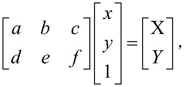
式中,转换矩阵为
作为优选,所述模板制作流程,具体包括如下步骤:Preferably, the template making process specifically includes the following steps:
步骤131:调整二维相机对特征图案的拍摄位姿,触发二维相机拍照并获取图像,其中,特征图案包括特征点和特征线段;步骤132:获取特征图案的像素轮廓,将特征图案的像素轮廓作为定位模板;步骤133:根据定位模板计算得到定位模板像素几何参数,通过转换矩阵将定位模板像素几何参数转换为定位模板物理几何参数,其中,定位模板几何参数包括特征点的位置参数和特征线段的尺寸参数。Step 131: Adjust the shooting pose of the two-dimensional camera to the feature pattern, trigger the two-dimensional camera to take pictures and acquire images, wherein the feature pattern includes feature points and feature line segments; Step 132: Get the pixel outline of the feature pattern, and convert the pixel profile of the feature pattern The outline is used as a positioning template; Step 133: Calculate the pixel geometric parameters of the positioning template according to the positioning template, and convert the pixel geometric parameters of the positioning template into the physical geometric parameters of the positioning template through the transformation matrix, wherein the positioning template geometric parameters include the position parameters of feature points and feature points The size parameter of the line segment.
作为优选,所述特征点位置逼近流程,具体包括如下步骤:Preferably, the feature point position approximation process specifically includes the following steps:
步骤211:将特征图案设置在工件上,将工件定位在工作台上;Step 211: setting the feature pattern on the workpiece, and positioning the workpiece on the workbench;
步骤212:触发二维相机拍照并获取图像;Step 212: trigger the two-dimensional camera to take pictures and acquire images;
步骤213:对图像执行特征图像处理流程得到特征轮廓物理几何参数;Step 213: Execute the characteristic image processing flow on the image to obtain the physical geometry parameters of the characteristic contour;
步骤214:根据定位模板物理几何参数和特征轮廓物理几何参数计算得到偏移量,其中,偏移量包括ΔTX和ΔTY,ΔTX为在特征轮廓相对定位模板在机器人物理坐标系X轴上的偏移量,ΔTY为特征轮廓相对定位模板在机器人物理坐标系Y轴上的偏移量;Step 214: Calculate the offset according to the physical geometric parameters of the positioning template and the physical geometric parameters of the feature contour, wherein the offset includes ΔT X and ΔT Y , and ΔT X is the relative positioning template on the feature contour on the X axis of the robot physical coordinate system ΔT Y is the offset of the feature contour relative to the positioning template on the Y axis of the robot's physical coordinate system;
步骤215:判断ΔTX是否小于阈值ΔXi,若ΔTX不小于阈值ΔXi则判断ΔTX是否超过阈值


步骤216:若ΔTX小于阈值ΔXi时则判断ΔTY是否小于阈值ΔYi,若ΔTY不小于阈值ΔYi则判断ΔTY是否超过阈值


作为优选,所述特征图像处理流程,具体包括如下步骤:Preferably, the feature image processing flow specifically includes the following steps:
S11:视觉机器人系统根据Canny算法,提取图像中图案的边缘点;S11: The visual robot system extracts the edge points of the pattern in the image according to the Canny algorithm;
S12:视觉机器人系统根据提取到的图案的边缘点生成图案轮廓,其中,图案轮廓由若干边缘点构成;S12: The visual robot system generates a pattern outline according to the extracted edge points of the pattern, wherein the pattern outline is composed of several edge points;
S13:视觉机器人系统根据图案轮廓计算得到图案轮廓的边缘点数量和长宽比,判断图案轮廓的边缘点数量是否位于安全数量范围内以及图案轮廓的长宽比是否位于安全长宽比范围内,若是则保留相应的图案轮廓,若否则剔除相应的图案轮廓;S13: The visual robot system calculates the number of edge points and the aspect ratio of the pattern outline according to the pattern outline, and judges whether the number of edge points of the pattern outline is within the safe range and whether the aspect ratio of the pattern outline is within the safe aspect ratio range, If so, keep the corresponding pattern outline, otherwise remove the corresponding pattern outline;
S14:视觉机器人系统判断保留下来的图案轮廓的一个边缘点和相邻的边缘点之间的差值是否位于梯度变化阈值时,若是则判定该边缘点为轮廓交点,判断图案轮廓的轮廓交点是否位于安全交点数范围内,若是则根据该图案轮廓的轮廓交点重新构建得到特征图案的轮廓;S14: When the visual robot system judges whether the difference between an edge point of the retained pattern outline and an adjacent edge point is at the gradient change threshold, if so, it is determined that the edge point is the intersection point of the outline, and whether the intersection point of the outline of the pattern outline is judged to be Located within the range of safe intersection points, if so, reconstruct the outline of the feature pattern according to the outline intersection of the pattern outline;
S15:视觉机器人系统根据特征图案的轮廓计算得到特征图案像素几何参数,根据转换矩阵将特征图案像素几何参数转换为特征图案物理几何参数,判断特征图案像素几何参数和定位模板物理几何参数是否构成相似关系,若是则判定特征图案和定位模板匹配成功并将特征图案的轮廓作为特征轮廓,若否则判定特征图案和定位模板匹配不成功并重新调整二维相机对特征图案的拍摄位姿并获取图像。S15: The visual robot system calculates the pixel geometric parameters of the feature pattern according to the outline of the feature pattern, converts the pixel geometric parameters of the feature pattern into the physical geometry parameters of the feature pattern according to the transformation matrix, and judges whether the pixel geometry parameters of the feature pattern and the physical geometry parameters of the positioning template are similar relationship, if it is determined that the matching between the feature pattern and the positioning template is successful and the contour of the feature pattern is used as the feature contour, otherwise it is judged that the matching between the feature pattern and the positioning template is unsuccessful and the two-dimensional camera is readjusted to the shooting pose of the feature pattern and the image is obtained.
作为优选,所述姿态自适应流程,具体包括如下步骤:As preferably, the posture adaptation process specifically includes the following steps:
步骤221:触发二维相机拍照并获取图像;Step 221: trigger the two-dimensional camera to take pictures and acquire images;
步骤222:对图像执行特征图像处理流程得到特征轮廓物理几何参数;Step 222: Execute the characteristic image processing flow on the image to obtain the physical geometry parameters of the characteristic contour;
步骤223:根据特征轮廓物理几何参数和定位模板物理几何参数计算得到偏移量,偏移量包括θZ1、θX1和θY1,θZ1为特征轮廓相对定位模板在机器人物理坐标系Z轴上的偏移角度,θX1为特征轮廓相对定位模板在机器人物理坐标系X轴上的偏移角度,θY1为特征轮廓相对定位模板在机器人物理坐标系Y轴上的偏移角度;Step 223: Calculate the offset according to the physical geometric parameters of the feature contour and the physical geometric parameters of the positioning template. The offset includes θ Z1 , θ X1 and θ Y1 , and θ Z1 is the relative positioning template of the feature profile on the Z-axis of the robot's physical coordinate system The offset angle of , θ X1 is the offset angle of the feature profile relative to the positioning template on the X axis of the robot physical coordinate system, and θ Y1 is the offset angle of the feature profile relative to the positioning template on the Y axis of the robot physical coordinate system;
步骤224:判断θZ1是否小于阈值θZ,若否则控制二维相机绕机器人物理坐标系Z轴旋转直至小于阈值θZ;Step 224: Determine whether θ Z1 is smaller than the threshold θ Z , if not, control the two-dimensional camera to rotate around the Z-axis of the robot's physical coordinate system until it is smaller than the threshold θ Z ;
步骤225:若θZ1小于阈值θZ则判断θX1是否小于阈值θX,若θX1不小于阈值θX则判断θX1是否大于阈值


步骤226:若θX1小于阈值θX则执行特征点逼近流程,再判断θY1是否小于阈值θY,若θY1不小于阈值θY则判断θY1是否大于阈值


步骤227:若θY1小于阈值θY时则执行特征点位置逼近流程,记录机器人的当前姿态信息。Step 227: If θ Y1 is less than the threshold θ Y , execute the feature point position approximation process, and record the current posture information of the robot.
作为优选,所述高度自动调节流程,包括如下步骤:As preferably, the automatic height adjustment procedure includes the steps of:
步骤241:触发二维相机拍照并获取图像;Step 241: trigger the two-dimensional camera to take pictures and acquire images;
步骤242:对图像执行特征图像处理流程得到特征轮廓物理几何参数;Step 242: Execute the characteristic image processing flow on the image to obtain the physical geometry parameters of the characteristic contour;
步骤243:根据特征轮廓物理几何参数和定位模板物理几何参数计算得到偏移量,偏移量包括ΔH,ΔH为特征轮廓相对定位模板的高度偏移量;Step 243: Calculate the offset according to the physical geometric parameters of the feature profile and the physical geometric parameters of the positioning template, the offset includes ΔH, and ΔH is the height offset of the feature profile relative to the positioning template;
步骤244:判断ΔH是否小于阈值ΔH1,若ΔH小于阈值ΔH1则判断ΔH是否大于阈值ΔH2,若ΔH大于阈值ΔH2则控制二维相机在机器人物理坐标系Z轴上平移直至ΔH不大于阈值ΔH2,若ΔH不大于阈值ΔH2则控制二维相机在机器人物理坐标系Z轴上迭代平移


本发明相比现有技术突出且有益的技术效果是:Compared with the prior art, the present invention has outstanding and beneficial technical effects as follows:
(1)在本发明中,通过二维相机拍摄到的图像进行处理,实现二维相机位置调节、工件位置定位和机器人姿态调整,从而实现了执行机构在特征位置上对工件进行定位加工的效果,适合用于具有复杂表面的工件定位加工,因此本发明具有定位效率高和定位准确的优点。(1) In the present invention, the image captured by the two-dimensional camera is processed to realize the position adjustment of the two-dimensional camera, the position of the workpiece and the adjustment of the robot posture, thereby realizing the effect of positioning and processing the workpiece by the actuator at the characteristic position , suitable for positioning processing of workpieces with complex surfaces, so the invention has the advantages of high positioning efficiency and accurate positioning.
(2)在本发明中,在定位过程中,采用逐次逼近和粗调细调结合的方式用于实现像素轮廓逐步逼近定位模板,一方面提高了二维相机位置调节效率,另一方面降低了二维相机定位误差。(2) In the present invention, in the positioning process, the combination of successive approximation and coarse adjustment and fine adjustment is used to realize the gradual approach of the pixel contour to the positioning template. On the one hand, the efficiency of two-dimensional camera position adjustment is improved, and on the other hand, the 2D camera positioning error.
(3)在本发明中,机器人和执行机构的姿态被严格定位,避免姿态异常干扰后续机器人对工件加工,保证了工件的加工精度和质量。(3) In the present invention, the postures of the robot and the actuator are strictly positioned to avoid abnormal postures from interfering with the subsequent processing of the workpiece by the robot, thereby ensuring the processing accuracy and quality of the workpiece.
附图说明Description of drawings
图1是本发明的视觉机器人系统的结构示意图;Fig. 1 is the structural representation of vision robot system of the present invention;
图2是本发明的特征图案的结构示意图;Fig. 2 is a structural schematic diagram of a characteristic pattern of the present invention;
图3是本发明的视觉机器人融合方法的总流程示意图;Fig. 3 is a schematic diagram of the overall flow of the visual robot fusion method of the present invention;
图4是本发明的视觉机器人融合方法中的9个标定点在工件上的分布示意图;Fig. 4 is a schematic diagram of the distribution of 9 calibration points on the workpiece in the visual robot fusion method of the present invention;
图5是本发明的视觉机器人融合方法中模板制作流程的示意图;Fig. 5 is a schematic diagram of the template making process in the visual robot fusion method of the present invention;
图6是本发明的视觉机器人融合方法中特征点位置逼近流程的示意图;6 is a schematic diagram of a feature point position approximation process in the visual robot fusion method of the present invention;
图7是本发明的在X方向上粗调和细调流程中特征点位置示意图;Fig. 7 is a schematic diagram of the positions of feature points in the rough adjustment and fine adjustment processes in the X direction of the present invention;
图8是本发明的视觉机器人融合方法中姿态自适应流程的示意图;Fig. 8 is a schematic diagram of the posture adaptive process in the visual robot fusion method of the present invention;
图9是本发明的视觉机器人融合方法中高度自动调节流程示意图;Fig. 9 is a schematic diagram of the height automatic adjustment process in the visual robot fusion method of the present invention;
图中:1-机器人、2-二维相机、3-工作台、4-工件、5-特征图案、6-刀具、11-执行机构。In the figure: 1-robot, 2-two-dimensional camera, 3-table, 4-workpiece, 5-characteristic pattern, 6-tool, 11-executing mechanism.
具体实施方式Detailed ways
为了便于本领域技术人员的理解,下面结合附图和具体实施例对本发明作进一步描述。In order to facilitate the understanding of those skilled in the art, the present invention will be further described below in conjunction with the drawings and specific embodiments.
如图1所示,一种视觉机器人系统,包括机器人、二维相机、工作台、工件、特征图案、光电开关和触摸屏。As shown in Figure 1, a visual robot system includes a robot, a two-dimensional camera, a workbench, a workpiece, a feature pattern, a photoelectric switch, and a touch screen.
机器人包括执行机构,执行机构用于将机器人的控制信号转换为相应姿态动作的机械臂,是机器人完成工作任务的主要实体,本实施例中,采用的执行机构属于现有技术,也是采用包括一些系列的连杆、机械关节、位姿传感器等构成的机械臂。执行机构的底部安装有底座,执行机构的末端安装有刀具,刀具用以在工作时对工件进行加工的主要器具,在本实施例中,刀具为切削工具。The robot includes an actuator. The actuator is used to convert the control signal of the robot into a mechanical arm corresponding to the posture action. It is the main entity for the robot to complete the task. A series of connecting rods, mechanical joints, pose sensors, etc. constitute the robotic arm. A base is installed at the bottom of the actuator, and a cutter is installed at the end of the actuator. The cutter is used as a main tool for processing workpieces during work. In this embodiment, the cutter is a cutting tool.
二维相机用于拍摄图像,机器人通过对图像进行处理生成控制执行机构的控制信号,二维相机也安装在执行机构的末端上,执行机构末端具有末端法兰,刀具和二维相机分别设置在末端法兰上,并且,刀具的轴向和二维相机的拍摄方向相互平行,以便于后续进行定位和标定。The two-dimensional camera is used to take images. The robot generates control signals for controlling the actuator by processing the image. The two-dimensional camera is also installed on the end of the actuator. The end of the actuator has an end flange. The tool and the two-dimensional camera are respectively set On the end flange, and the axial direction of the tool and the shooting direction of the two-dimensional camera are parallel to each other, so as to facilitate subsequent positioning and calibration.
工作台上用于放置和装夹工件,对工件起到定位的作用,工作台设置在机器人的附近。在本实施例中,工作台包括若干可移动的定位块,在实际使用中,若工件正确地放置在工作台上时,定位块移动至抵接在工件上,定位块将工件定位在工作台上。The workbench is used to place and clamp the workpiece, and it plays a role in positioning the workpiece. The workbench is set near the robot. In this embodiment, the workbench includes several movable positioning blocks. In actual use, if the workpiece is correctly placed on the workbench, the positioning blocks move to abut against the workpiece, and the positioning blocks position the workpiece on the workbench. superior.
光电开关(图中未示出)用于检测工件在工作台上的位置,以助于工件能够正确地定位在工作台上。光电开关电连接在机器人上,光电开关设置在工作台上,光电开关的检测范围设置在工作台上,从而实现光电开关检测工件在工作台上的位置。The photoelectric switch (not shown in the figure) is used to detect the position of the workpiece on the workbench, so as to help the workpiece to be correctly positioned on the workbench. The photoelectric switch is electrically connected to the robot, the photoelectric switch is set on the workbench, and the detection range of the photoelectric switch is set on the workbench, so that the photoelectric switch can detect the position of the workpiece on the workbench.
触摸屏(图中未示出)用于实现人机交互,在实际使用中,触摸屏可实时显示执行机构的当前位姿状态。The touch screen (not shown in the figure) is used to realize human-computer interaction. In actual use, the touch screen can display the current pose state of the actuator in real time.
工件为本机器人系统需要加工的部件。在工件具有一个加工面,刀具可在加工面上开始加工。本实施例中,工件为一汽车,加工面为与特征图案相切的一个平面。The workpiece is the part that needs to be processed by the robot system. The workpiece has a machining surface on which the tool can start machining. In this embodiment, the workpiece is a car, and the processing surface is a plane tangent to the feature pattern.
特征图案用于贴附在工件上,在实际使用中,将特征图案贴附在工件的特定位置上,工件的特定位置可事先和人为确定下来,相机对特征图案进行拍摄,机器人通过对特征图案进行识别和定位,从而实现了对工件的识别和定位。在本实施例中,工件的特定位置上可以是工件的加工面。The characteristic pattern is used to attach to the workpiece. In actual use, the characteristic pattern is attached to a specific position of the workpiece. The specific position of the workpiece can be determined in advance and manually. The camera takes pictures of the characteristic pattern, and the robot passes through the characteristic pattern Carry out identification and positioning, thereby realizing the identification and positioning of the workpiece. In this embodiment, the specific position of the workpiece may be the processing surface of the workpiece.
在本实施例中,特征图案为一表面具有特定图案且柔软的薄膜。如图2所示,特定图案包括相交在一起的矩形和正三角形,正三角形的一个端点设置在矩形的中心上,特征图案包括特征点和特征线段,特征线段的端点为特征点,特征点采用g、h、i、j和k表示,特征线段采用A1、A2、B1和B2表示,特征点g位于正三角形和矩形的交点,而且还位于正三角形边的中点,特征点h和k位于矩形的端点,特征点i和j位于正三角形的角上,特征线段A1为特征点i和g之间的线段,特征线段A2为特征点g和j之间的线段,特征线段B1为特征点h和g之间的线段,特征线段B2为特征点g和k之间的线段。在实际使用中,特征图案可充分贴合在工件的加工面上,从而对曲面也具有精确的定位效果。In this embodiment, the feature pattern is a soft film with a specific pattern on its surface. As shown in Figure 2, the specific pattern includes rectangles and regular triangles that intersect together, and one endpoint of the regular triangle is set on the center of the rectangle. The characteristic pattern includes feature points and feature line segments. The endpoints of the feature line segments are feature points, and the feature points use g , h, i, j, and k, the feature line segment is represented by A1, A2, B1, and B2, the feature point g is located at the intersection of the regular triangle and the rectangle, and is also located at the midpoint of the side of the regular triangle, and the feature points h and k are located in the rectangle feature points i and j are located at the corners of a regular triangle, feature line segment A1 is a line segment between feature points i and g, feature line segment A2 is a line segment between feature points g and j, feature line segment B1 is feature point h and g, the feature line segment B2 is the line segment between feature points g and k. In actual use, the characteristic pattern can be fully attached to the processing surface of the workpiece, so that it can also have a precise positioning effect on the curved surface.
本视觉机器人系统用于工件坐标系和工具坐标系建立流程、执行模板制作流程、模板制作流程、特征点位置逼近流程、特征图像处理流程、姿态自适应流程和高度自动调节流程。The visual robot system is used for the establishment process of the workpiece coordinate system and the tool coordinate system, the execution template production process, the template production process, the feature point position approximation process, the feature image processing process, the attitude self-adaptation process and the height automatic adjustment process.
所述工件坐标系和工具坐标系建立流程包括视觉机器人系统建立工件坐标系和工具坐标系流程,其中,工具坐标系包括TCP位置。The process of establishing the workpiece coordinate system and the tool coordinate system includes the process of establishing the workpiece coordinate system and the tool coordinate system by the visual robot system, wherein the tool coordinate system includes the TCP position.
所述N点标定流程包括视觉机器人系统建立图像坐标系和机器人物理坐标系之间的转换矩阵,其中,N为正整数。The N-point calibration process includes the visual robot system establishing a transformation matrix between the image coordinate system and the robot physical coordinate system, wherein N is a positive integer.
所述模板制作流程包括视觉机器人系统调整二维相机对特征图案的拍摄位姿,触发二维相机拍照并获取图像,对图像进行处理得到特征图案的像素轮廓,将特征图案的像素轮廓作为定位模板,对定位模板进行计算得到定位模板物理几何参数,其中,特征图案包括特征点和特征线段;The template making process includes the visual robot system adjusting the shooting pose of the two-dimensional camera to the feature pattern, triggering the two-dimensional camera to take pictures and acquiring the image, processing the image to obtain the pixel outline of the feature pattern, and using the pixel outline of the feature pattern as a positioning template , calculating the positioning template to obtain the physical geometry parameters of the positioning template, wherein the feature pattern includes feature points and feature line segments;
在模板制作流程中,二维相机可在特征图案的多个拍摄位姿上获取图像并制作得到多个定位模板。在后续进行特征图像处理流程中,特征图案的轮廓可与多个拍摄位姿下的定位模板进行匹配,二维相机在不同位姿下也能够准确地匹配到对应的定位模板,从而提高了匹配范围。In the template making process, the two-dimensional camera can acquire images in multiple shooting poses of the feature pattern and make multiple positioning templates. In the subsequent feature image processing process, the outline of the feature pattern can be matched with the positioning templates in multiple shooting poses, and the two-dimensional camera can also accurately match the corresponding positioning templates in different poses, thereby improving the matching. scope.
所述特征点位置逼近流程包括视觉机器人系统将特征图案设置在工件上,触发相机拍照并获取图像,对图像执行特征图像处理流程得到特征轮廓物理几何参数,控制相机在机器人物理坐标系X轴和Y轴上平移使得特征轮廓物理几何参数逼近定位模板物理几何参数;The process of approaching the position of the feature point includes setting the feature pattern on the workpiece by the visual robot system, triggering the camera to take pictures and acquiring the image, performing a feature image processing process on the image to obtain the physical geometric parameters of the feature contour, and controlling the camera to move between the X axis and the robot physical coordinate system. The translation on the Y axis makes the physical geometric parameters of the feature contour approach the physical geometric parameters of the positioning template;
所述特征图像处理流程包括视觉机器人系统对图像进行处理得到特征图案的轮廓,判断特征图案的轮廓和定位模板是否相匹配,若是则将特征图案的轮廓作为特征轮廓根据特征轮廓计算得到特征轮廓物理几何参数,若否则重新调整二维相机对特征图案的拍摄位姿、触发二维相机拍照并获取图像,其中,特征轮廓为特征图案的像素轮廓。The characteristic image processing flow includes the visual robot system processing the image to obtain the contour of the characteristic pattern, judging whether the contour of the characteristic pattern matches the positioning template, and if so, using the contour of the characteristic pattern as the characteristic contour to obtain the physical characteristic contour according to the characteristic contour calculation. Geometric parameters, if not, readjust the shooting pose of the two-dimensional camera to the characteristic pattern, trigger the two-dimensional camera to take pictures and obtain the image, wherein the characteristic contour is the pixel contour of the characteristic pattern.
所述姿态自适应流程包括视觉机器人系统分别控制二维相机绕机器人物理坐标系X轴、Y轴和Z轴旋转使得特征轮廓物理几何参数逼近定位模板物理几何参数。The posture adaptation process includes that the visual robot system controls the two-dimensional camera to rotate around the X-axis, Y-axis and Z-axis of the robot's physical coordinate system, so that the physical geometric parameters of the feature contour approach the physical geometric parameters of the positioning template.
所述高度自动调节流程包括视觉机器人系统控制二维相机在机器人物理坐标系Z轴上平移使得特征轮廓物理几何参数逼近定位模板物理几何参数。The height automatic adjustment process includes the visual robot system controlling the two-dimensional camera to translate on the Z-axis of the robot's physical coordinate system so that the physical geometric parameters of the feature contour approach the physical geometric parameters of the positioning template.
另一方面,本发明还提供了一种视觉机器人融合方法,采用上述的一种视觉机器人系统执行,本视觉机器人融合方法的步骤包括预处理流程和实时处理流程。预处理的具体步骤包括工件坐标系和工具坐标系建立流程、N点标定流程和模板制作流程。实时处理流程包括特征点位置逼近流程、特征图像处理流程、姿态自适应流程和高度自动调节流程。On the other hand, the present invention also provides a visual robot fusion method, which is executed by using the above-mentioned visual robot system. The steps of the visual robot fusion method include a preprocessing process and a real-time processing process. The specific steps of preprocessing include the process of establishing the workpiece coordinate system and the tool coordinate system, the process of N-point calibration and the process of template making. The real-time processing process includes the feature point position approximation process, the feature image processing process, the attitude adaptive process and the height automatic adjustment process.
如图3所示,在实际定位过程中,视觉机器人系统开始,视觉机器人系统判断是否需要执行预处理流程,若否则视觉机器人系统进入判断是否需要执行实时处理流程,若是则视觉机器人系统在触摸屏上显示预处理流程的界面,视觉机器人系统判断是否需要执行工件坐标系和工具坐标系建立,若是则执行工件坐标系和工具坐标系建立流程,若否则判断是否需要执行N点标定流程,若是则执行N点标定流程,若否则判断是否需要执行模板制作流程,若是则执行模板制作流程并返回至判断是否需要执行预处理流程,若否则返回至判断是否需要执行预处理流程。视觉机器人系统判断是否需要执行实时处理流程,若是则依次执行特征点位置逼近流程和姿态自适应流程,在姿态自适应流程执行完毕后,视觉机器人系统判断姿态调整角度(即偏移量θZ1、θX1和θY1)是否超过阈值(即阈值θZ、阈值θX和阈值θY),若是则重新执行特征点位置逼近流程和姿态自适应流程,若否则执行高度自动调节流程,再判断高度总调节值是否小于阈值ΔH3,若是则视觉机器人系统结束,若否则执行特征点逼近流程再结束。若不需要执行实时处理流程则判断是否需要退出系统,若是则视觉机器人系统结束,若否则返回至判断是否需要执行预处理流程。As shown in Figure 3, in the actual positioning process, the visual robot system starts, and the visual robot system judges whether it is necessary to execute the preprocessing process. If not, the visual robot system enters to judge whether it needs to perform real-time processing. Display the interface of the preprocessing process. The visual robot system judges whether it is necessary to execute the establishment of the workpiece coordinate system and the tool coordinate system. If so, execute the establishment process of the workpiece coordinate system and the tool coordinate system. N-point calibration process, if not, judge whether to execute the template making process, if so, execute the template making process and return to judge whether to execute the preprocessing process, otherwise return to judge whether to execute the preprocessing process. The visual robot system judges whether it is necessary to execute the real-time processing process, and if so, executes the feature point position approximation process and the attitude adaptive process in sequence. After the attitude adaptive process is executed, the visual robot system judges the attitude adjustment angle (that is, the offset θ Z1 , Whether θ X1 and θ Y1 ) exceed the threshold (that is, threshold θ Z , threshold θ X and threshold θ Y ), if so, re-execute the feature point position approximation process and attitude adaptive process, otherwise execute the height automatic adjustment process, and then judge the height Whether the total adjusted value is less than the threshold ΔH3, if so, the visual robot system ends, otherwise, execute the feature point approximation process and then end. If it is not necessary to execute the real-time processing flow, it is judged whether it is necessary to exit the system, and if so, the visual robot system is terminated; otherwise, it returns to the judgment whether it is necessary to execute the preprocessing flow.
工件坐标系和工具坐标系建立流程:视觉机器人系统建立工件坐标系和工具坐标系流程,其中,工具坐标系包括TCP位置。在本实施例中,如图2所示,图中X轴和Y轴分别表示的是工件坐标系X轴和Y轴,通过建立工件坐标系,可将工件坐标系X轴和Y轴设置在工件的加工面上,以便于在加工面上对特征图案进行精准定位。Workpiece coordinate system and tool coordinate system establishment process: The visual robot system establishes the workpiece coordinate system and tool coordinate system process, wherein the tool coordinate system includes the TCP position. In this embodiment, as shown in Figure 2, the X-axis and Y-axis in the figure respectively represent the X-axis and Y-axis of the workpiece coordinate system. By establishing the workpiece coordinate system, the X-axis and Y-axis of the workpiece coordinate system can be set at The processing surface of the workpiece, in order to accurately locate the feature pattern on the processing surface.
N点标定流程:视觉机器人系统建立图像坐标系和机器人物理坐标系之间的转换矩阵,其中,N为正整数。在本实施例中,N的取值为9,通过N点标定流程,实现了图像坐标系和机器人物理坐标系之间的转换。N-point calibration process: the visual robot system establishes a conversion matrix between the image coordinate system and the robot physical coordinate system, where N is a positive integer. In this embodiment, the value of N is 9, and the conversion between the image coordinate system and the robot physical coordinate system is realized through the N-point calibration process.
模板制作流程:视觉机器人系统调整二维相机对特征图案的拍摄位姿,触发二维相机拍照并获取图像,对图像进行处理得到特征图案的像素轮廓,将特征图案的像素轮廓作为定位模板,对定位模板进行计算得到定位模板物理几何参数,其中,特征图案包括特征点和特征线段。在本实施例中,定位模板用于后续将工件上料至工作台上后,调整二维相机、执行机构和机器人相对工件的位姿。Template production process: the visual robot system adjusts the shooting pose of the two-dimensional camera to the feature pattern, triggers the two-dimensional camera to take pictures and acquires images, processes the image to obtain the pixel outline of the feature pattern, and uses the pixel outline of the feature pattern as a positioning template. The positioning template is calculated to obtain the physical geometry parameters of the positioning template, wherein the feature pattern includes feature points and feature line segments. In this embodiment, the positioning template is used to adjust the poses of the two-dimensional camera, the actuator, and the robot relative to the workpiece after the workpiece is subsequently loaded onto the workbench.
在模板制作流程中,二维相机可在特征图案的多个拍摄位姿上获取图像并制作得到多个定位模板。在后续进行特征图像处理流程中,特征图案的轮廓可与多个拍摄位姿下的定位模板进行匹配,二维相机在不同位姿下也能够准确地匹配到对应的定位模板,从而提高了匹配范围。In the template making process, the two-dimensional camera can acquire images in multiple shooting poses of the feature pattern and make multiple positioning templates. In the subsequent feature image processing process, the outline of the feature pattern can be matched with the positioning templates in multiple shooting poses, and the two-dimensional camera can also accurately match the corresponding positioning templates in different poses, thus improving the matching process. scope.
特征点位置逼近流程:视觉机器人系统将特征图案设置在工件上,触发相机拍照并获取图像,对图像执行特征图像处理流程得到特征轮廓物理几何参数,控制二维相机在机器人物理坐标系X轴和Y轴上平移使得特征轮廓物理几何参数逼近定位模板物理几何参数。Feature point position approximation process: the visual robot system sets the feature pattern on the workpiece, triggers the camera to take pictures and acquires the image, executes the feature image processing process on the image to obtain the physical geometry parameters of the feature outline, and controls the two-dimensional camera to move between the X axis and the robot physical coordinate system. The translation on the Y axis makes the physical geometric parameters of the feature contour approach the physical geometric parameters of the positioning template.
特征图像处理流程:视觉机器人系统对图像进行处理得到特征图案的轮廓,判断特征图案的轮廓和定位模板是否相匹配,若是则将特征图案的轮廓作为特征轮廓并根据特征轮廓计算得到特征轮廓物理几何参数,若否则重新调整二维相机对特征图案的拍摄位姿、触发二维相机拍照并获取图像,其中,特征轮廓为特征图案的像素轮廓。Feature image processing flow: the visual robot system processes the image to obtain the outline of the feature pattern, judges whether the outline of the feature pattern matches the positioning template, and if so, uses the outline of the feature pattern as the feature outline and calculates the physical geometry of the feature outline according to the feature outline parameter, if not, readjust the shooting pose of the two-dimensional camera to the characteristic pattern, trigger the two-dimensional camera to take pictures and obtain the image, wherein the characteristic contour is the pixel contour of the characteristic pattern.
姿态自适应流程:视觉机器人系统分别控制二维相机绕机器人物理坐标系X轴、Y轴和Z轴旋转使得特征轮廓物理几何参数逼近定位模板物理几何参数。Attitude adaptive process: the visual robot system controls the two-dimensional camera to rotate around the X-axis, Y-axis, and Z-axis of the robot's physical coordinate system, so that the physical geometric parameters of the feature contour approach the physical geometric parameters of the positioning template.
高度自动调节流程:视觉机器人系统控制二维相机在机器人物理坐标系Z轴上平移使得特征轮廓物理几何参数逼近定位模板物理几何参数。Height automatic adjustment process: the visual robot system controls the two-dimensional camera to translate on the Z-axis of the robot's physical coordinate system so that the physical geometric parameters of the feature contour approach the physical geometric parameters of the positioning template.
所述工件坐标系和工具坐标系建立流程,具体包括如下步骤:The procedure for establishing the workpiece coordinate system and the tool coordinate system specifically includes the following steps:
步骤111:视觉机器人系统建立工具坐标系并确定TCP位置,将TCP位置设置在视觉中心点上,其中,视觉中心指的是二维相机镜头下端面中心;Step 111: the visual robot system establishes the tool coordinate system and determines the TCP position, and sets the TCP position on the visual center point, wherein the visual center refers to the center of the lower end surface of the two-dimensional camera lens;
步骤112:二维相机镜头下端面为二维相机裸露在外的端面。视觉机器人系统通过工件坐标系确定工件的加工面位置,工件坐标系的XY平面建立在加工面上,其中,加工面为特征图案上的切面,加工面和特征图案的公共点为特征点。Step 112: The lower end surface of the lens of the 2D camera is the exposed end surface of the 2D camera. The visual robot system determines the position of the processing surface of the workpiece through the workpiece coordinate system. The XY plane of the workpiece coordinate system is established on the processing surface. The processing surface is the cut surface on the feature pattern, and the common point of the processing surface and the feature pattern is the feature point.
作为优选,所述N点标定流程,N的取值为9,具体包括如下流程:As a preference, the N-point calibration process, where the value of N is 9, specifically includes the following process:
步骤121:视觉机器人系统将TCP位置设置在视觉中心上,其中,视觉中心指的是二维相机镜头下端面中心;Step 121: the visual robot system sets the TCP position on the visual center, wherein the visual center refers to the center of the lower end surface of the two-dimensional camera lens;
步骤122:视觉机器人系统控制二维相机正对于加工面,控制物距达到设定值;Step 122: the visual robot system controls the two-dimensional camera to face the processing surface, and controls the object distance to reach the set value;
上述步骤中,二维相机的位置可通过机器人进行调节。若二维相机正对于加工面时,二维相机镜头的下端面和加工面相互平行。设定值可预先设置在视觉机器人系统中,若物距达到设定值时,二维相机和加工面的焦距适当,二维相机对焦清晰。In the above steps, the position of the two-dimensional camera can be adjusted by the robot. If the two-dimensional camera is facing the processing surface, the lower end surface of the lens of the two-dimensional camera is parallel to the processing surface. The set value can be pre-set in the visual robot system. If the object distance reaches the set value, the focal length of the two-dimensional camera and the processing surface is appropriate, and the focus of the two-dimensional camera is clear.
步骤123:视觉机器人系统在加工面上设置N个标定点,N个标定点的物理坐标分别为(X1,Y1,Z1)、(X2,Y2,Z2)…(XN,YN,ZN),控制TCP移动至N个标定点上并获取标定图像,根据标定图像确定TCP在N标定点上的像素坐标,TCP在N标定点上的像素坐标分别为(x1,y1)、(x2,y2)…(xN,yN);Step 123: The visual robot system sets N calibration points on the processing surface, and the physical coordinates of the N calibration points are (X 1 , Y 1 , Z 1 ), (X 2 , Y 2 , Z 2 )...(X N , Y N , Z N ), control TCP to move to N calibration points and obtain calibration images, and determine the pixel coordinates of TCP on N calibration points according to the calibration images, and the pixel coordinates of TCP on N calibration points are (x 1 ,y 1 ), (x 2 ,y 2 )…(x N ,y N );
上述步骤中,如图4所示,是9个标定点在加工面上的分布示意图,从左到右和从上往下的点分别为第1个、第2个…第N个标定点。在本实施例中,标定点可设置在特征图案的特征点a上。(X1,Y1,Z1)、(X2,Y2,Z2)…(XN,YN,ZN)可表示为


步骤124:视觉机器人系统根据N个标定点的物理坐标和TCP在N标定点上的像素坐标代入如下公式并根据最小二乘法计算得到转换矩阵:Step 124: The visual robot system substitutes the physical coordinates of the N calibration points and the pixel coordinates of the TCP on the N calibration points into the following formula and calculates the conversion matrix according to the least square method:

式中,转换矩阵为
上述步骤中,标定点的物理坐标、TCP在标定点上的像素坐标和转换矩阵满足如下公式:In the above steps, the physical coordinates of the calibration point, the pixel coordinates of the TCP on the calibration point and the transformation matrix satisfy the following formula:

将上述公式展开得到如下公式:Expand the above formula to get the following formula:
ax+by+c=X(1),ax+by+c=X(1),
dx+ey+f=Y(2),dx+ey+f=Y(2),
在本实施例中,N取值为9,将9个标定点的物理坐标、TCP在9标定点上的像素坐标代入上述公式(1)得到如下物理坐标系X轴和像素坐标系X轴之间的转换公式:In this embodiment, the value of N is 9, and the physical coordinates of the 9 calibration points and the pixel coordinates of the TCP on the 9 calibration points are substituted into the above formula (1) to obtain the following physical coordinate system X-axis and pixel coordinate system X-axis The conversion formula between:
ax1+by1+c=X1 ax 1 +by 1 +c=X 1
ax2+by2+c=X2 ax 2 +by 2 +c=X 2
ax3+by3+c=X3 ax 3 +by 3 +c=X 3
ax4+by4+c=X4 ax 4 +by 4 +c=X 4
ax5+by5+c=X5 ax 5 +by 5 +c=X 5
ax6+by6+c=X6 ax 6 +by 6 +c=X 6
ax7+by7+c=X7 ax 7 +by 7 +c=X 7
ax8+by8+c=X8,ax 8 +by 8 +c=X 8 ,
ax9+by9+c=X9 ax 9 +by 9 +c=X 9
同理,将9个标定点的物理坐标、TCP在9标定点上的像素坐标代入上述公式(2)得到物理坐标系Y轴和像素坐标系Y轴之间的转换公式。Similarly, the physical coordinates of the 9 calibration points and the pixel coordinates of the TCP at the 9 calibration points are substituted into the above formula (2) to obtain the conversion formula between the Y axis of the physical coordinate system and the Y axis of the pixel coordinate system.
按照最小二乘法将物理坐标系X轴和像素坐标系X轴之间的转换公式等号两边的方差最小化,得到如下公式:According to the least square method, the variance on both sides of the conversion formula between the X-axis of the physical coordinate system and the X-axis of the pixel coordinate system is minimized, and the following formula is obtained:

式中,S(a,b,c)为X轴上方差;In the formula, S(a,b,c) is the difference on the X axis;
通过计算S(a,b,c)的偏导数并使得一阶导数的值为0求解S(a,b,c)的最小值,进而得到a、b和c的三元一次方程组,通过计算该三元一次方程组,即可得到a、b和c的值。Solve the minimum value of S(a,b,c) by calculating the partial derivative of S(a,b,c) and make the value of the first derivative be 0, and then obtain the ternary linear equations of a, b and c, by By calculating the ternary linear equations, the values of a, b and c can be obtained.
同理,按照最小二乘法将物理坐标系Y轴和像素坐标系Y轴之间的转换公式等号两边的方差最小化,得到如下公式:Similarly, according to the least squares method, the variance on both sides of the conversion formula between the Y axis of the physical coordinate system and the Y axis of the pixel coordinate system is minimized, and the following formula is obtained:

式中,S(d,e,f)为Y轴上方差;In the formula, S(d,e,f) is the difference on the Y axis;
同理,通过对S(d,e,f)进行计算即可得到d、e和f的值,在此不再复述,根据a、b、c、d、e和f的值进而得到转换矩阵。Similarly, the values of d, e, and f can be obtained by calculating S(d, e, f), which will not be repeated here, and the conversion matrix can be obtained according to the values of a, b, c, d, e, and f .
所述模板制作流程,具体包括如下步骤:The template making process specifically includes the following steps:
步骤131:视觉机器人系统调整二维相机对特征图案的拍摄位姿,触发二维相机拍照并获取图像,其中,特征图案包括特征点和特征线段;Step 131: The visual robot system adjusts the shooting pose of the two-dimensional camera to the feature pattern, triggers the two-dimensional camera to take pictures and acquires images, wherein the feature pattern includes feature points and feature line segments;
上述步骤中,特征图案放置在无其他景物的背景当中进行拍摄,获取到的图像只有特征图案作为景物,以便于后续获取到特征图案的像素轮廓。在本实施例中,二维相机可相对特征图案的多个位姿上拍照并获取图像,后续可对多个位姿的二维相机获取的图像处理得到多个定位模板。In the above steps, the characteristic pattern is placed in the background without other scenes for shooting, and the acquired image only has the characteristic pattern as the scene, so as to facilitate subsequent acquisition of the pixel outline of the characteristic pattern. In this embodiment, the two-dimensional camera can take pictures of multiple poses of the feature pattern and obtain images, and subsequently process the images acquired by the two-dimensional cameras of multiple poses to obtain multiple positioning templates.
步骤132:视觉机器人系统获取特征图案的像素轮廓,将特征图案的像素轮廓作为定位模板;Step 132: the visual robot system obtains the pixel outline of the characteristic pattern, and uses the pixel outline of the characteristic pattern as a positioning template;
上述步骤中,视觉机器人系统可根据Canny算法获取图像中特征图案的像素轮廓。In the above steps, the visual robot system can obtain the pixel outline of the feature pattern in the image according to the Canny algorithm.
步骤133:视觉机器人系统根据定位模板计算得到定位模板像素几何参数,通过转换矩阵将定位模板像素几何参数转换为定位模板物理几何参数,其中,定位模板几何参数包括特征点的位置参数和特征线段的尺寸参数。Step 133: The visual robot system calculates the pixel geometric parameters of the positioning template according to the positioning template, and converts the pixel geometric parameters of the positioning template into the physical geometric parameters of the positioning template through the transformation matrix, wherein the positioning template geometric parameters include the position parameters of the feature points and the position parameters of the feature line segments Size parameters.
如图5所示,为模板制作流程的示意图。视觉机器人系统开始进入模板制作流程,视觉机器人系统的执行机构调整二维相机对特征图案的拍摄位姿,触发二维相机拍照并获取图像,再进行特征图案像素轮廓获取,再判断轮廓获取是否成功,若否则视觉机器人系统的触摸屏提示:模板匹配失败,请调整位置,若是则设置为定位模板,并获取定位模板的特征点位置以及特征线段的像素尺寸并转换为物理尺寸,定位模板的特征点和特征线段对应于特征图案的特征点和特征线段,最后判断各个尺寸值(即定位模板中的特征线段)是否在实际尺寸(即特征图案的特征线段)的阈值范围内,若是则记录定位模板的特征点位置和特征线段物理尺寸作为定位模板物理几何参数,若否则提示定位模板物理几何参数错误,请调整位置(即调整二维相机对特征图案的拍摄位姿)。As shown in FIG. 5 , it is a schematic diagram of the template making process. The visual robot system starts to enter the template making process. The executive mechanism of the visual robot system adjusts the shooting pose of the two-dimensional camera to the characteristic pattern, triggers the two-dimensional camera to take pictures and obtain the image, and then obtains the pixel contour of the characteristic pattern, and then judges whether the contour acquisition is successful , if otherwise, the touch screen of the visual robot system prompts: template matching failed, please adjust the position, if so, set it as a positioning template, and obtain the position of the feature point of the positioning template and the pixel size of the feature line segment and convert it into a physical size, then position the feature point of the template and the characteristic line segment correspond to the characteristic point and the characteristic line segment of the characteristic pattern, and finally judge whether each size value (i.e. the characteristic line segment in the positioning template) is within the threshold range of the actual size (i.e. the characteristic line segment of the characteristic pattern), and if so, record the positioning template The position of the feature point and the physical size of the feature line segment are used as the physical geometry parameters of the positioning template. Otherwise, if it prompts that the physical geometry parameters of the positioning template are wrong, please adjust the position (that is, adjust the shooting pose of the two-dimensional camera for the feature pattern).
所述特征点位置逼近流程,具体包括如下步骤:The feature point position approximation process specifically includes the following steps:
步骤211:视觉机器人系统将特征图案设置在工件上,将工件定位在工作台上;Step 211: the visual robot system sets the feature pattern on the workpiece, and positions the workpiece on the workbench;
上述步骤中,视觉机器人系统可通过光电开关监测工件在工作台上的位置,若工件到达工作台上的预定位置时,光电开关发出触发信号,视觉机器人系统判定工件定位在工作台上。In the above steps, the visual robot system can monitor the position of the workpiece on the workbench through the photoelectric switch. If the workpiece reaches the predetermined position on the workbench, the photoelectric switch sends a trigger signal, and the visual robot system determines that the workpiece is positioned on the workbench.
步骤212:视觉机器人系统触发二维相机拍照并获取图像;Step 212: the visual robot system triggers the two-dimensional camera to take pictures and acquire images;
步骤213:视觉机器人系统对图像执行特征图像处理流程得到特征轮廓物理几何参数;Step 213: The visual robot system executes a feature image processing process on the image to obtain the physical and geometric parameters of the feature profile;
上述步骤中,在进行匹配后,还可记录像素轮廓相对定位模板的偏转角度,根据偏转角度调节二维相机旋转,使得像素轮廓可正对于定位模板,以便于后续对修正偏移。In the above steps, after matching, the deflection angle of the pixel contour relative to the positioning template can also be recorded, and the rotation of the two-dimensional camera can be adjusted according to the deflection angle, so that the pixel contour can be directly facing the positioning template, so as to facilitate subsequent correction of the offset.
步骤214:视觉机器人系统根据定位模板物理几何参数和特征轮廓物理几何参数计算得到偏移量,其中,偏移量包括ΔTX和ΔTY,ΔTX为在特征轮廓相对定位模板在机器人物理坐标系X轴上的偏移量,ΔTY为特征轮廓相对定位模板在机器人物理坐标系Y轴上的偏移量;Step 214: The visual robot system calculates the offset according to the physical geometric parameters of the positioning template and the physical geometric parameters of the feature contour, where the offset includes ΔT X and ΔT Y , and ΔT X is the relative positioning template in the feature contour in the robot physical coordinate system The offset on the X-axis, ΔT Y is the offset of the feature contour relative to the positioning template on the Y-axis of the robot's physical coordinate system;
步骤215:视觉机器人系统判断ΔTX是否小于阈值ΔXi,若ΔTX不小于阈值ΔXi则判断ΔTX是否超过阈值


步骤216:若ΔTX小于阈值ΔXi时则视觉机器人系统判断ΔTY是否小于阈值ΔYi,若ΔTY不小于阈值ΔYi则判断ΔTY是否超过阈值


如图6所示,为特征点位置逼近流程的示意图。视觉机器人系统开始进入特征点位置逼近流程,将工件定位到位,即步骤211。视觉机器人系统再触发二维相机拍照并获取图像,即步骤212。视觉机器人系统再进行特征图像处理流程,并获取偏移量,即步骤213和214。视觉机器人系统再判断图像X方向偏差(即ΔTX)是否小于ΔXi,若否则判断图像X方向偏差是否超过


如图7所示,在X方向上粗调和细调流程中特征点位置示意图。图中,Xi为ΔTx的实时值,Tx表示的是X方向上调节的目标偏差值,ΔXi为X方向位置调节的阈值,

视觉机器人系统判断Xi是否大于


视觉机器人系统再判Xi是否小于


同理,根据X方向上粗调和细调流程可知Y方向上粗调和细调流程。Similarly, according to the rough adjustment and fine adjustment processes in the X direction, the coarse adjustment and fine adjustment processes in the Y direction can be known.
所述特征图像处理流程,The feature image processing flow,
具体包括如下步骤:Specifically include the following steps:
S11:视觉机器人系统根据Canny算法,提取图像中图案的边缘点;S11: The visual robot system extracts the edge points of the pattern in the image according to the Canny algorithm;
在实际加工过程中,二维相机拍摄到的图像中,不仅包含特征图案还包括其他景物的图案。采用Canny算法不仅提取到了特征图案的边缘点,还提取到了其他景物图案的边缘点。In the actual processing process, the image captured by the two-dimensional camera contains not only the characteristic pattern but also the pattern of other scenes. Canny algorithm not only extracts the edge points of feature patterns, but also extracts the edge points of other scene patterns.
S12:视觉机器人系统根据提取到的图案的边缘点生成图案轮廓,其中,图案轮廓由若干连续的边缘点构成;S12: The visual robot system generates a pattern outline according to the extracted edge points of the pattern, wherein the pattern outline is composed of several continuous edge points;
上述步骤中,视觉机器人根据边缘点不仅生成了特征图案的轮廓,还生成了其他景物图案的轮廓,在本实施例中,图案轮廓的数量至少为两个,其中一个是特征图案的轮廓,剩余的是其他景物图案的轮廓。In the above steps, the visual robot not only generates the outline of the feature pattern according to the edge points, but also generates the outline of other scene patterns. In this embodiment, the number of pattern outlines is at least two, one of which is the outline of the feature pattern, and the remaining is the outline of other scene patterns.
S13:视觉机器人系统根据图案轮廓计算得到图案轮廓的边缘点数量和长宽比,判断图案轮廓的边缘点数量是否位于安全数量范围内以及图案轮廓的长宽比是否位于安全长宽比范围内,若是则保留相应的图案轮廓,若否则剔除相应的图案轮廓。S13: The visual robot system calculates the number of edge points and the aspect ratio of the pattern outline according to the pattern outline, and judges whether the number of edge points of the pattern outline is within the safe range and whether the aspect ratio of the pattern outline is within the safe aspect ratio range, If so, keep the corresponding pattern outline, otherwise remove the corresponding pattern outline.
上述步骤中,为了能够区分出图案轮廓中的特征图案的轮廓,在本实施例中,预先在视觉机器人系统中设置有安全数量范围和安全长宽比范围。安全数量范围表示的是构成特征图案的轮廓的边缘点数量可能出现的取值范围,若图案轮廓的边缘点数量位于安全数量范围外时,则相应的图案轮廓不可能为特征图案的轮廓,从而剔除该图案轮廓;安全长宽比范围指的是特征图案的长宽比可能出现的取值范围,若图案轮廓的长宽比位于安全长宽比范围外时,则相应的图案轮廓不可能为特征图案的轮廓,从而剔除该团轮廓,若图案轮廓的边缘点数量位于安全数量范围内且图案轮廓的长宽比位于安全长宽比范围内时,则相应的图案轮廓很有可能是特征图案的轮廓,从而保留该图案轮廓。In the above steps, in order to be able to distinguish the outline of the characteristic pattern in the outline of the pattern, in this embodiment, a safe number range and a safe aspect ratio range are set in advance in the vision robot system. The safe number range indicates the possible value range of the number of edge points constituting the contour of the characteristic pattern. If the number of edge points of the pattern contour is outside the safe number range, the corresponding pattern contour cannot be the contour of the characteristic pattern, thus Eliminate the pattern outline; the safe aspect ratio range refers to the value range in which the aspect ratio of the characteristic pattern may appear. If the aspect ratio of the pattern outline is outside the safe aspect ratio range, the corresponding pattern outline cannot be If the number of edge points of the pattern contour is within the safe range and the aspect ratio of the pattern contour is within the safe aspect ratio range, the corresponding pattern contour is likely to be a characteristic pattern , thus preserving the pattern outline.
S14:视觉机器人判断保留下来的图案轮廓的一个边缘点和相邻的边缘点之间的差值是否位于梯度变化阈值时,若是则判定该边缘点为轮廓交点,判断图案轮廓的轮廓交点是否位于安全交点数范围内,若是则根据该图案轮廓的轮廓交点重新构建得到特征图案的轮廓;S14: When the visual robot judges whether the difference between an edge point of the retained pattern outline and an adjacent edge point is at the gradient change threshold, if so, it is determined that the edge point is the intersection point of the outline, and it is judged whether the intersection point of the outline of the pattern outline is at Within the range of the number of safe intersections, if so, reconstruct the outline of the feature pattern according to the outline intersection of the pattern outline;
上述步骤中,由于在轮廓交点附近的轮廓线段方向发生改变,因此通过判断相邻边缘点的向量变化趋势进而判断是否存在轮廓线段的交点。在本实施例中,预先设置有梯度变化阈值,梯度变化阈值表示的是相邻的边缘点分别在两条相邻的轮廓线段上时两者之间的向量差值的取值范围,若保留下来的图案轮廓的一个边缘点和相邻的边缘点之间的差值是否位于梯度变化阈值内时,则证明该边缘点为轮廓交点。In the above steps, since the direction of the contour line segment near the contour intersection point changes, it is judged whether there is an intersection point of the contour line segment by judging the vector change trend of the adjacent edge points. In this embodiment, a gradient change threshold is preset, and the gradient change threshold represents the value range of the vector difference between adjacent edge points when they are respectively on two adjacent contour line segments. When the difference between an edge point and an adjacent edge point of the pattern contour is located within the gradient change threshold, it is proved that the edge point is a contour intersection point.
采用上述方式,视觉机器人系统可确定图案轮廓的轮廓交点的数量和位置。而为了进一步保证保留下来的图案轮廓为特征图案的轮廓,视觉机器人系统还预先设置有安全交点数范围,安全交点数范围为特征图案的轮廓交点的可能取值范围,在本实施例中,安全交点数范围为9个,特征图案的轮廓交点包括正三角形的三个顶点和矩形的四个顶点以及正三角形和矩形交点。若图案轮廓的轮廓交点位于安全交点数范围外时,则剔除相应的图案轮廓;若图案轮廓的轮廓交点位于安全交点数范围内时,则保留相应图案轮廓的轮廓交点并根据该图案轮廓的轮廓交点重新构建得到特征图案的轮廓;In the manner described above, the vision robotic system can determine the number and location of contour intersections of pattern contours. In order to further ensure that the reserved pattern outline is the outline of the characteristic pattern, the visual robot system is also preset with a range of safe intersection points, which is the possible value range of the outline intersection points of the characteristic pattern. In this embodiment, the safety The number of intersections ranges from 9, and the contour intersections of the characteristic pattern include three vertices of a regular triangle, four vertices of a rectangle, and intersections of a regular triangle and a rectangle. If the outline intersection point of the pattern outline is outside the safe intersection point range, then reject the corresponding pattern outline; if the outline intersection point of the pattern outline is within the safe intersection point range, then keep the outline intersection point of the corresponding pattern outline and according to the outline of the pattern outline The intersection points are reconstructed to obtain the outline of the characteristic pattern;
S15:视觉机器人系统根据特征图案的轮廓计算得到特征图案像素几何参数,根据转换矩阵将特征图案像素几何参数转换为特征图案物理几何参数,判断特征图案像素几何参数和定位模板物理几何参数是否构成相似关系,若是则判定特征图案和定位模板匹配成功并将特征图案的轮廓作为特征轮廓,若否则判定特征图案和定位模板匹配不成功并重新调整二维相机对特征图案的拍摄位姿并获取图像。S15: The visual robot system calculates the pixel geometric parameters of the feature pattern according to the outline of the feature pattern, converts the pixel geometric parameters of the feature pattern into the physical geometry parameters of the feature pattern according to the transformation matrix, and judges whether the pixel geometry parameters of the feature pattern and the physical geometry parameters of the positioning template are similar relationship, if it is determined that the matching between the feature pattern and the positioning template is successful and the contour of the feature pattern is used as the feature contour, otherwise it is judged that the matching between the feature pattern and the positioning template is unsuccessful and the two-dimensional camera is readjusted to the shooting pose of the feature pattern and the image is obtained.
上述步骤中,视觉机器人系统还特征图案像素几何参数和定位模板物理几何参数构成相似关系指的是,特征图案和定位模板的相似度小于相似阈值时,则调整相机对特征图案的拍摄位姿并重新拍照。在本实施例中,特征图案和定位模板的相似度根据特征图案的不同特征线段和定位模板的不同的特征线段比值确定,例如特征图案和定位模板的相似度等于特征图案的A1和定位模板的A1的比值减去特征图案的B1和定位模板的B1的比值。In the above steps, the visual robot system also forms a similar relationship between the pixel geometric parameters of the feature pattern and the physical geometric parameters of the positioning template, which means that when the similarity between the feature pattern and the positioning template is less than the similarity threshold, the camera’s shooting pose for the feature pattern is adjusted and Take another photo. In this embodiment, the similarity between the feature pattern and the positioning template is determined according to the different feature line segments of the feature pattern and the different feature line segment ratios of the positioning template. For example, the similarity between the feature pattern and the positioning template is equal to A1 of the feature pattern and A1 of the positioning template. The ratio of A1 is subtracted from the ratio of B1 of the feature pattern and B1 of the positioning template.
在特征图像处理流程中,视觉机器人系统将图像中的特征图案的轮廓和多个定位模板进行匹配,以便于快速和准确地将两者进行匹配成功,进而快速和准确地标定执行机构。In the feature image processing process, the visual robot system matches the outline of the feature pattern in the image with multiple positioning templates, so as to quickly and accurately match the two successfully, and then quickly and accurately calibrate the actuator.
如图8所示,为姿态自适应流程的示意图,用于实现执行机构和二维相机在物理坐标系X轴、Y轴和Z轴上的姿态调整,并保证特征点位置不变。所述姿态自适应流程,具体包括如下步骤:As shown in Figure 8, it is a schematic diagram of the attitude adaptation process, which is used to realize the attitude adjustment of the actuator and the two-dimensional camera on the X-axis, Y-axis, and Z-axis of the physical coordinate system, and ensure that the position of the feature points remains unchanged. The attitude adaptation process specifically includes the following steps:
步骤221:视觉机器人系统触发二维相机拍照并获取图像;Step 221: the visual robot system triggers the two-dimensional camera to take pictures and acquire images;
步骤222:视觉机器人系统对图像执行特征图像处理流程得到特征轮廓物理几何参数;Step 222: The visual robot system executes a feature image processing process on the image to obtain the physical geometry parameters of the feature profile;
上述步骤中,特征轮廓物理几何参数包括A1、A2、B1和B2的物理值。In the above steps, the physical geometry parameters of the feature profile include the physical values of A1, A2, B1 and B2.
步骤223:视觉机器人系统根据特征轮廓物理几何参数和定位模板物理几何参数计算得到偏移量,偏移量包括θZ1、θX1和θY1,θZ1为特征轮廓相对定位模板在机器人物理坐标系Z轴上的偏移角度,θX1为特征轮廓相对定位模板在机器人物理坐标系X轴上的偏移角度,θY1为特征轮廓相对定位模板在机器人物理坐标系Y轴上的偏移角度;Step 223: The visual robot system calculates the offset according to the physical geometric parameters of the feature contour and the physical geometric parameters of the positioning template. The offset includes θ Z1 , θ X1 and θ Y1 , and θ Z1 is the relative positioning template of the feature contour in the physical coordinate system of the robot. The offset angle on the Z axis, θ X1 is the offset angle of the feature profile relative to the positioning template on the X axis of the robot physical coordinate system, and θ Y1 is the offset angle of the feature profile relative to the positioning template on the Y axis of the robot physical coordinate system;
上述步骤中,偏移量θX1和θY1通过A1、A2和B1、B2的比例关系公式计算得到。上述的比例关系公式如下:In the above steps, the offsets θ X1 and θ Y1 are calculated by the proportional relationship formulas of A1, A2 and B1, B2. The above proportional relationship formula is as follows:


式中,f(θY1)为偏移量θY1,

步骤224:视觉机器人系统判断θZ1是否小于阈值θZ,若否则控制二维相机绕机器人物理坐标系Z轴旋转直至小于阈值θZ;Step 224: The visual robot system judges whether θ Z1 is smaller than the threshold θ Z , if not, controls the two-dimensional camera to rotate around the Z-axis of the robot's physical coordinate system until it is smaller than the threshold θ Z ;
上述步骤,视觉机器人系统控制二维相机绕机器人物理坐标系Z轴旋转直至θZ小于阈值θZ1采用的是一步调节到位的方法。In the above steps, the visual robot system controls the two-dimensional camera to rotate around the Z-axis of the robot's physical coordinate system until θ Z is less than the threshold θ Z1 using a one-step adjustment method.
步骤225:若θZ1小于阈值θZ则视觉机器人系统判断θX1是否小于阈值θX,若θX1不小于阈值θX则判断θX1是否大于阈值


上述步骤中,视觉机器人系统控制二维相机在机器人物理坐标系X轴上运动方式也是采用粗调和细调的方式进行调节。In the above steps, the visual robot system controls the movement of the two-dimensional camera on the X-axis of the robot's physical coordinate system, and also adopts rough adjustment and fine adjustment.
步骤226:若θX1小于阈值θX则视觉机器人系统执行特征点逼近流程,再判断θY1是否小于阈值θY,若θY1不小于阈值θY则判断θY1是否大于阈值


上述步骤中,视觉机器人系统控制二维相机在机器人物理坐标系Y轴上运动的方式也是采用粗调和细调的方式进行调节。In the above steps, the way the visual robot system controls the movement of the two-dimensional camera on the Y-axis of the robot's physical coordinate system is also adjusted by means of coarse adjustment and fine adjustment.
步骤227:若θY1小于阈值θY时则视觉机器人系统执行特征点位置逼近流程,记录机器人的当前姿态信息;Step 227: If θ Y1 is less than the threshold θ Y , the visual robot system executes the feature point position approximation process, and records the current posture information of the robot;
上述步骤中,上述θZ1、θX1、θY1、θTX和ΔTY调节完成后,视觉机器人系统可记录机器人的姿态作为对工件进行定位加工时最终姿态。In the above steps, after the adjustments of θ Z1 , θ X1 , θ Y1 , θT X and ΔT Y are completed, the vision robot system can record the posture of the robot as the final posture when positioning and processing the workpiece.
如图9所示,为高度自动调节流程示意图。所述高度自动调节流程,包括如下步骤:As shown in Figure 9, it is a schematic diagram of the height automatic adjustment process. The height automatic adjustment process includes the following steps:
步骤241:视觉机器人系统触发二维相机拍照并获取图像;Step 241: the visual robot system triggers the two-dimensional camera to take pictures and acquire images;
步骤242:视觉机器人系统对图像执行特征图像处理流程得到特征轮廓物理几何参数;Step 242: The visual robot system executes a feature image processing process on the image to obtain the physical and geometric parameters of the feature profile;
上述步骤中,特征轮廓物理几何参数还包括特征轮廓的高度,特征轮廓的高度为相机和特征图案之间的垂直距离。In the above steps, the physical geometry parameters of the feature profile also include the height of the feature profile, which is the vertical distance between the camera and the feature pattern.
上述步骤中,特征轮廓物理几何参数中的高度满足如下公式:In the above steps, the height in the physical geometry parameters of the feature profile satisfies the following formula:
f(A1)=cn(A1)n+...+ci(A1)i+...+c0,f(A 1 )=c n (A 1 ) n +...+c i (A 1 ) i +...+c 0 ,
f(A2)=dn(A2)n+...+di(A2)i+...+d0 f(A 2 )=d n (A 2 ) n +...+d i (A 2 ) i +...+d 0
f(B1)=en(B1)n+...+ei(B1)i+...+e0 f(B 1 )=e n (B 1 ) n +...+e i (B 1 ) i +...+e 0
f(B2)=fn(B2)n+...+fi(B2)i+...+f0 f(B 2 )=f n (B 2 ) n +...+f i (B 2 ) i +...+f 0
式中,f(A1)为根据A1计算得到的特征轮廓高度,cn...ci...c0分别为第n次…第i次…第0次的权重系数,(A1)n...(A1)i分别为第n次得到的A1的物理值…第i次得到的A1的物理值,f(A2)为根据A2计算得到的特征轮廓高度,dn...di...d0分别为第n次…第i次…第0次的权重系数,(A2)n...(A2)i分别为第n次得到的A2的物理值…第i次得到的A2的物理值,f(B1)为根据B1计算得到的特征轮廓高度,en...ei...e0分别为第n次…第i次…第0次的权重系数,(B1)n...(B1)i分别为第n次得到的B1的物理值…第i次得到的B1的物理值,f(B2)为根据B2计算得到的特征轮廓高度,fn...fi...f0分别为第n次…第i次…第0次的权重系数,(B2)n...(B2)i分别为第n次得到的B2的物理值…第i次得到的B2的物理值。根据上述公式可获取特征轮廓的高度。In the formula, f(A 1 ) is the feature contour height calculated according to A1, c n ... c i ... c 0 are the weight coefficients of the nth time...i time...0th time, (A 1 ) n ... (A 1 ) i is the physical value of A1 obtained for the nth time ... the physical value of A1 obtained for the ith time, f(A 2 ) is the characteristic contour height calculated according to A2, d n . ..d i ... d 0 are the weight coefficients of the nth time...i time...0th time, (A 2 ) n ... (A 2 ) i are the physical values of A2 obtained in the nth time ...the physical value of A2 obtained at the i-th time, f(B 1 ) is the characteristic contour height calculated according to B1, e n ...e i ...e 0 are the n-th time...i-th time...0th time The weight coefficient of the times, (B 1 ) n ... (B 1 ) i is the physical value of B1 obtained in the nth time ... the physical value of B1 obtained in the i-th time, and f(B 2 ) is calculated based on B2 The feature contour height of f n ... f i ... f 0 are the weight coefficients of the nth ... ith ... 0th time respectively, (B 2 ) n ... (B 2 ) i are respectively The physical value of B2 obtained for n times...the physical value of B2 obtained for the ith time. The height of the feature profile can be obtained according to the above formula.
步骤243:视觉机器人系统根据特征轮廓物理几何参数和定位模板物理几何参数计算得到偏移量,偏移量包括ΔH,ΔH为特征轮廓相对定位模板的高度偏移量;Step 243: The visual robot system calculates the offset according to the physical geometric parameters of the feature contour and the physical geometric parameters of the positioning template, the offset includes ΔH, and ΔH is the height offset of the feature contour relative to the positioning template;
上述步骤中,定位模板物理几何参数包括定位模板的高度,定位模板的高度为预先计算得到的特征图案和相机之间的垂直距离,定位模板的高度也可采用步骤242中的公式计算得到。In the above steps, the physical geometry parameters of the positioning template include the height of the positioning template. The height of the positioning template is the vertical distance between the pre-calculated feature pattern and the camera. The height of the positioning template can also be calculated using the formula in step 242.
步骤244:视觉机器人系统判断ΔH是否小于阈值ΔH1,若ΔH小于阈值ΔH1则判断ΔH是否大于阈值ΔH2,若ΔH大于阈值ΔH2则控制二维相机在机器人物理坐标系Z轴上平移直至ΔH不大于阈值ΔH2,若ΔH不大于阈值ΔH2则控制二维相机在机器人物理坐标系Z轴上迭代平移


步骤245:视觉机器人系统判断高度总调节值是否小于ΔH3,若是则判定机器人高度调节过多导致特征点位置发生偏移,再次执行特征点位置逼近流程对特征点位置进行调整,上述的高度总调节值等于最终的二维相机高度和初始的二维相机高度之间的差值。Step 245: The visual robot system judges whether the total adjustment value of the height is less than ΔH3. If so, it determines that the height of the robot is adjusted too much and the position of the feature point is shifted, and executes the process of approaching the position of the feature point again to adjust the position of the feature point. The above-mentioned total height adjustment The value is equal to the difference between the final 2D camera height and the initial 2D camera height.
上述实施例仅为本发明的较佳实施例,并非依此限制本发明的保护范围,故:凡依本发明的结构、形状、原理所做的等效变化,均应涵盖于本发明的保护范围之内。The foregoing embodiments are only preferred embodiments of the present invention, and are not intended to limit the scope of protection of the present invention. Therefore, all equivalent changes made according to the structures, shapes and principles of the present invention shall be covered by the protection of the present invention. within range.
Claims (8)


Priority Applications (1)
| Application Number | Priority Date | Filing Date | Title |
|---|---|---|---|
| CN202211483736.XA CN115719380B (en) | 2022-11-24 | 2022-11-24 | Visual robot fusion method |
Applications Claiming Priority (1)
| Application Number | Priority Date | Filing Date | Title |
|---|---|---|---|
| CN202211483736.XA CN115719380B (en) | 2022-11-24 | 2022-11-24 | Visual robot fusion method |
Publications (2)
| Publication Number | Publication Date |
|---|---|
| CN115719380A true CN115719380A (en) | 2023-02-28 |
| CN115719380B CN115719380B (en) | 2025-11-07 |
Family
ID=85256364
Family Applications (1)
| Application Number | Title | Priority Date | Filing Date |
|---|---|---|---|
| CN202211483736.XA Active CN115719380B (en) | 2022-11-24 | 2022-11-24 | Visual robot fusion method |
Country Status (1)
| Country | Link |
|---|---|
| CN (1) | CN115719380B (en) |
Cited By (1)
| Publication number | Priority date | Publication date | Assignee | Title |
|---|---|---|---|---|
| CN115847401A (en) * | 2022-11-24 | 2023-03-28 | 浙江大学台州研究院 | Visual robot system |
Citations (4)
| Publication number | Priority date | Publication date | Assignee | Title |
|---|---|---|---|---|
| CN111775146A (en) * | 2020-06-08 | 2020-10-16 | 南京航空航天大学 | A visual alignment method under the multi-station operation of an industrial manipulator |
| CN111775154A (en) * | 2020-07-20 | 2020-10-16 | 广东拓斯达科技股份有限公司 | A robot vision system |
| WO2022040983A1 (en) * | 2020-08-26 | 2022-03-03 | 南京翱翔智能制造科技有限公司 | Real-time registration method based on projection marking of cad model and machine vision |
| CN115183677A (en) * | 2022-06-22 | 2022-10-14 | 浙江大学台州研究院 | Detection positioning system for automobile assembly |
-
2022
- 2022-11-24 CN CN202211483736.XA patent/CN115719380B/en active Active
Patent Citations (4)
| Publication number | Priority date | Publication date | Assignee | Title |
|---|---|---|---|---|
| CN111775146A (en) * | 2020-06-08 | 2020-10-16 | 南京航空航天大学 | A visual alignment method under the multi-station operation of an industrial manipulator |
| CN111775154A (en) * | 2020-07-20 | 2020-10-16 | 广东拓斯达科技股份有限公司 | A robot vision system |
| WO2022040983A1 (en) * | 2020-08-26 | 2022-03-03 | 南京翱翔智能制造科技有限公司 | Real-time registration method based on projection marking of cad model and machine vision |
| CN115183677A (en) * | 2022-06-22 | 2022-10-14 | 浙江大学台州研究院 | Detection positioning system for automobile assembly |
Cited By (2)
| Publication number | Priority date | Publication date | Assignee | Title |
|---|---|---|---|---|
| CN115847401A (en) * | 2022-11-24 | 2023-03-28 | 浙江大学台州研究院 | Visual robot system |
| CN115847401B (en) * | 2022-11-24 | 2025-07-22 | 浙江大学台州研究院 | Visual robot system |
Also Published As
| Publication number | Publication date |
|---|---|
| CN115719380B (en) | 2025-11-07 |
Similar Documents
| Publication | Publication Date | Title |
|---|---|---|
| JP7153085B2 (en) | ROBOT CALIBRATION SYSTEM AND ROBOT CALIBRATION METHOD | |
| CN103991006B (en) | For scaling method and the device of robot hole platform vision measurement system | |
| JP5429872B2 (en) | Method and apparatus for controlling a robot for welding a workpiece | |
| CN110276799B (en) | Coordinate calibration method, calibration system and mechanical arm | |
| CN111775146A (en) | A visual alignment method under the multi-station operation of an industrial manipulator | |
| CN112658643A (en) | Connector assembly method | |
| CN113103215A (en) | Motion control method for robot vision aerial photography | |
| CN112365502B (en) | Calibration method based on visual image defect detection | |
| CN112720458A (en) | System and method for online real-time correction of robot tool coordinate system | |
| US20200269820A1 (en) | Car body repair system and method thereof | |
| KR20220081625A (en) | Grinding robot system using structured light and control method thereof | |
| CN113516716A (en) | Monocular vision pose measuring and adjusting method and system | |
| CN110539309A (en) | Mechanical arm hole-making positioning system and method based on laser alignment and vision measurement | |
| CN115205511B (en) | Rudder wing deflection angle detection method and system based on computer vision | |
| CN118478350A (en) | A tool clamping device and clamping method based on visual positioning system | |
| CN115719380A (en) | Visual robot fusion method | |
| CN115847401B (en) | Visual robot system | |
| CN117885096A (en) | A method and device for controlling welding operation of a robot end welding gun | |
| CN106735869B (en) | The contactless localization method of laser vision for numerically controlled processing equipment | |
| CN115493489A (en) | The detection method of the relevant surface of the measured object | |
| CN120326412A (en) | Auxiliary positioning method and system for multi-process switching of precision molds | |
| TWI726569B (en) | System and method for establishing a junction trace of an assembly | |
| CN114043488A (en) | Teaching automatic deviation rectifying method of multi-optical-knife vision-assisted robot detection system | |
| CN119549902B (en) | A wafer laser etch positioning method | |
| CN119589648A (en) | A method for spatial positioning of threaded holes and alignment of multiple holes based on monocular vision |
Legal Events
| Date | Code | Title | Description |
|---|---|---|---|
| PB01 | Publication | ||
| PB01 | Publication | ||
| SE01 | Entry into force of request for substantive examination | ||
| SE01 | Entry into force of request for substantive examination | ||
| GR01 | Patent grant | ||
| GR01 | Patent grant |