CN115688341A - Distribution network thematic map layout method based on multi-branch tree collision detection and storage medium - Google Patents
Distribution network thematic map layout method based on multi-branch tree collision detection and storage medium Download PDFInfo
- Publication number
- CN115688341A CN115688341A CN202211428241.7A CN202211428241A CN115688341A CN 115688341 A CN115688341 A CN 115688341A CN 202211428241 A CN202211428241 A CN 202211428241A CN 115688341 A CN115688341 A CN 115688341A
- Authority
- CN
- China
- Prior art keywords
- path
- node
- branch
- area
- current
- Prior art date
- Legal status (The legal status is an assumption and is not a legal conclusion. Google has not performed a legal analysis and makes no representation as to the accuracy of the status listed.)
- Granted
Links
Images


Landscapes
- Data Exchanges In Wide-Area Networks (AREA)
Abstract
本发明公开了一种基于多叉树碰撞检测的配网专题图布局方法及存储介质,方法包括:获取配电线路中的各电网设备的设备模型数据;构建多叉树拓扑网络;确定多叉树拓扑网络的主干路径以及各分接点对应的枝干路径;确定主干路径的布局方向,并分别根据各分接点所在路径的布局方向,确定各分接点对应的各枝干路径的布局方向;依次放置各设备节点,并通过碰撞检测,对重叠的设备节点进行调整,确定各设备节点的中心坐标;分别根据各设备节点的中心坐标和设备端子偏移量,计算各设备节点的端子坐标,并进行设备节点之间的连接布线,得到布局图。本发明可消除线路重叠及标注冲突压盖的问题,使布局更加紧凑美观。

The invention discloses a distribution network thematic map layout method based on multi-fork tree collision detection and a storage medium. The method includes: acquiring equipment model data of each power grid equipment in a power distribution line; The trunk path of the tree topology network and the branch path corresponding to each tap point; determine the layout direction of the trunk path, and determine the layout direction of each branch path corresponding to each tap point according to the layout direction of the path where each tap point is located; Place each device node, adjust the overlapping device nodes through collision detection, and determine the center coordinates of each device node; calculate the terminal coordinates of each device node according to the center coordinates and device terminal offset of each device node, and Perform connection and wiring between device nodes to obtain a layout diagram. The invention can eliminate the problems of line overlapping and marking conflict and capping, and makes the layout more compact and beautiful.
Description
技术领域technical field
本发明涉及配电网绘图技术领域,尤其涉及一种基于多叉树碰撞检测的配网专题图布局方法及存储介质。The invention relates to the technical field of distribution network drawing, in particular to a distribution network thematic map layout method based on multi-tree collision detection and a storage medium.
背景技术Background technique
目前应用于自动绘图的算法可以归结为三类:第一类是递归布局算法,例如干线支线算法;第二类是基于离散坐标的组合优化算法,例如粒子群算法、遗传算法等;第三类是基于连续坐标的布局算法,例如力导向算法。Algorithms currently applied to automatic drawing can be classified into three categories: the first category is recursive layout algorithms, such as trunk line and branch line algorithms; the second category is combinatorial optimization algorithms based on discrete coordinates, such as particle swarm algorithm, genetic algorithm, etc.; the third category is a layout algorithm based on continuous coordinates, such as a force-directed algorithm.
对于组合优化算法,存在的主要问题是运行时间长、容易受到参数的影响,权值难以平衡,多次迭代后得到的图形布局也难以保证有较优的效果,随着配电网设备的增加,成图速度会明显降低并且成图效果变差;对于力导向算法等基于连续坐标的布局算法,同样存在绘图时间长的缺点,而且得到的图形容易出现较多的线路弯折,影响图形的可读性;而干线支线算法能够绘制线路横平竖直、清晰易读的配电网图形,适合于配电网辐射状或弱环状的拓扑结构,总体上具有较好的布局效果。然而,当前的干线支线算法仍然存在两种问题:一种是对线路拉伸平移过多,这样可以规避图形的重叠或者简化重叠的处理,但是容易造成画布“留白”、浪费绘图空间;另一种是对图形重叠的处理过于繁琐,这样虽然可以避免线路过多的拉伸平移,节约绘图空间,但是在重叠判断和消除中需要进行较多的计算,而且线路拉伸平移后容易引入新的重叠。For the combinatorial optimization algorithm, the main problems are that the running time is long, it is easily affected by parameters, the weights are difficult to balance, and the graph layout obtained after multiple iterations is difficult to guarantee a better effect. With the increase of distribution network equipment , the graphing speed will be significantly reduced and the graphing effect will be worse; for layout algorithms based on continuous coordinates such as the force-directed algorithm, there is also the disadvantage of long drawing time, and the resulting graph is prone to more line bends, which affects the graphics. Readability; while the branch line algorithm can draw horizontal and vertical lines, clear and easy-to-read distribution network graphics, suitable for radial or weak ring topological structures of distribution networks, and generally has a better layout effect. However, there are still two problems in the current branch line algorithm: one is that the line is stretched and translated too much, which can avoid the overlapping of graphics or simplify the overlapping process, but it is easy to cause the canvas to be "blank" and waste drawing space; One is that the processing of graphic overlap is too cumbersome. Although this can avoid excessive stretching and translation of lines and save drawing space, more calculations are required in judging and eliminating overlaps, and new lines are easily introduced after stretching and translation. overlap.
同时,这三类算法还有一个共同的缺陷,就是只考虑到设备图形的布局效果,却从未考虑到设备图形文字标注的布局效果。配网专题图是根据实际的线路按业务需求精简后生成横平竖直的图形布局并提供给工作人员进行审阅比对的,工作人员需要通过设备的标注来获取到有用的信息(如XX线路XX杆),由于同种设备的图形外观一致,设备如果不带有对应的文字标注,就会影响工作人员的判断,生成的专题图也就没有太大意义。而设备带有对应的文字标注时就会存在一个问题:设备图形之间不会压盖,但是设备之间的文字标注存在冲突和压盖,从而影响对图形的阅读。At the same time, these three types of algorithms also have a common defect, that is, they only consider the layout effect of the device graphics, but never consider the layout effect of the device graphics and text labels. The distribution network thematic map is simplified according to the actual line according to business requirements to generate a horizontal and vertical graphic layout and provide it to the staff for review and comparison. The staff needs to obtain useful information through the labeling of the equipment (such as XX line XX pole), because the graphic appearance of the same type of equipment is consistent, if the equipment does not have the corresponding text label, it will affect the judgment of the staff, and the generated thematic map will not have much meaning. However, when the equipment has corresponding text labels, there will be a problem: the graphics of the equipment will not be overlapped, but the text labels between the devices will conflict and overlap, which will affect the reading of the graphics.
在公开号为CN112685868A的中国专利公开文件中,提出了一种配电网单线图生成方法,但该方案一方面无法解决标注压盖问题,另一方面采用局部拉伸容易引入新的重叠,如图1所示,其左侧的图中存在节点重叠的情况,假设先处理节点3和6的重叠现象,需先通过一定分析确定向下平移的分支{5,6,7,8,9,10),拉伸平移该分支后得到图1中右侧的图,此时虽然消除了节点3和6的重叠现象,却在节点8和11处引入了新的重叠。In the Chinese patent publication with the publication number CN112685868A, a method for generating a single-line diagram of a distribution network is proposed, but on the one hand, this solution cannot solve the problem of labeling and capping, and on the other hand, it is easy to introduce new overlaps by using local stretching, such as As shown in Figure 1, there are node overlaps in the graph on the left, assuming that the overlapping phenomenon of
在公开号为CN111241646A的中国专利公开文件中,提出了一种电网设备的布局方法,但在实际应用中发现只通过深度递归及联合多边形按照面积排序的方法,虽然可以规避图形的重叠或者简化重叠的处理,但是容易造成画布“留白”、浪费绘图空间,同时在重叠判断和消除中引入了非常多的计算,造成图形生成时间较长,效率较低。如图2所示,每个区域都独占布局空间,为规避枝干区域间的重叠,引入了较多的判断和处理,分支拉伸平移过多造成了布局空间的浪费。In the Chinese patent publication with the publication number CN111241646A, a layout method of power grid equipment is proposed, but in practical applications, it is found that only the method of sorting according to the area by depth recursion and joint polygons can avoid the overlap of graphics or simplify the overlap However, it is easy to cause the canvas to "leave blank" and waste drawing space. At the same time, a lot of calculations are introduced in the overlapping judgment and elimination, resulting in long graphics generation time and low efficiency. As shown in Figure 2, each area occupies the layout space exclusively. To avoid the overlap between the branch areas, more judgments and processing are introduced. Excessive stretching and translation of branches leads to a waste of layout space.
针对以往自动绘图算法容易出现设备图元重叠、重叠处理后的布局空间浪费、二次重叠的现象,以及考虑图形标注避让,本发明提出一种基于多叉树碰撞检测并带有标注避让的配网专题图布局方法。In view of the phenomenon that the previous automatic drawing algorithm is prone to overlap of equipment graphics elements, waste of layout space after overlapping processing, and secondary overlap, and considering avoidance of graphic annotations, this invention proposes a configuration based on multi-tree collision detection with annotation avoidance. Network thematic map layout method.
发明内容Contents of the invention
本发明所要解决的技术问题是:提供一种基于多叉树碰撞检测的配网专题图布局方法及存储介质,可消除线路重叠及标注冲突压盖的问题,使布局更加紧凑美观。The technical problem to be solved by the present invention is to provide a distribution network thematic map layout method and storage medium based on multi-fork tree collision detection, which can eliminate the problems of line overlap and label conflict capping, and make the layout more compact and beautiful.
为了解决上述技术问题,本发明采用的技术方案为:一种基于多叉树碰撞检测的配网专题图布局方法,包括:In order to solve the above-mentioned technical problems, the technical solution adopted in the present invention is: a distribution network thematic map layout method based on multi-tree collision detection, including:
获取配电线路中的各电网设备的设备模型数据,所述设备模型数据包括设备ID、设备端子连接信息、设备端子偏移量、设备标注信息和符号样式信息;Obtaining equipment model data of each power grid equipment in the power distribution line, the equipment model data including equipment ID, equipment terminal connection information, equipment terminal offset, equipment label information and symbol style information;
根据所述各电网设备的设备端子连接信息,以电源点或出线点为根节点,构建多叉树拓扑网络,并根据各电网设备的设备模型数据,得到所述多叉树拓扑网络中各设备节点的节点信息;According to the device terminal connection information of each power grid device, a multi-fork tree topology network is constructed with the power point or outlet point as the root node, and each device in the multi-fork tree topology network is obtained according to the device model data of each power grid device node information of the node;
以所述多叉树拓扑网络的根节点为起点,确定所述多叉树拓扑网络的主干路径,并以分接点的子节点为起点,递归地确定各分接点对应的枝干路径,所述分接点为存在至少两个子节点的设备节点;Taking the root node of the multi-fork tree topology network as a starting point, determining the trunk path of the multi-fork tree topology network, and taking the sub-nodes of the tap points as starting points, recursively determining the branch paths corresponding to each tap point, the The tap point is a device node with at least two child nodes;
确定主干路径的布局方向,并分别根据各分接点所在路径的布局方向,确定各分接点对应的各枝干路径的布局方向;Determine the layout direction of the trunk path, and determine the layout direction of each branch path corresponding to each tap point according to the layout direction of the path where each tap point is located;
根据深度优先搜索的顺序、各电网设备的设备标注信息和符号样式信息、预设的布局间隔以及主干路径和枝干路径的布局方向,依次放置各设备节点,并通过碰撞检测,对重叠的设备节点进行调整,确定各设备节点的中心坐标;According to the order of depth-first search, the equipment label information and symbol style information of each grid equipment, the preset layout interval, and the layout direction of the trunk path and branch path, each equipment node is placed in sequence, and the overlapping equipment nodes are detected through collision detection. Make adjustments to determine the center coordinates of each device node;
分别根据各设备节点的中心坐标和设备端子偏移量,计算各设备节点的端子坐标,并根据所述多叉树拓扑网络以及各设备节点的端子坐标,进行设备节点之间的连接布线,得到布局图。Calculate the terminal coordinates of each device node according to the center coordinates and device terminal offsets of each device node, and perform connection wiring between device nodes according to the multi-fork tree topology network and the terminal coordinates of each device node, and obtain Layout.
本发明还提出一种计算机可读存储介质,其上存储有计算机程序,所述程序被处理器执行时实现如上所述的方法。The present invention also proposes a computer-readable storage medium on which a computer program is stored, and when the program is executed by a processor, the above-mentioned method is implemented.
本发明的有益效果在于:通过碰撞检测,对存在重叠的区域进行调整,从而可消除线路重叠的问题;通过构建多叉树拓扑网络,并确定多叉树拓扑网络中的主干路径以及各分接点对应的枝干路径,使得后续可依据一定的顺序进行正向递归布置节点以及反向递归布置枝干,从而可在消除重叠的同时不引入新的重叠;并且,在布局过程中考虑了电网设备的标准信息,可消除标注冲突压盖的问题。The beneficial effects of the present invention are: through collision detection, the overlapped area is adjusted, thereby eliminating the problem of overlapping lines; by constructing a multi-fork tree topology network, and determining the trunk path and each tap point in the multi-fork tree topology network Corresponding branch path, so that forward recursive arrangement of nodes and reverse recursive arrangement of branches can be carried out in the future according to a certain order, so that overlapping can be eliminated while not introducing new overlapping; moreover, the power grid equipment is considered in the layout process The standard information of , can eliminate the problem of overriding of label conflicts.
附图说明Description of drawings
图1为现有技术的示意图一;Fig. 1 is a schematic diagram 1 of the prior art;
图2为现有技术的示意图二;Fig. 2 is a schematic diagram 2 of the prior art;
图3为本发明实施例一的一种配网专题图布局方法的流程图;Fig. 3 is a flowchart of a distribution network thematic map layout method according to
图4为本发明实施例一的多叉树拓扑网络的示意图;4 is a schematic diagram of a multi-tree topology network according to
图5为本发明实施例一的边界最大重叠距离的计算及平移示意图;5 is a schematic diagram of the calculation and translation of the boundary maximum overlapping distance according to
图6为本发明实施例一的平移调整示意图;FIG. 6 is a schematic diagram of translation adjustment in
图7为本发明实施例一的布局方向调整示意图;FIG. 7 is a schematic diagram of layout direction adjustment in
图8为本发明实施例一的分接点对应多条枝干数量时的布局示意图;Fig. 8 is a schematic diagram of the layout of the tap point corresponding to the number of multiple branches in
图9为本发明实施例一的处理效果示意图。FIG. 9 is a schematic diagram of the processing effect of
具体实施方式Detailed ways
为详细说明本发明的技术内容、所实现目的及效果,以下结合实施方式并配合附图详予说明。In order to describe the technical content, achieved goals and effects of the present invention in detail, the following will be described in detail in conjunction with the implementation and accompanying drawings.
实施例一Embodiment one
请参照图3-9,本发明的实施例一为:一种配网专题图布局方法,可应用于配网单线图或低压台区图的布局。Please refer to Figures 3-9, the first embodiment of the present invention is: a distribution network thematic map layout method, which can be applied to the layout of distribution network single-line diagrams or low-voltage station area diagrams.
如图3所示,包括如下步骤:As shown in Figure 3, it includes the following steps:
S1:获取配电线路中的各电网设备的设备模型数据。S1: Obtain the equipment model data of each grid equipment in the power distribution line.
具体地,解析从地理图中抽取的并以JSON存储的线路设备模型数据,所述设备模型数据包括设备ID、设备端子连接信息、设备端子偏移量、设备标注信息和符号样式信息。Specifically, the line equipment model data extracted from the geographical map and stored in JSON is analyzed, and the equipment model data includes equipment ID, equipment terminal connection information, equipment terminal offset, equipment label information and symbol style information.
S2:根据所述各电网设备的设备端子连接信息,以电源点或出线点为根节点,构建多叉树拓扑网络,并根据各电网设备的设备模型数据,得到所述多叉树拓扑网络中各设备节点的节点信息。S2: According to the equipment terminal connection information of each power grid equipment, construct a multi-fork tree topology network with the power point or outlet point as the root node, and obtain the multi-fork tree topology network according to the equipment model data of each power grid equipment Node information of each device node.
即根据设备端子连接信息,以电源点或出线点为起点,构建设备节点之间的拓扑关系,最后形成多叉树模型的拓扑网络,电网设备的设备模型数据即作为其对应的设备节点的节点信息。That is, according to the connection information of the equipment terminals, starting from the power point or the outlet point, the topological relationship between the equipment nodes is constructed, and finally the topology network of the multi-fork tree model is formed. The equipment model data of the power grid equipment is the node corresponding to the equipment node information.
S3:以所述多叉树拓扑网络的根节点为起点,确定所述多叉树拓扑网络的主干路径,并以分接点的子节点为起点,递归地确定各分接点对应的枝干路径,所述分接点为存在至少两个子节点的设备节点。S3: starting from the root node of the multi-fork tree topology network, determining the trunk path of the multi-fork tree topology network, and recursively determining the branch path corresponding to each tap point with the sub-node of the tap point as the starting point, The tap point is a device node with at least two child nodes.
具体地,本步骤包括如下步骤:Specifically, this step includes the following steps:
S301:以所述多叉树拓扑网络的根节点为起点,对所述多叉树拓扑网络进行深度优先搜索,获取深度值最大的节点路径,作为主干路径。S301: Starting from the root node of the multi-tree topology network, perform a depth-first search on the multi-tree topology network, and obtain a node path with the largest depth value as a trunk path.
即从根节点开始,采用深度优先搜索算法,对构建的多叉树拓扑网络进行搜索,获取深度值最大的节点路径,并将其作为主干路径。That is, starting from the root node, the depth-first search algorithm is used to search the constructed multi-fork tree topology network, obtain the node path with the largest depth value, and use it as the backbone path.
S302:遍历所述主干路径上的主干设备节点,依次将一主干设备节点作为当前主干设备节点。S302: Traverse the backbone device nodes on the trunk path, and use one backbone device node as the current backbone device node in turn.
S303:判断当前主干设备节点是否为分接点,若是,则执行步骤S304,若否,则执行步骤S307。S303: Determine whether the current backbone equipment node is a tapping point, if yes, execute step S304, if not, execute step S307.
本实施例中,将子节点数量大于或等于2的设备节点称为分接点,因此,本步骤即判断当前主干设备节点是否存在除主干设备节点外的其他子节点。In this embodiment, a device node whose number of child nodes is greater than or equal to 2 is called a tap point. Therefore, this step is to determine whether the current backbone device node has other child nodes other than the backbone device node.
S304:遍历当前主干设备节点的其他子节点,依次将一其他子节点作为当前子节点。S304: Traverse other child nodes of the current backbone device node, and take one other child node as the current child node in turn.
S305:以当前子节点为起点,对所述多叉树拓扑网络进行深度优先搜索,获取深度值最大的节点路径,作为当前设备节点对应的一枝干路径,并当所述一枝干路径中存在分接点时,递归地获取所述一枝干路径中的各分接点对应的枝干路径。S305: Starting from the current child node, perform a depth-first search on the multi-fork tree topology network to obtain the node path with the largest depth value as a branch path corresponding to the current device node, and when there is a branch path in the branch path, When connecting a branch point, recursively obtain the branch path corresponding to each tap point in the one branch path.
S306:判断是否遍历完当前主干设备节点的其他子节点,若是,则继续遍历主干路径上的主干设备节点,获取下一主干设备节点作为当前主干设备节点,即继续执行步骤S302,若否,则继续遍历当前主干设备节点的其他子节点,获取下一其他子节点作为当前子节点,即继续执行步骤S304。S306: Determine whether other child nodes of the current backbone device node have been traversed, if yes, continue to traverse the backbone device nodes on the backbone path, and obtain the next backbone device node as the current backbone device node, that is, continue to execute step S302, if not, then Continue to traverse other child nodes of the current backbone device node, and obtain the next other child node as the current child node, that is, continue to execute step S304.
S307:判断是否遍历完主干路径上主干设备节点,若是,执行步骤S308,若否,则继续遍历主干路径上的主干设备节点,获取下一主干设备节点作为当前主干设备节点,即继续执行步骤S302。S307: Determine whether the backbone device nodes on the trunk path have been traversed, if yes, execute step S308, if not, continue to traverse the backbone device nodes on the trunk path, and obtain the next backbone device node as the current backbone device node, that is, continue to execute step S302 .
S309:得到所述多叉树拓扑网络的主干路径以及各分接点对应的各枝干路径。S309: Obtain the trunk path of the multi-fork tree topology network and each branch path corresponding to each tap point.
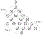
例如,假设一多叉树拓扑网络如图4所示,节点1为出线点,也为根节点,由于节点1至节点20的路径长度最长,因此,将{1,2,4,7,10,14,17,20}作为主干路径。主干路径上存在3个分接点,分别为节点2、节点4和节点10,这三个分接点也分别为三个子树的根节点。For example, assuming a multi-tree topology network as shown in Figure 4,
对于节点2,从其出发只有一条节点路径,因此将该节点路径{3,5}作为节点2对应的枝干路径。For
对于节点4,其除了节点7之外,还有节点6这个子节点,从节点6出发,获取长度最长的节点路径为{6,9,13,16}作为节点4对应的枝干路径;而在枝干路径{6,9,13,16}中,节点6为分接点,其除了节点9之外,还有节点8这个子节点,从节点8出发,将节点路径{8,12}作为节点6对应的枝干路径;而节点8也为分接点,因此将节点路径{11}作为节点8对应的枝干路径。For
同理,对于节点10,其对应的枝干路径为{15,19},节点15也为分接点,其对应的枝干路径为{18}。Similarly, for
S4:确定主干路径的布局方向,并分别根据各分接点所在路径的布局方向,确定各分接点对应的各枝干路径的布局方向。S4: Determine the layout direction of the trunk path, and determine the layout direction of each branch path corresponding to each tap point according to the layout direction of the path where each tap point is located.
具体地,将预设的布局方向作为主干路径的布局方向,并将所述预设的布局方向存储至各主干设备节点的节点信息中。Specifically, the preset layout direction is used as the layout direction of the backbone path, and the preset layout direction is stored in the node information of each backbone device node.
主干路径的布局方向设置完后,通过深度优先搜索遍历所述多叉树拓扑网络中的各设备节点,若当前遍历到的设备节点为分接点,则将当前遍历到的设备节点作为当前分接点;根据当前分接点所在路径的布局方向,均匀地设置当前分接点对应的各枝干路径的布局方向,本实施例中,枝干路径的布局方向与其对应的分接点所在路径的布局方向垂直。After the layout direction of the trunk path is set, traverse each device node in the multi-fork tree topology network through depth-first search, if the currently traversed device node is a tap point, then use the currently traversed device node as the current tap point According to the layout direction of the path where the current tap point is located, evenly set the layout direction of each branch path corresponding to the current tap point. In this embodiment, the layout direction of the branch path is perpendicular to the layout direction of the path where the tap point is located.
也就是说,若当前分接点对应的枝干路径的数量为1,则根据当前分接点所在路径的布局方向,设置当前分接点对应的枝干路径的布局方向,并将所确定的布局方向存储至所述对应的枝干路径中的各枝干设备节点的节点信息中;若当前分接点对应的枝干路径的数量大于或等于2,则根据当前分接点所在路径的布局方向,均匀地设置当前分接点对应的各枝干路径的布局方向,并分别将各枝干路径的布局方向存储至各枝干路径中的各枝干设备节点的节点信息中。That is to say, if the number of branch paths corresponding to the current tap point is 1, then according to the layout direction of the path where the current tap point is located, the layout direction of the branch path corresponding to the current tap point is set, and the determined layout direction is stored In the node information of each branch device node in the corresponding branch path; if the number of branch paths corresponding to the current tap point is greater than or equal to 2, then according to the layout direction of the path where the current tap point is located, evenly set The layout direction of each branch path corresponding to the current tapping point, and storing the layout direction of each branch path in the node information of each branch device node in each branch path.
例如,若分接点所在路径的布局方向为向左或向右,则该分接点对应的枝干路径的布局方向为向上或向下;若分接点所在路径的布局方向为向上或向下,则该分接点对应的枝干路径的布局方向为向左或向右。For example, if the layout direction of the path where the tap point is located is left or right, then the layout direction of the branch path corresponding to the tap point is up or down; if the layout direction of the path where the tap point is located is up or down, then The layout direction of the branch path corresponding to the tap point is left or right.
在步骤S3中,可以得到分接点与枝干路径的映射关系,因此可以得到每个分接点对应的枝干路径的数量。假设某个分接点所在路径的布局方向为向右,且其对应的枝干路径的数量为1,则该枝干路径的布局方向可为向下,也可以为向下;如果该分接点对应的枝干路径的数量为2,则两条枝干路径的布局方向分别为向上和向下;也就是说,如果该分接点对应的枝干路径的数量为偶数,则一半枝干路径的布局方向为向上,另一半枝干路径的布局方向为向下;如果分接点对应的枝干路径的数量为奇数,则在平分的基础上,剩下的一条枝干路径的布局方向可为向下,也可以为向下。例如,假设有5条枝干路径,则其中3条枝干路径的布局方向设为向下,2条枝干路径的布局方向设为向上。以此类推。In step S3, the mapping relationship between tap points and branch paths can be obtained, so the number of branch paths corresponding to each tap point can be obtained. Assuming that the layout direction of the path where a tap point is located is rightward, and the number of corresponding branch paths is 1, the layout direction of the branch path can be downward or downward; if the tap point corresponds to The number of branch paths is 2, and the layout directions of the two branch paths are upward and downward respectively; that is, if the number of branch paths corresponding to the tap point is an even number, then the layout of half of the branch paths The direction of the branch path is upward, and the layout direction of the other half of the branch path is downward; if the number of branch paths corresponding to the tap point is an odd number, then on the basis of equal division, the layout direction of the remaining branch path can be downward. , can also be down. For example, assuming that there are 5 branch paths, the layout direction of 3 branch paths is set downward, and the layout direction of 2 branch paths is set upward. and so on.
S5:根据深度优先搜索的顺序、预设的布局间隔以及主干路径和枝干路径的布局方向,依次放置各设备节点,并通过碰撞检测,对重叠的设备节点进行调整,确定各设备节点的中心坐标。S5: According to the order of depth-first search, the preset layout interval, and the layout direction of the trunk path and branch path, place each device node in turn, and adjust the overlapping device nodes through collision detection to determine the center coordinates of each device node .
具体地,步骤S5包括如下步骤:Specifically, step S5 includes the following steps:
S501:遍历所述主干路径上的主干设备节点,依次将一主干设备节点作为当前主干设备节点。S501: Traverse the backbone device nodes on the backbone path, and use one backbone device node as the current backbone device node in turn.
S502:判断当前主干设备节点是否为第一个主干设备节点,若是,则执行步骤S503,若否,则执行步骤S504。S502: Determine whether the current backbone device node is the first backbone device node, if yes, perform step S503, and if not, perform step S504.
S503:将当前主干设备节点放置在预设的布局起点上,并确定当前主干设备节点的中心坐标。然后执行步骤S505。S503: Place the current backbone device node on a preset starting point of the layout, and determine the center coordinates of the current backbone device node. Then step S505 is executed.
例如,假设预设的布局起点为(0,0),则第一个主干设备节点的中心坐标即为(0,0)。For example, assuming that the preset starting point of the layout is (0,0), the center coordinate of the first backbone device node is (0,0).
S504:根据上一个主干设备节点的中心坐标、主干路径的布局方向以及预设的第一布局间隔,放置当前主干设备节点,并确定当前主干设备节点的中心坐标。然后执行步骤S505。S504: Place the current backbone device node and determine the center coordinates of the current backbone device node according to the center coordinates of the last backbone device node, the layout direction of the backbone path, and the preset first layout interval. Then step S505 is executed.
例如,假设主干路径的布局方向为向右(即X轴正方向),上一个主干设备节点的中心坐标为(x1,0),预设的第一布局间隔为d,则当前主干设备节点的中心坐标为(x1+d,0)。For example, assuming that the layout direction of the trunk path is to the right (that is, the positive direction of the X-axis), the center coordinates of the last trunk device node are (x 1 , 0), and the preset first layout interval is d, then the current trunk device node The center coordinate of is (x 1 +d,0).
S505:根据当前主干设备节点的符号样式信息和设备标注信息,计算当前主干设备节点的图元大小和标注大小,并根据当前主干设备节点的图元大小和标注大小,构建当前主干设备节点对应的最小多边形区域,作为当前主干设备节点的节点区域,同时记录节点区域的上下左右四个方向的边界线段的位置。S505: Calculate the graphic element size and label size of the current backbone device node according to the symbol style information and device label information of the current backbone device node, and construct the corresponding image element size and label size of the current backbone device node The smallest polygonal area is used as the node area of the current backbone device node, and the positions of the boundary line segments in the four directions of up, down, left, and right of the node area are recorded at the same time.
本实施例中,多边形区域由至少一个的矩形区域合并而成。In this embodiment, the polygonal area is formed by merging at least one rectangular area.
其中,在得到第一个主干设备节点的节点区域后,将其作为主干路径的初始路径区域。Wherein, after the node area of the first backbone device node is obtained, it is used as the initial path area of the backbone path.
S506:将当前主干设备节点的节点区域与主干路径的最新路径区域进行碰撞检测,判断是否存在重叠,若是,则执行步骤S507,若否,则执行步骤S510。S506: Perform collision detection between the node area of the current backbone device node and the latest path area of the backbone path, and determine whether there is overlap. If yes, execute step S507; if not, execute step S510.
S507:根据当前主干设备节点的节点区域的边界线路的位置以及主干路径的最新路径区域的边界线段的位置,计算第一边界最大重叠距离。S507: Calculate the maximum overlapping distance of the first boundary according to the position of the boundary line of the node area of the current backbone device node and the position of the boundary line segment of the latest path area of the backbone path.
例如,假设主干路径的布局方向为向右,则可以根据当前主干设备节点的节点区域的左边界线段的位置以及主干路径的最新路径区域的右边界线段的位置,来计算存在重叠的边界线段之间的距离,若存在多个重叠处,则可计算得到多个距离,然后将这些距离中的最大值作为当前主干设备节点的节点区域与主干路径的最新路径区域之间的边界最大重叠距离。For example, assuming that the layout direction of the backbone path is rightward, the position of the border line segment that overlaps can be calculated according to the position of the left boundary line segment of the node area of the current backbone device node and the position of the right boundary line segment of the latest path area of the trunk path. If there are multiple overlaps, multiple distances can be calculated, and then the maximum value of these distances is used as the boundary maximum overlap distance between the node area of the current backbone device node and the latest path area of the backbone path.
S508:根据所述第一边界最大重叠距离以及主干路径的布局方向,对当前主干设备节点的节点区域进行平移,并更新当前主干设备节点的中心坐标及其节点区域的边界线段的位置。S508: Translate the node area of the current backbone device node according to the first boundary maximum overlap distance and the layout direction of the backbone path, and update the center coordinates of the current backbone device node and the position of the boundary segment of the node area.
即将当前主干设备节点的节点区域向主干路径的布局方向平移所述第一边界最大重叠距离,平移后,当前主干设备节点的节点区域与主干路径的最新路径区域之间不重叠,然后将平移后的中心坐标作为当前主干设备节点的中心坐标,并相应更新节点区域的边界线段的位置。That is, the node area of the current backbone device node is translated to the layout direction of the backbone path by the maximum overlap distance of the first boundary. After the translation, the node area of the current backbone device node does not overlap with the latest path area of the backbone path, and then the translated The center coordinates of the current backbone device node are used as the center coordinates of the current backbone device node, and the position of the boundary segment of the node area is updated accordingly.
S509:将平移后的当前主干设备节点的节点区域合并至主干路径的最新路径区域,并将合并后的区域作为主干路径的最新路径区域。然后执行步骤S511。S509: Merge the translated node area of the current backbone device node into the latest path area of the trunk path, and use the merged area as the latest path area of the trunk path. Then step S511 is executed.
S510:将当前主干设备节点的节点区域合并至主干路径的最新路径区域,并将合并后的区域作为主干路径的最新路径区域。然后执行步骤S511。S510: Merge the node area of the current backbone device node into the latest path area of the trunk path, and use the merged area as the latest path area of the trunk path. Then step S511 is executed.
也就是说,如果当前主干设备节点的节点区域与主干路径的最新路径区域不重叠,则直接将当前主干设备节点的节点区域合并到主干路径的最新路径区域中,如果重叠,则调整当前主干设备节点的节点区域后,再将其合并到主干路径的最新路径区域中。That is to say, if the node area of the current backbone device node does not overlap with the latest path area of the trunk path, the node area of the current backbone device node is directly merged into the latest path area of the trunk path, and if it overlaps, the current backbone device is adjusted After the node area of the node is merged into the newest path area of the trunk path.
S511:判断当前主干设备节点是否为分接点,若是,则执行步骤S512,若否,则执行步骤S518。S511: Judging whether the current backbone equipment node is a tapping point, if yes, execute step S512, if not, execute step S518.
S512:分别对当前主干设备节点对应的枝干路径中的各枝干设备节点进行布局,得到当前主干设备节点对应的枝干路径的路径区域。S512: Lay out each branch device node in the branch path corresponding to the current trunk device node respectively, to obtain a path area of the branch path corresponding to the current trunk device node.
S513:将当前主干设备节点对应的枝干路径的路径区域与主干路径的最新路径区域进行碰撞检测,判断是否存在重叠,若是,则执行步骤S514,若否,则执行步骤S517。S513: Perform collision detection between the path area of the branch path corresponding to the current backbone device node and the latest path area of the trunk path, and determine whether there is overlap. If yes, execute step S514; if not, execute step S517.
S514:对当前主干设备节点对应的枝干路径的路径区域以及当前主干设备节点的节点区域进行调整,并更新当前主干设备节点的中心坐标及其节点区域的边界线段的位置以及当前主干设备节点对应的枝干路径上的各枝干设备节点的中心坐标及其节点区域的边界线段的位置。S514: Adjust the path area of the branch path corresponding to the current backbone device node and the node area of the current backbone device node, and update the center coordinates of the current backbone device node and the position of the boundary line segment of the node area and the corresponding position of the current backbone device node The center coordinates of each branch device node on the branch path and the position of the boundary segment of the node area.
具体地,本实施例中,根据当前主干设备节点对应的枝干路径的路径区域的边界线路的位置以及主干路径的最新路径区域的边界线段的位置,计算第二边界最大重叠距离,然后根据所述第二边界最大重叠距离以及所述主干路径的布局方向,对当前主干设备节点对应的枝干路径的路径区域以及当前主干设备节点的节点区域进行平移,并更新当前主干设备节点的中心坐标及其节点区域的边界线段的位置以及当前主干设备节点对应的枝干路径上的各枝干设备节点的中心坐标及其节点区域的边界线段的位置。Specifically, in this embodiment, according to the position of the boundary line of the path area of the branch path corresponding to the current backbone device node and the position of the boundary line segment of the latest path area of the trunk path, the second boundary maximum overlapping distance is calculated, and then according to the The maximum overlapping distance of the second border and the layout direction of the trunk path are used to translate the path area of the branch path corresponding to the current trunk device node and the node area of the current trunk device node, and update the center coordinates and The position of the boundary line segment of its node area, the center coordinates of each branch device node on the branch path corresponding to the current backbone device node, and the position of the boundary line segment of the node area.
例如,如图5所示,图中的B1区域为主干路径的最新路径区域,B2区域为当前主干设备节点对应的枝干路径的路径区域,其中,Lc和Ld为B2区域的左边界线段,La和Lb为B1区域右边界线段,由于La和Lc之间的距离大于Lb和Ld之间的距离,因此,将当前主干设备节点对应的枝干路径的路径区域以及当前主干设备节点的节点区域向右平移La-Lc。For example, as shown in Figure 5, the B1 area in the figure is the latest path area of the trunk path, and the B2 area is the path area of the branch path corresponding to the current trunk device node, where Lc and Ld are the left boundary line segments of the B2 area, La and Lb are the right boundary line segments of the B1 area. Since the distance between La and Lc is greater than the distance between Lb and Ld, the path area of the branch path corresponding to the current backbone device node and the node area of the current backbone device node Pan La-Lc right.
在其他可选的实施例中,若当前主干设备节点对应的枝干路径中存在分接点,且该分接点对应的枝干路径的数量为1,则可将该分接点对应的枝干路径的布局方向修改为相反方向,并更新该分接点对应的枝干路径中的各枝干设备节点的中心坐标及其节点区域的边界线段的位置,同时更新当前主干设备节点对应的枝干路径的路径区域,然后将更新后的当前主干设备节点对应的枝干路径的路径区域与主干路径的最新路径区域进行碰撞检测,判断是否存在重叠,若不重叠,则保留对布局方向的修改,若还是重叠,则放弃对布局方向的修改,还是采用上述基于最大重叠距离进行平移的方法。若当前主干设备节点对应的枝干路径中的分接点对应的枝干路径的数量大于1,也采用上述基于最大重叠距离进行平移的方法。In other optional embodiments, if there is a tap point in the branch path corresponding to the current backbone device node, and the number of the branch path corresponding to the tap point is 1, then the branch path corresponding to the tap point can be Modify the layout direction to the opposite direction, and update the center coordinates of each branch device node in the branch path corresponding to the tap point and the position of the boundary segment of the node area, and update the path of the branch path corresponding to the current trunk device node area, and then perform collision detection between the path area of the branch path corresponding to the updated current backbone device node and the latest path area of the trunk path to determine whether there is overlap. If there is no overlap, keep the modification of the layout direction, and if it still overlaps , then give up the modification of the layout direction, or use the above-mentioned method of translation based on the maximum overlapping distance. If the number of branch paths corresponding to the tap points in the branch paths corresponding to the current backbone device node is greater than 1, the above-mentioned method of performing translation based on the maximum overlapping distance is also adopted.
例如,如图6-7所示,假设当前遍历到的主干设备节点为节点7,则节点1-7所形成的区域为主干路径的最新路径区域,节点8、9、10、11、15所形成的区域为当前主干设备节点对应的枝干路径的路径区域,可以看出,节点9和节点10与主干路径的最新路径区域存在重叠,图6中采用平移的方式消除重叠,图7中通过将节点8的枝干路径{9,10}的布局方向由向左修改为向右,修改后就不与主干路径的最新路径区域重叠。For example, as shown in Figure 6-7, assuming that the currently traversed backbone device node is
相比起将节点7以及节点8、9、10、11、15同时向右平移的方案,该方法可进一步避免画布留白,使得节点布局尽可能地紧凑。Compared with the scheme of moving
S515:根据调整后的当前主干设备节点的节点区域以及当前主干设备节点对应的枝干路径的路径区域,更新主干路径的最新路径区域,并将更新后的区域作为主干路径的最新路径区域。然后执行步骤S517。S515: Update the latest path area of the trunk path according to the adjusted node area of the current backbone device node and the path area of the branch path corresponding to the current backbone device node, and use the updated area as the latest path area of the trunk path. Then execute step S517.
S516:将当前主干设备节点对应的枝干路径的枝干路径区域合并至主干路径的最新路径区域,并将合并后的区域作为主干路径的最新路径区域。然后执行步骤S517。S516: Merge the branch path area of the branch path corresponding to the current trunk device node into the latest path area of the trunk path, and use the merged area as the latest path area of the trunk path. Then execute step S517.
S517:判断是否遍历完所述主干路径上的主干设备节点,若是,若是,则执行步骤S518,若否,则继续遍历主干路径上的主干设备节点,将下一主干设备节点作为当前主干设备节点,即继续执行步骤S501。S517: Determine whether the backbone device nodes on the trunk path have been traversed, if yes, then execute step S518, if not, continue to traverse the backbone device nodes on the trunk path, and use the next backbone device node as the current backbone device node , that is, continue to execute step S501.
S518:根据主干路径的最新路径区域,确定各设备节点的中心坐标。S518: Determine the center coordinates of each device node according to the latest path area of the trunk path.
其中,对于步骤S512,即每当遍历到分接点时,优先对分接点对应的枝干路径上的枝干设备节点进行布局,布局完后,得到枝干路径的路径区域,并与分接点所在路径的路径区域合并后,再对分接点的下一设备节点进行布局。若枝干路径上也存在分接点,也采用相同的方法递归地先得到分接点对应的枝干路径的路径区域。Among them, for step S512, that is, whenever a tap point is traversed, the branch device nodes on the branch path corresponding to the tap point are preferentially laid out. After the path areas of the path are merged, the next device node of the tap point is laid out. If there is also a tap point on the branch path, the same method is used to recursively obtain the path area of the branch path corresponding to the tap point.
具体地,将当前遍历到的分接点作为当前分接点,步骤S512具体包括如下步骤:Specifically, taking the currently traversed tap point as the current tap point, step S512 specifically includes the following steps:
S5001:遍历当前分接点对应的一枝干路径的枝干设备节点,依次将一枝干设备节点作为当前枝干设备节点。S5001: Traverse the branch device nodes of a branch path corresponding to the current tapping point, and sequentially use one branch device node as the current branch device node.
S5002:判断当前枝干设备节点是否为所述一枝干路径的第一个枝干设备节点,若是,则执行步骤S5003,若否,则执行步骤S5010。S5002: Determine whether the current branch device node is the first branch device node of the one branch path, if yes, perform step S5003, and if not, perform step S5010.
S5003:根据当前分接点的中心坐标、所述一枝干路径的布局方向以及预设的第一布局间隔,放置当前枝干设备节点,并确定当前枝干设备节点的中心坐标。S5003: Place the current branch device node and determine the center coordinate of the current branch device node according to the center coordinate of the current tap point, the layout direction of the branch path and the preset first layout interval.
S5004:根据当前枝干设备节点的符号样式信息和设备标注信息,计算当前枝干设备节点的图元大小和标注大小,并根据当前枝干设备节点的图元大小和标注大小,构建当前枝干设备节点对应的最小多边形区域,作为当前枝干设备节点的节点区域,同时记录节点区域的上下左右四个方向的边界线段的位置。S5004: Calculate the primitive size and label size of the current branch device node according to the symbol style information and device label information of the current branch device node, and construct the current branch according to the primitive size and label size of the current branch device node The minimum polygonal area corresponding to the device node is used as the node area of the current branch device node, and the positions of the boundary line segments in the four directions of up, down, left, and right of the node area are recorded at the same time.
S5005:将当前枝干设备节点的节点区域与当前分接点的节点区域进行碰撞检测,判断是否存在重叠,若是,则执行步骤S5006,若否,则执行步骤S5009。S5005: Perform collision detection between the node area of the current branch device node and the node area of the current tap point, and determine whether there is overlap. If yes, execute step S5006; if not, execute step S5009.
S5006:根据当前枝干设备节点的节点区域的边界线路的位置以及当前分接点的节点区域的边界线段的位置,计算第三边界最大重叠距离。S5006: Calculate the maximum overlapping distance of the third boundary according to the position of the boundary line of the node area of the current branch device node and the position of the boundary line segment of the node area of the current tapping point.
S5007:根据所述第三边界最大重叠距离以及所述一枝干路径的布局方向,对当前枝干设备节点的节点区域进行平移,并更新当前枝干设备节点的中心坐标及其节点区域的边界线段的位置。S5007: Translate the node area of the current branch device node according to the maximum overlapping distance of the third boundary and the layout direction of the branch path, and update the center coordinates of the current branch device node and the boundary line segment of the node area s position.
即将当前枝干设备节点的节点区域沿着所述一枝干路径的布局方向平移第三边界最大重叠距离。That is, the node area of the current branch device node is translated along the layout direction of the branch path by the maximum overlapping distance of the third boundary.
S5008:将更新后的当前枝干设备节点的节点区域作为所述一枝干路径的初始路径区域。然后执行步骤S5017。S5008: Use the updated node area of the current branch device node as the initial path area of the one branch path. Then execute step S5017.
S5009:将当前枝干设备节点的节点区域作为所述一枝干路径的初始路径区域。然后执行步骤S5017。S5009: Use the node area of the current branch device node as the initial path area of the one branch path. Then execute step S5017.
S5010:根据上一个枝干设备节点的中心坐标、所述一枝干路径的布局方向以及预设的第一布局间隔,放置当前枝干设备节点,并确定当前枝干设备节点的中心坐标。S5010: Place the current branch device node and determine the center coordinates of the current branch device node according to the center coordinate of the last branch device node, the layout direction of the branch path and the preset first layout interval.
S5011:根据当前枝干设备节点的符号样式信息和设备标注信息,计算当前枝干设备节点的图元大小和标注大小,并根据当前枝干设备节点的图元大小和标注大小,构建当前枝干设备节点对应的最小多边形区域,作为当前枝干设备节点的节点区域,同时记录节点区域的上下左右四个方向的边界线段的位置。S5011: Calculate the primitive size and label size of the current branch device node according to the symbol style information and device label information of the current branch device node, and construct the current branch according to the primitive size and label size of the current branch device node The minimum polygonal area corresponding to the device node is used as the node area of the current branch device node, and the positions of the boundary line segments in the four directions of up, down, left, and right of the node area are recorded at the same time.
S5012:将当前枝干设备节点的节点区域与所述一枝干路径的最新路径区域进行碰撞检测,判断是否存在重叠,若是,则执行步骤S5013,若否,则执行步骤S5016。S5012: Perform collision detection between the node area of the current branch device node and the latest path area of the branch path, and determine whether there is overlap. If yes, execute step S5013; if not, execute step S5016.
S5013:根据当前枝干设备节点的节点区域的边界线路的位置以及所述一枝干路径的最新路径区域的边界线段的位置,计算第四边界最大重叠距离。S5013: According to the position of the boundary line of the node area of the current branch device node and the position of the boundary line segment of the latest path area of the one branch path, calculate the fourth maximum overlapping distance of the boundary.
S5014:根据所述第四边界最大重叠距离以及所述一枝干路径的布局方向,对当前枝干设备节点的节点区域进行平移,并更新当前枝干设备节点的中心坐标及其节点区域的边界线段的位置。S5014: Translate the node area of the current branch device node according to the fourth boundary maximum overlapping distance and the layout direction of the branch path, and update the center coordinates of the current branch device node and the boundary line segment of the node area s position.
即将当前枝干设备节点的节点区域沿着所述一枝干路径的布局方向平移第四边界最大重叠距离。That is, the node area of the current branch device node is shifted along the layout direction of the branch path by the fourth boundary maximum overlap distance.
S5015:将平移后的当前枝干设备节点的节点区域合并至所述一枝干路径的最新路径区域,并将合并后的区域作为所述一枝干路径的最新路径区域。然后执行步骤S5017。S5015: Merge the translated node area of the current branch device node into the latest path area of the one branch path, and use the merged area as the latest path area of the one branch path. Then execute step S5017.
S5016:将当前枝干设备节点的节点区域合并至所述一枝干路径的最新路径区域,并将合并后的区域作为所述一枝干路径的最新路径区域。然后执行步骤S5017。S5016: Merge the node area of the current branch device node into the latest path area of the one branch path, and use the merged area as the latest path area of the one branch path. Then execute step S5017.
S5017:判断当前枝干设备节点是否为分接点,若是,则执行步骤S5018,若否,则执行步骤S5019。S5017: Determine whether the current branch device node is a tapping point, if yes, execute step S5018, if not, execute step S5019.
S5018:递归地对当前枝干设备节点对应的各枝干路径中的各枝干设备进行点进行布局,得到当前枝干设备节点对应的各枝干路径的路径区域。然后执行步骤S5019。S5018: Recursively perform point layout on each branch device in each branch path corresponding to the current branch device node, and obtain the path area of each branch path corresponding to the current branch device node. Then execute step S5019.
S5019:判断当前枝干设备节点是否为所述一枝干路径的最后一个枝干设备节点,若是,则执行步骤S5020,若否,则继续遍历所述一枝干路径的枝干设备节点,获取下一枝干设备节点作为当前枝干设备节点,即继续执行步骤S5001。S5019: Determine whether the current branch device node is the last branch device node of the one branch path, if yes, perform step S5020, if not, continue to traverse the branch device nodes of the one branch path, and obtain the next branch The trunk device node serves as the current branch device node, that is, continue to execute step S5001.
S5020:分别将所述一枝干路径中的各分接点对应的各枝干路径的路径区域与所述一枝干路径的最新路径区域进行碰撞检测,判断是否存在重叠,若是,则执行步骤S5021,若否,则执行步骤S5023。S5020: Carry out collision detection between the path area of each branch path corresponding to each tap point in the one branch path and the latest path area of the one branch path, and judge whether there is overlap, if so, execute step S5021, if If not, execute step S5023.
此时,由于已遍历完所述一枝干路径的枝干设备节点,因此,此时所述一枝干路径的路径区域包含所述一枝干路径的所有枝干设备节点的节点区域,但还未包含所述一枝干路径上的分界点对应的枝干路径的路径区域。At this time, since the branch device nodes of the one branch path have been traversed, the path area of the one branch path includes the node areas of all the branch device nodes of the one branch path at this time, but does not contain The path area of the branch path corresponding to the boundary point on the branch path.
本步骤中,可依次将所述一枝干路径中的各分接点对应的各枝干路径与所述一枝干路径的最新路径区域进行碰撞检测,若检测到有某个分接点对应的某条枝干路径的路径区域与所述一枝干路径的最新路径区域存在重叠,则后续可对该分接点及其对应的该枝干路径进行调整。In this step, each branch path corresponding to each tap point in the one branch path can be sequentially subjected to collision detection with the latest path area of the one branch path, if a certain branch corresponding to a certain tap point is detected If the path area of the trunk path overlaps with the latest path area of the branch path, then the tap point and the corresponding branch path can be adjusted subsequently.
S5021:对与所述一枝干路径的最新路径区域存在重叠的所述一枝干路径中的一分接点对应的枝干路径的路径区域进行调整,并更新所述一分接点的中心坐标及其节点区域的边界线段的位置以及所述一分接点对应的枝干路径中的各枝干设备节点的中心坐标及其节点区域的边界线段的位置。S5021: Adjust the path area of the branch path corresponding to a branch point in the branch path that overlaps with the latest path area of the branch path, and update the center coordinates of the branch point and its nodes The position of the boundary line segment of the area, the center coordinates of each branch device node in the branch path corresponding to the tap point, and the position of the boundary line segment of the node area.
本步骤可参照上述步骤S514。For this step, refer to the above step S514.
具体地,本实施例中,根据所述一分接点对应的枝干路径的路径区域的边界线路的位置以及所述一枝干路径的最新路径区域的边界线段的位置,计算第五边界最大重叠距离;然后根据所述第五边界最大重叠距离以及所述一枝干路径的布局方向,对所述一分接点的节点区域以及所述一分接点对应的枝干路径的路径区域进行平移,并更新所述一分接点的中心坐标及其节点区域的边界线段的位置以及所述一分接点对应的枝干路径中的各枝干设备节点的中心坐标及其节点区域的边界线段的位置。Specifically, in this embodiment, the fifth boundary maximum overlap distance is calculated according to the position of the boundary line of the path area of the branch path corresponding to the branch point and the position of the boundary line segment of the latest path area of the branch path ; then according to the fifth boundary maximum overlapping distance and the layout direction of the branch path, the node area of the tap point and the path area of the branch path corresponding to the tap point are translated, and the updated The central coordinates of a tap point and the position of the boundary line segment of its node area, and the center coordinates of each branch device node in the branch path corresponding to the tap point and the position of the boundary line segment of its node area.
在另一个实施例中,可先获取所述一分接点对应的枝干路径的数量,若数量为1,则将所述一分接点对应的枝干路径的布局方向修改为相反方向,并更新所述一分接点对应的枝干路径中的各枝干设备节点的中心坐标及其节点区域的边界线段的位置;然后将布局方向修改后的所述一分接点对应的枝干路径的路径区域与所述一枝干路径的最新路径区域进行碰撞检测,若不重叠,则保留布局方向修改,若重叠,则还是采用上述基于最大重叠距离进行平移的方法。若所述一分接点对应的枝干路径的数量大于1,也采用上述基于最大重叠距离进行平移的方法。In another embodiment, the number of branch paths corresponding to the one tap point can be obtained first, and if the number is 1, the layout direction of the branch path corresponding to the one tap point is modified to the opposite direction, and the updated The central coordinates of each branch device node in the branch path corresponding to the one tap point and the position of the boundary line segment of the node area; then the path area of the branch path corresponding to the one tap point after the layout direction is modified Perform collision detection with the latest path area of the branch path. If there is no overlap, the layout direction modification will be retained. If overlap, the above-mentioned method of translation based on the maximum overlapping distance will still be used. If the number of branch paths corresponding to the tap point is greater than 1, the above-mentioned method of performing translation based on the maximum overlapping distance is also adopted.
S5022:根据调整后的所述一分接点的节点区域以及所述一分接点对应的枝干路径的路径区域,更新所述一枝干路径的最新路径区域,并将更新后的区域作为所述一枝干路径的最新路径区域。S5022: Update the latest path area of the branch path according to the adjusted node area of the tap point and the path area of the branch path corresponding to the tap point, and use the updated area as the branch path The latest path region of the dry path.
S5023:将与所述一枝干路径的最新路径区域不存在重叠的所述一枝干路径中的一分接点对应的枝干路径的路径区域合并至所述一枝干路径的最新路径区域,并将合并后的区域作为所述一枝干路径的最新路径区域。S5023: Merge the path area of the branch path corresponding to a tap point in the one branch path that does not overlap with the latest path area of the one branch path into the latest path area of the one branch path, and merge the The latter area is used as the latest path area of the branch path.
进一步地,如果所述一枝干路径中存在多个分接点,则依次对各分接点对应的枝干路径进行遍历判断,并将合并了所有分接点对应的枝干路径的路径区域的所述一枝干路径的最新路径区域,作为所述一枝干路径的路径区域。当所述一枝干路径对应的分接点所在路径的设备节点遍历完后,再将所述一枝干路径的路径区域与其对应的分接点所在路径的路径区域进行碰撞检测。Further, if there are multiple branch points in the one branch path, the branch path corresponding to each branch point is traversed and judged sequentially, and the branch path of the path area of the branch path corresponding to all the branch points is merged. The latest path area of the trunk path is used as the path area of the branch path. After the device nodes of the path where the tap point corresponding to the one branch path is traversed, a collision detection is performed between the path area of the one branch path and the path area of the path corresponding to the tap point.
进一步地,若当前分接点对应的枝干路径的数量大于1,则根据上述步骤,依次对各枝干路径进行遍历布局。Further, if the number of branch paths corresponding to the current tapping point is greater than 1, according to the above steps, traverse layout is performed on each branch path in sequence.
其中,若当前分接点对应的枝干路径的数量大于2,则将当前分接点对应的同一布局方向的枝干路径中,第一个进行布局的枝干路径的第一个枝干设备节点放置于垂直当前分接点所在路径且垂点为当前分接点的垂线上,其他枝干路径的第一个枝干设备节点,根据预设的第二布局间隔,依次放置于已布局的枝干路径的第一个枝干设备节点沿着所述同一布局方向的两侧。其中,第二布局间隔可与第一布局间隔相同,也可不相同。Among them, if the number of branch paths corresponding to the current tap point is greater than 2, among the branch paths corresponding to the current tap point in the same layout direction, the first branch device node of the first branch path for layout is placed On the vertical line perpendicular to the path where the current tap point is located and the vertical point is the current tap point, the first branch device nodes of other branch paths are placed on the laid out branch paths in sequence according to the preset second layout interval The first branch device node is on both sides along the same layout direction. Wherein, the second layout interval may be the same as or different from the first layout interval.
例如,如图8所示,在左侧的图中,节点3为分接点,其对应的枝干路径的数量为2,因此两条枝干路径的第一个枝干设备节点——节点6和节点3放置在垂直于路径{1,2,3,7}的布局方向,且垂点为节点3的垂线上;在右侧的图中,节点3为分接点,其对应的枝干路径的数量为5,其中,枝干路径{6}和{9,10}的布局方向相同,枝干路径{4,5}、{11,12}和{7,8}的布局方向相同,那么对于枝干路径{6}和{9,10},第一个进行布局的枝干路径为{6},将其中的第一个枝干设备节点——节点6放置在垂直于路径{1,2,3,13}的布局方向,且垂点为节点3的垂线上,第二个进行布局的枝干路径为{9,10},将其中的第一个枝干设备节点——节点9放置在节点6沿着其布局方向的一侧(图中放置在节点6的左侧)。同理,对于枝干路径{4,5}、{11,12}和{7,8},节点4放置在垂直于路径{1,2,3,13}的布局方向,且垂点为节点3的垂线上,节点11和节点7分别放置于节点4沿着其布局方向的两侧。For example, as shown in Figure 8, in the figure on the left, node 3 is a tap point, and the number of corresponding branch paths is 2, so the first branch device node of the two branch paths—node 6 and node 3 are placed perpendicular to the layout direction of the path {1,2,3,7}, and the vertical point is the vertical line of node 3; in the figure on the right, node 3 is a tap point, and its corresponding branch The number of paths is 5, among which, the layout directions of the branch paths {6} and {9,10} are the same, and the layout directions of the branch paths {4,5}, {11,12} and {7,8} are the same, Then for the branch paths {6} and {9,10}, the first branch path for layout is {6}, and the first branch device node, node 6, is placed perpendicular to the path {1 ,2,3,13}, and the vertical point is the vertical line of node 3, the second branch path for layout is {9,10}, and the first branch device node among them—— Node 9 is placed on the side of node 6 along its layout direction (it is placed on the left side of node 6 in the figure). Similarly, for the branch paths {4,5}, {11,12} and {7,8},
对于步骤S5,假设最终得到的布局图如图6中的右侧图所示,那么节点的放置顺序如下:For step S5, assuming that the final layout diagram is as shown in the right diagram in Figure 6, the placement order of the nodes is as follows:
先放置节点1,并生成节点1的节点区域,由于节点1不为分接点,因此将节点1的节点区域作为主干路径的初始路径区域。
然后放置节点2,并生成节点2的节点区域,由于节点2不为分接点,因此将节点2的节点区域合并至主干路径的最新路径区域(此时即为节点1的节点区域)。Then
然后放置节点3,并生成节点3的节点区域,由于节点3为分接点,因此,先将节点3的节点区域(或平移后的节点3的节点区域)合并至主干路径的最新路径区域中。Then
接着放置节点4,并生成节点4的节点区域,将节点4的节点区域与节点3的节点区域进行碰撞检测,根据检测结果调整或不调整节点4的节点区域,然后将节点4的节点区域作为枝干路径{4,5}的初始路径区域。接着放置节点5,并生成节点5的节点区域,将节点5的节点区域与枝干路径{4,5}的最新路径区域(此时即为节点4的节点区域)进行碰撞检测,根据检测结果调整或不调整节点5的节点区域,然后将节点5的节点区域合并至枝干路径{4,5}的最新路径区域。由于节点5是枝干路径{4,5}中的最后一个枝干设备节点,因此此时即可得到枝干路径{4,5}的路径区域,然后将其与主干路径的最新路径区域(此时即为路径{1,2,3}对应的区域)进行碰撞检测,根据检测结果调整或不调整枝干路径{4,5}的路径区域,最后将枝干路径{4,5}的路径区域合并至主干路径的最新路径区域,合并后,主干路径的最新路径区域为{1,2,3,4,5}对应的区域。Then
接着放置节点3的另一条枝干路径{6}中的节点6,同理,进行放置、碰撞检测、(调整、)合并后,主干路径的最新路径区域为{1,2,3,4,5,6}对应的区域。Then
然后放置节点7,并生成节点7的节点区域,由于节点7为分接点,因此,先将节点7的节点区域(或平移后的节点7的节点区域)合并至主干路径的最新路径区域中。Then
然后放置节点8,并生成节点8的节点区域,将节点8的节点区域与节点7的节点区域进行碰撞检测后,将节点8的节点区域作为枝干路径{8,11,15}的初始路径区域。Then
然后参照上述描述,依次放置节点9和节点10,生成枝干路径{9,10}的路径区域,然后将其与枝干路径{8,11,15}的最新路径区域(此时即为节点8的节点区域)进行碰撞检测,根据检测结果调整或不调整枝干路径{9,10}的路径区域,最后将枝干路径{9,10}的路径区域合并至枝干路径{8,11,15}的最新路径区域(此时即为节点8的节点区域)中,合并后,枝干路径{8,11,15}的最新路径区域即为{8,9,10}对应的区域。Then referring to the above description,
然后参照上述描述,继续放置枝干路径{8,11,15}中的节点11和节点15,生成枝干路径{8,11,15}的路径区域(此时即为{8,9,10,11,15}对应的区域),将其与主干路径的最新路径区域(此时即为{1,2,3,4,5,6,7}对应的区域)进行碰撞检测,根据检测结果调整或不调整枝干路径该枝干路径的路径区域,最后将其合并至主干路径的最新路径区域,合并后,主干路径的最新路径区域为{1,2,3,4,5,6,7,8,9,10,11,15}对应的区域。Then referring to the above description, continue to place
以此类推,依次放置节点12、节点13和节点14,当布局完节点14后,此时主干路径的最新路径区域即为{1,2,3,4,5,6,7,8,9,10,11,15,12,13,14}对应的区域,并可得到各设备节点的中心坐标。By analogy,
S6:分别根据各设备节点的中心坐标和设备端子偏移量,计算各设备节点的端子坐标,并根据所述多叉树拓扑网络以及各设备节点的端子坐标,进行设备节点之间的连接布线,得到布局图。S6: Calculate the terminal coordinates of each device node according to the center coordinates and device terminal offsets of each device node, and perform connection and wiring between device nodes according to the multi-fork tree topology network and the terminal coordinates of each device node , to get the layout diagram.
具体地,根据多叉树拓扑网络获取设备端子间的连接关系,并根据计算得到的各设备节点的端子坐标,对设备端子进行连线,实现设备间的连接布线。Specifically, the connection relationship between equipment terminals is obtained according to the multi-fork tree topology network, and the equipment terminals are connected according to the calculated terminal coordinates of each equipment node, so as to realize the connection and wiring between equipment.
进一步地,布局完成后,生成JSON数据模型信息,保存至数据库中,并传回至应用端进行图形展示。Further, after the layout is completed, generate JSON data model information, save it in the database, and send it back to the application side for graphical display.
图9示出了图1-2中的示例经过本实施例的方法处理后的处理效果,可以看出,本实施例的方法可使布局更加紧凑美观,消除了线路重叠的问题,同时,在布局的过程中考虑了设备标注,消除了标注冲突压盖的问题。Figure 9 shows the processing effect of the example in Figure 1-2 after being processed by the method of this embodiment. It can be seen that the method of this embodiment can make the layout more compact and beautiful, and eliminate the problem of overlapping lines. During the layout process, equipment labels are considered, which eliminates the problem of label conflict and capping.
本实施例从地理图中抽取的线路数据,将线路数据分成设备数据和样式数据,并通过JSON描述构成电网的设备对象及其相互关系,包括设备图元符号、设备标注信息、网络拓扑连接关系等,通过对JSON数据的解析,创建设备树节点并构建节点间的关系,在内存中形成多叉树的拓扑模型结构。再结合正向递归、反向递归布局算法和干线支线算法的优点,对树节点引入边界区域的方式描述设备和标注的布局区域,并将标注区域纳入到设备布局区域中,先通过正向递归布置节点,再通过反向递归布置枝干,接着通过设备区域之间进行碰撞检测,对有碰撞区域的进行处理,消除重叠。再通过边界合并的方式将设备区域递归的合并到统一布局区域中,形成一个整体,最终消除所有重叠而不引入新的重叠。同时为保证布线时,尽可能地减少路径交叉的情况出线,在图元布局时就计算图元间的最佳布线路径,及时调整排布顺序,在不引入新的布线算法影响运行时长的同时还能保证布线路径合理美观。This embodiment divides the line data into equipment data and style data from the line data extracted from the geographic map, and describes the equipment objects constituting the power grid and their mutual relationships through JSON, including equipment graphic element symbols, equipment label information, and network topology connection relationships etc., through parsing the JSON data, create device tree nodes and build relationships between nodes, forming a multi-tree topology model structure in memory. Combined with the advantages of forward recursion, reverse recursion layout algorithm and trunk branch algorithm, introduce the border area to the tree node to describe the layout area of equipment and labels, and incorporate the label area into the equipment layout area, first through forward recursion Arrange the nodes, and then arrange the branches through reverse recursion, and then perform collision detection between the equipment areas, and process the areas with collisions to eliminate overlaps. Then recursively merge the device area into the unified layout area by means of boundary merging to form a whole, and finally eliminate all overlaps without introducing new overlaps. At the same time, in order to ensure that when routing, the situation of crossing paths should be reduced as much as possible, and the optimal routing path between primitives will be calculated when the primitives are laid out, and the arrangement sequence will be adjusted in time, without introducing new routing algorithms to affect the running time. It can also ensure that the wiring path is reasonable and beautiful.
实施例二Embodiment two
本实施例是对应上述实施例的一种计算机可读存储介质,其上存储有计算机程序,所述程序被处理器执行时实现如上述实施例中基于多叉树碰撞检测的配网专题图布局方法的各个步骤,且能达到相同的技术效果,此处不再累述。This embodiment is a computer-readable storage medium corresponding to the above-mentioned embodiments, on which a computer program is stored, and when the program is executed by a processor, the distribution network thematic map layout based on multi-tree collision detection in the above-mentioned embodiments is realized Each step of the method, and can achieve the same technical effect, will not be repeated here.
综上所述,本发明提供的一种基于多叉树碰撞检测的配网专题图布局方法及存储介质,通过碰撞检测,对存在重叠的区域进行调整,从而可消除线路重叠的问题;通过构建多叉树拓扑网络,并确定多叉树拓扑网络中的主干路径以及各分接点对应的枝干路径,使得后续可依据一定的顺序进行正向递归布置节点以及反向递归布置枝干,从而可在消除重叠的同时不引入新的重叠;并且,在布局过程中考虑了电网设备的标准信息,可消除标注冲突压盖的问题。In summary, the present invention provides a distribution network thematic map layout method and storage medium based on multi-tree collision detection. Through collision detection, overlapping areas can be adjusted, thereby eliminating the problem of overlapping lines; by constructing Multi-fork tree topology network, and determine the trunk path in the multi-fork tree topology network and the branch path corresponding to each branch point, so that the forward recursive arrangement of nodes and the reverse recursive arrangement of branches can be carried out subsequently according to a certain order, so that While eliminating overlaps, new overlaps are not introduced; moreover, the standard information of grid equipment is considered in the layout process, which can eliminate the problem of labeling conflicts and covering.
以上所述仅为本发明的实施例,并非因此限制本发明的专利范围,凡是利用本发明说明书及附图内容所作的等同变换,或直接或间接运用在相关的技术领域,均同理包括在本发明的专利保护范围内。The above description is only an embodiment of the present invention, and does not limit the patent scope of the present invention. All equivalent transformations made by using the description of the present invention and the contents of the accompanying drawings, or directly or indirectly used in related technical fields, are all included in the same principle. Within the scope of patent protection of the present invention.
Claims (9)
Priority Applications (1)
| Application Number | Priority Date | Filing Date | Title |
|---|---|---|---|
| CN202211428241.7A CN115688341B (en) | 2022-11-15 | 2022-11-15 | Distribution network thematic map layout method based on multi-tree collision detection and storage medium |
Applications Claiming Priority (1)
| Application Number | Priority Date | Filing Date | Title |
|---|---|---|---|
| CN202211428241.7A CN115688341B (en) | 2022-11-15 | 2022-11-15 | Distribution network thematic map layout method based on multi-tree collision detection and storage medium |
Publications (2)
| Publication Number | Publication Date |
|---|---|
| CN115688341A true CN115688341A (en) | 2023-02-03 |
| CN115688341B CN115688341B (en) | 2024-04-16 |
Family
ID=85051696
Family Applications (1)
| Application Number | Title | Priority Date | Filing Date |
|---|---|---|---|
| CN202211428241.7A Active CN115688341B (en) | 2022-11-15 | 2022-11-15 | Distribution network thematic map layout method based on multi-tree collision detection and storage medium |
Country Status (1)
| Country | Link |
|---|---|
| CN (1) | CN115688341B (en) |
Cited By (2)
| Publication number | Priority date | Publication date | Assignee | Title |
|---|---|---|---|---|
| CN115866071A (en) * | 2023-02-28 | 2023-03-28 | 中信云网有限公司 | Method and device for determining reporting path of initial equipment attribute information |
| CN121051917A (en) * | 2025-11-03 | 2025-12-02 | 苏州银蕨电力科技有限公司 | A method for automatically drawing the topology map for fault assessment in a distribution network |
Citations (18)
| Publication number | Priority date | Publication date | Assignee | Title |
|---|---|---|---|---|
| US6898773B1 (en) * | 2002-01-22 | 2005-05-24 | Cadence Design Systems, Inc. | Method and apparatus for producing multi-layer topological routes |
| US20050166169A1 (en) * | 2004-01-27 | 2005-07-28 | Kurzum Zahi M. | Method for legalizing the placement of cells in an integrated circuit layout |
| US20070240086A1 (en) * | 2006-03-31 | 2007-10-11 | Synopsys, Inc. | Range pattern definition of susceptibility of layout regions to fabrication issues |
| CN103150425A (en) * | 2013-02-06 | 2013-06-12 | 上海交通大学 | Automatic generation method used for single line diagram of distribution network and based on topological hierarchy |
| US20150012902A1 (en) * | 2013-07-03 | 2015-01-08 | State Grid Corporation Of China | Automatic mapping method for a distribution network based on logical layout |
| CN104951844A (en) * | 2015-05-21 | 2015-09-30 | 北京科东电力控制系统有限责任公司 | Layout optimization method of distribution network thematic maps |
| CN105117518A (en) * | 2015-07-28 | 2015-12-02 | 山东大学 | Automatic drawing method and system for power distribution feeder single-line diagram of radiation connection mode |
| CN107480409A (en) * | 2017-10-16 | 2017-12-15 | 国网四川省电力公司电力科学研究院 | A kind of powerWorld Simulator model topology hierarchical layout method |
| CN108595509A (en) * | 2018-03-22 | 2018-09-28 | 山东昭元信息科技有限公司 | A kind of orthogonal packing method and system based on tree topology data |
| CN108629061A (en) * | 2017-03-23 | 2018-10-09 | 南京南瑞继保电气有限公司 | A kind of power distribution network line chart automatic generation method of hybrid layout |
| CN111241646A (en) * | 2020-01-10 | 2020-06-05 | 厦门亿力吉奥信息科技有限公司 | Layout method of power grid equipment and computer readable storage medium |
| CN111444587A (en) * | 2020-02-27 | 2020-07-24 | 国网信通亿力科技有限责任公司 | A Power Graphics Drawing Method Based on Automatic Drawing Technology |
| CN112035589A (en) * | 2020-08-31 | 2020-12-04 | 广东电网有限责任公司东莞供电局 | An intelligent verification method for updating the one-line diagram of the main station of distribution network automation |
| CN112487591A (en) * | 2020-12-09 | 2021-03-12 | 国网江西省电力有限公司电力科学研究院 | Power distribution network line system line graph model processing platform |
| CN112528590A (en) * | 2020-12-09 | 2021-03-19 | 国网江西省电力有限公司电力科学研究院 | Distribution line multi-primitive text single-line diagram depth layout algorithm |
| CN112685868A (en) * | 2021-03-12 | 2021-04-20 | 南京南瑞信息通信科技有限公司 | Method and device for generating single line diagram of power distribution network and storage medium |
| CN113836681A (en) * | 2021-11-26 | 2021-12-24 | 国电南瑞南京控制系统有限公司 | Power grid single line diagram layout method and device |
| KR102358799B1 (en) * | 2021-03-16 | 2022-02-08 | 주식회사 애니게이트 | The apparatus and method of generating electrical single line diagram of distribution system |
-
2022
- 2022-11-15 CN CN202211428241.7A patent/CN115688341B/en active Active
Patent Citations (18)
| Publication number | Priority date | Publication date | Assignee | Title |
|---|---|---|---|---|
| US6898773B1 (en) * | 2002-01-22 | 2005-05-24 | Cadence Design Systems, Inc. | Method and apparatus for producing multi-layer topological routes |
| US20050166169A1 (en) * | 2004-01-27 | 2005-07-28 | Kurzum Zahi M. | Method for legalizing the placement of cells in an integrated circuit layout |
| US20070240086A1 (en) * | 2006-03-31 | 2007-10-11 | Synopsys, Inc. | Range pattern definition of susceptibility of layout regions to fabrication issues |
| CN103150425A (en) * | 2013-02-06 | 2013-06-12 | 上海交通大学 | Automatic generation method used for single line diagram of distribution network and based on topological hierarchy |
| US20150012902A1 (en) * | 2013-07-03 | 2015-01-08 | State Grid Corporation Of China | Automatic mapping method for a distribution network based on logical layout |
| CN104951844A (en) * | 2015-05-21 | 2015-09-30 | 北京科东电力控制系统有限责任公司 | Layout optimization method of distribution network thematic maps |
| CN105117518A (en) * | 2015-07-28 | 2015-12-02 | 山东大学 | Automatic drawing method and system for power distribution feeder single-line diagram of radiation connection mode |
| CN108629061A (en) * | 2017-03-23 | 2018-10-09 | 南京南瑞继保电气有限公司 | A kind of power distribution network line chart automatic generation method of hybrid layout |
| CN107480409A (en) * | 2017-10-16 | 2017-12-15 | 国网四川省电力公司电力科学研究院 | A kind of powerWorld Simulator model topology hierarchical layout method |
| CN108595509A (en) * | 2018-03-22 | 2018-09-28 | 山东昭元信息科技有限公司 | A kind of orthogonal packing method and system based on tree topology data |
| CN111241646A (en) * | 2020-01-10 | 2020-06-05 | 厦门亿力吉奥信息科技有限公司 | Layout method of power grid equipment and computer readable storage medium |
| CN111444587A (en) * | 2020-02-27 | 2020-07-24 | 国网信通亿力科技有限责任公司 | A Power Graphics Drawing Method Based on Automatic Drawing Technology |
| CN112035589A (en) * | 2020-08-31 | 2020-12-04 | 广东电网有限责任公司东莞供电局 | An intelligent verification method for updating the one-line diagram of the main station of distribution network automation |
| CN112487591A (en) * | 2020-12-09 | 2021-03-12 | 国网江西省电力有限公司电力科学研究院 | Power distribution network line system line graph model processing platform |
| CN112528590A (en) * | 2020-12-09 | 2021-03-19 | 国网江西省电力有限公司电力科学研究院 | Distribution line multi-primitive text single-line diagram depth layout algorithm |
| CN112685868A (en) * | 2021-03-12 | 2021-04-20 | 南京南瑞信息通信科技有限公司 | Method and device for generating single line diagram of power distribution network and storage medium |
| KR102358799B1 (en) * | 2021-03-16 | 2022-02-08 | 주식회사 애니게이트 | The apparatus and method of generating electrical single line diagram of distribution system |
| CN113836681A (en) * | 2021-11-26 | 2021-12-24 | 国电南瑞南京控制系统有限公司 | Power grid single line diagram layout method and device |
Non-Patent Citations (5)
| Title |
|---|
| 李一明: "基于传导闭包图结构的布图算法研究", 中国优秀硕士学位论文全文数据库 信息科技, 15 June 2012 (2012-06-15) * |
| 许先锋等: "基于多叉树自动布局技术的设备供电路径展现方法", 电网技术, vol. 25, pages 9 - 13 * |
| 赵越;李培;王震;王平;: "单线图动态规划最优布局成图技术", 计算机系统应用, no. 03, pages 249 - 254 * |
| 赵越等: "基于融合图元规范的电网全信息实时共享服务应用研究", 自动化技术与应用, vol. 38, no. 6, pages 180 - 184 * |
| 陈连杰;韩冰;赵家庆;杜红卫;钱科军;欧阳文;: "利用自动成图的配电网模型拓扑校核技术及实现", 电力系统自动化, no. 02, pages 160 - 164 * |
Cited By (2)
| Publication number | Priority date | Publication date | Assignee | Title |
|---|---|---|---|---|
| CN115866071A (en) * | 2023-02-28 | 2023-03-28 | 中信云网有限公司 | Method and device for determining reporting path of initial equipment attribute information |
| CN121051917A (en) * | 2025-11-03 | 2025-12-02 | 苏州银蕨电力科技有限公司 | A method for automatically drawing the topology map for fault assessment in a distribution network |
Also Published As
| Publication number | Publication date |
|---|---|
| CN115688341B (en) | 2024-04-16 |
Similar Documents
| Publication | Publication Date | Title |
|---|---|---|
| CN111241646B (en) | Layout method of power grid equipment and computer readable storage medium | |
| CN105117518B (en) | A kind of distribution feeder line chart automatic drafting method and system for radiating Connection Mode | |
| WO2016000341A1 (en) | Method and system for searching cross-regional power supply range based on cim model | |
| CN112035589A (en) | An intelligent verification method for updating the one-line diagram of the main station of distribution network automation | |
| CN115688341A (en) | Distribution network thematic map layout method based on multi-branch tree collision detection and storage medium | |
| CN115577480A (en) | Distribution network contact graph automatic generation method | |
| CN104951844A (en) | Layout optimization method of distribution network thematic maps | |
| CN105046363A (en) | Gridding method for one-line diagram layout and optimization of zone electric distribution system | |
| CN109460564B (en) | Power grid tidal current graph wiring method | |
| CN113658295A (en) | A method and device for mapping along a grid layout based on geographic information | |
| CN106204719B (en) | A Real-time Scheduling Method for Massive Models in 3D Scenes Based on 2D Neighborhood Retrieval | |
| CN118656940A (en) | Power grid topology optimization method and system based on alignment strategy and force-directed algorithm | |
| CN104765910A (en) | Multiple-loop branch line selection, ranking interaction, scene modeling system and method | |
| WO2013026178A1 (en) | Orthogonal layout generation | |
| CN117631618A (en) | A real-time optimization method and system for DCS logical configuration screen connections | |
| CN104407613B (en) | Obstacle avoidance path smooth optimization method | |
| CN115630698B (en) | Knowledge graph visualization method and device based on force guide graph and electronic equipment | |
| CN105550256B (en) | A kind of geographical wiring diagram towards Electric Power Network Planning vacuates method automatically | |
| CN103488844B (en) | A kind of Net Frame of Electric Network figure automatic wiring method based on plant stand geography information | |
| CN116067391A (en) | A route generation method and system for multi-map information fusion | |
| CN111931993A (en) | Power transmission network wiring diagram generation method and system | |
| CN115618542B (en) | A method and system for generating distribution network ring diagram based on GIS single-line diagram | |
| CN117407949A (en) | BIM-based railway signal indoor cabinet wiring method and system | |
| Swan et al. | Automated schematization for web service applications | |
| CN110379288B (en) | Method and system for drawing topological link line of intersection |
Legal Events
| Date | Code | Title | Description |
|---|---|---|---|
| PB01 | Publication | ||
| PB01 | Publication | ||
| SE01 | Entry into force of request for substantive examination | ||
| SE01 | Entry into force of request for substantive examination | ||
| GR01 | Patent grant | ||
| GR01 | Patent grant |