CN115356837A - Optical projection system and projection device - Google Patents
Optical projection system and projection device Download PDFInfo
- Publication number
- CN115356837A CN115356837A CN202210918444.8A CN202210918444A CN115356837A CN 115356837 A CN115356837 A CN 115356837A CN 202210918444 A CN202210918444 A CN 202210918444A CN 115356837 A CN115356837 A CN 115356837A
- Authority
- CN
- China
- Prior art keywords
- lens
- projection system
- optical projection
- convex
- optical
- Prior art date
- Legal status (The legal status is an assumption and is not a legal conclusion. Google has not performed a legal analysis and makes no representation as to the accuracy of the status listed.)
- Granted
Links
Images


Classifications
-
- G—PHYSICS
- G02—OPTICS
- G02B—OPTICAL ELEMENTS, SYSTEMS OR APPARATUS
- G02B13/00—Optical objectives specially designed for the purposes specified below
- G02B13/18—Optical objectives specially designed for the purposes specified below with lenses having one or more non-spherical faces, e.g. for reducing geometrical aberration
-
- G—PHYSICS
- G02—OPTICS
- G02B—OPTICAL ELEMENTS, SYSTEMS OR APPARATUS
- G02B13/00—Optical objectives specially designed for the purposes specified below
-
- G—PHYSICS
- G03—PHOTOGRAPHY; CINEMATOGRAPHY; ANALOGOUS TECHNIQUES USING WAVES OTHER THAN OPTICAL WAVES; ELECTROGRAPHY; HOLOGRAPHY
- G03B—APPARATUS OR ARRANGEMENTS FOR TAKING PHOTOGRAPHS OR FOR PROJECTING OR VIEWING THEM; APPARATUS OR ARRANGEMENTS EMPLOYING ANALOGOUS TECHNIQUES USING WAVES OTHER THAN OPTICAL WAVES; ACCESSORIES THEREFOR
- G03B21/00—Projectors or projection-type viewers; Accessories therefor
- G03B21/14—Details
Landscapes
- Physics & Mathematics (AREA)
- General Physics & Mathematics (AREA)
- Optics & Photonics (AREA)
- Lenses (AREA)
Abstract
本申请公开了一种光学投影系统及投影装置,该光学投影系统从放大侧至缩小侧依次包括第一透镜、光阑及透镜组;所述透镜组包括至少三个透镜;所述透镜组中最靠近所述光阑的透镜的光焦度与所述第一透镜的光焦度相反,且所述透镜组的光焦度为正;所述光学投影系统的总长度TL与所有透镜中最大的一个透镜的口径D之间的比值满足1<TL/D<2.3。

The present application discloses an optical projection system and a projection device. The optical projection system sequentially includes a first lens, a diaphragm, and a lens group from the enlargement side to the reduction side; the lens group includes at least three lenses; The refractive power of the lens closest to the aperture is opposite to that of the first lens, and the refractive power of the lens group is positive; the total length TL of the optical projection system is the largest among all lenses The ratio between the aperture D of a lens satisfies 1<TL/D<2.3.
Description
技术领域technical field
本申请涉及光学设备技术领域,更具体地,涉及一种光学投影系统及投影装置。The present application relates to the technical field of optical equipment, and more specifically, to an optical projection system and a projection device.
背景技术Background technique
随着科学技术的蓬勃发展,投影技术已日趋成熟,投影设备的应用领域也变得愈来愈广,例如应用于会议讲解、巡回展示和促销活动等商业领域,应用于学校授课、学术讨论等教育领域,以及应用于家庭影院等家庭领域。近年来,数字光处理(Digital LightProcessing;DLP)投影装置已经成为目前投影装置的主流技术,其在轻巧性、耐用度、高亮度、高对比等方面都是投影显示产品中的较佳选择。With the vigorous development of science and technology, projection technology has become increasingly mature, and the application fields of projection equipment have become wider and wider, such as in commercial fields such as conference explanations, tour exhibitions and promotional activities, in school teaching, academic discussions, etc. The field of education, as well as the home field such as home theater. In recent years, Digital Light Processing (DLP) projection devices have become the mainstream technology of current projection devices, and they are the best choice among projection display products in terms of lightness, durability, high brightness, and high contrast.
目前,对DLP投影装置中的光学设计主要包含照明系统设计和成像系统设计。其中,成像系统设计的优劣直接决定了该投影装置产品的成像清晰度、画面大小以及画面畸变的图像质量。一般来讲,为了提高投影装置的成像质量,投影装置中通常需要包含数量较多的多个透镜进行组合使用,然而,这样会导致投影装置的体积增大。因此,如何平衡投影装置中的透镜数量以及投影装置的成像质量成为业内研究的主要方向之一。At present, the optical design in the DLP projection device mainly includes the design of the lighting system and the design of the imaging system. Among them, the quality of the imaging system design directly determines the imaging definition, picture size and image quality of picture distortion of the projection device product. Generally speaking, in order to improve the imaging quality of the projection device, the projection device usually needs to include a large number of multiple lenses for combined use, however, this will lead to an increase in the volume of the projection device. Therefore, how to balance the number of lenses in the projection device and the imaging quality of the projection device has become one of the main research directions in the industry.
发明内容Contents of the invention
本申请的一个目的是提供一种光学投影系统及投影装置的新技术方案。An object of the present application is to provide a new technical solution for an optical projection system and a projection device.
根据本申请的第一方面,提供了一种光学投影系统,所述光学投影系统从放大侧至缩小侧依次包括:According to the first aspect of the present application, an optical projection system is provided, and the optical projection system sequentially includes from the enlargement side to the reduction side:
第一透镜、光阑及透镜组;The first lens, diaphragm and lens group;
所述透镜组包括至少三个透镜;The lens group includes at least three lenses;
所述透镜组中最靠近所述光阑的透镜的光焦度与所述第一透镜的光焦度相反,且所述透镜组的光焦度为正;The refractive power of the lens closest to the diaphragm in the lens group is opposite to that of the first lens, and the refractive power of the lens group is positive;
所述光学投影系统的总长度TL与所有透镜中最大的一个透镜的口径D之间的比值满足1<TL/D<2.3。The ratio between the total length TL of the optical projection system and the diameter D of the largest lens among all the lenses satisfies 1<TL/D<2.3.
可选地,所述光学投影系统满足5.80mm<effl<6.60mm,其中,effl为所述光学投影系统的有效焦距。Optionally, the optical projection system satisfies 5.80mm<effl<6.60mm, where effl is the effective focal length of the optical projection system.
可选地,所述透镜组包括从放大侧至缩小侧依次设置的第二透镜、第三透镜、第四透镜及第五透镜;Optionally, the lens group includes a second lens, a third lens, a fourth lens and a fifth lens arranged sequentially from the enlargement side to the reduction side;
所述第一透镜的光焦度为负,所述第二透镜的光焦度为正。The refractive power of the first lens is negative, and the refractive power of the second lens is positive.
可选地,所述第一透镜的放大侧面为凸面、缩小侧面为凹面;所述第二透镜的放大侧面为凸面;所述第三透镜的放大侧面为凹面、缩小侧面为凹面;所述第四透镜的放大侧面为凹面、缩小侧面为凸面;所述第五透镜的放大侧面为凸面、缩小侧面为凸面。Optionally, the enlargement side of the first lens is convex, and the reduction side is concave; the enlargement side of the second lens is convex; the enlargement side of the third lens is concave, and the reduction side is concave; The enlargement side of the four lenses is concave, and the reduction side is convex; the enlargement side of the fifth lens is convex, and the reduction side is convex.
可选地,所述第一透镜的有效焦距f1满足-9.48mm<f1<-9.08mm;所述第二透镜的有效焦距f2满足4.137mm<f2<4.637mm;所述第三透镜的有效焦距f3满足-2.838mm<f3<-2.22mm;所述第四透镜的有效焦距f4满足6.26mm<f4<6.8mm,所述第五透镜的有效焦距f5满足6.16mm<f5<6.6mm。Optionally, the effective focal length f1 of the first lens satisfies -9.48mm<f1<-9.08mm; the effective focal length f2 of the second lens satisfies 4.137mm<f2<4.637mm; the effective focal length of the third lens f3 satisfies -2.838mm<f3<-2.22mm; the effective focal length f4 of the fourth lens satisfies 6.26mm<f4<6.8mm, and the effective focal length f5 of the fifth lens satisfies 6.16mm<f5<6.6mm.
可选地,所述第一透镜到所述光阑的距离与所述第二透镜到所述光阑的距离的比值范围为1~3。Optionally, the ratio of the distance from the first lens to the diaphragm to the distance from the second lens to the diaphragm is in the range of 1-3.
可选地,所述透镜组包括从放大侧至缩小侧依次设置的第二透镜、第三透镜及第六透镜,所述第六透镜为非球面透镜;所述第二透镜与所述第三透镜之间具有空气间隔;Optionally, the lens group includes a second lens, a third lens, and a sixth lens arranged in sequence from the enlargement side to the reduction side, and the sixth lens is an aspherical lens; the second lens and the third lens There is an air space between the lenses;
所述第一透镜的光焦度为负,所述第二透镜的光焦度为正。The refractive power of the first lens is negative, and the refractive power of the second lens is positive.
可选地,所述第六透镜的放大侧面为凸面、缩小侧面为凸面。Optionally, the enlargement side of the sixth lens is convex, and the reduction side is convex.
可选地,所述透镜组包括从放大侧至缩小侧依次设置的第三透镜、第四透镜、第五透镜及第七透镜;Optionally, the lens group includes a third lens, a fourth lens, a fifth lens and a seventh lens arranged in sequence from the enlargement side to the reduction side;
所述第一透镜的光焦度为正,所述第三透镜的光焦度为负。The refractive power of the first lens is positive, and the refractive power of the third lens is negative.
可选地,所述第一透镜的放大侧面为凸面、缩小侧面为凸面;所述第三透镜的放大侧面为凹面、缩小侧面为凹面;所述第四透镜的放大侧面为凹面、缩小侧面为凸面;所述第五透镜的放大侧面为凸面、缩小侧面为凸面;所述第七透镜的放大侧面为凸面。Optionally, the enlarged side of the first lens is convex, and the reduced side is convex; the enlarged side of the third lens is concave, and the reduced side is concave; the enlarged side of the fourth lens is concave, and the reduced side is Convex; the enlarged side of the fifth lens is convex, and the reduced side is convex; the enlarged side of the seventh lens is convex.
可选地,所述第七透镜的有效焦距f7满足6.7mm<f7<8.6mm。Optionally, the effective focal length f7 of the seventh lens satisfies 6.7mm<f7<8.6mm.
可选地,所述透镜组包括从放大侧至缩小侧依次设置的第三透镜、第四透镜及第六透镜,所述第六透镜为非球面透镜;Optionally, the lens group includes a third lens, a fourth lens, and a sixth lens arranged in sequence from the enlargement side to the reduction side, and the sixth lens is an aspherical lens;
所述第一透镜的光焦度为正,所述第三透镜的光焦度为负。The refractive power of the first lens is positive, and the refractive power of the third lens is negative.
根据本申请的第二方面,提供了一种投影装置,所述投影装置包括如第一方面所述的光学投影系统。According to a second aspect of the present application, a projection device is provided, and the projection device includes the optical projection system as described in the first aspect.
在本申请实施例提供的光学投影系统中,通过各参数的优化配置,其可以达到较佳的成像效果以及较小的体积尺寸。In the optical projection system provided in the embodiment of the present application, by optimizing the configuration of various parameters, it can achieve a better imaging effect and a smaller volume size.
通过以下参照附图对本申请的示例性实施例的详细描述,本申请的其它特征及其优点将会变得清楚。Other features of the present application and advantages thereof will become apparent through the following detailed description of exemplary embodiments of the present application with reference to the accompanying drawings.
附图说明Description of drawings
被结合在说明书中并构成说明书的一部分的附图示出了本申请的实施例,并且连同其说明一起用于解释本申请的原理。The accompanying drawings, which are incorporated in and constitute a part of this specification, illustrate the embodiments of the application and together with the description serve to explain the principles of the application.
图1所示为本申请一种光学投影系统的光学结构示意图一;FIG. 1 is a schematic diagram of an optical structure of an optical projection system of the present application;
图2所示为本申请一种光学投影系统的光学结构示意图二;FIG. 2 is a schematic diagram of an optical structure of an optical projection system of the present application;
图3所示为本申请一种光学投影系统的光学结构示意图三;FIG. 3 is a schematic diagram of an optical structure of an optical projection system of the present application;
图4所示为本申请一种光学投影系统的光学结构示意图四;FIG. 4 is a schematic diagram 4 of an optical structure of an optical projection system of the present application;
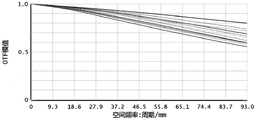
图5所示为本申请一种光学投影系统中实施例1的调制传递函数示意图;FIG. 5 is a schematic diagram of the modulation transfer function of Embodiment 1 in an optical projection system of the present application;
图6所示为本申请一种光学投影系统中实施例2的调制传递函数示意图。FIG. 6 is a schematic diagram of a modulation transfer function of
附图标记说明:Explanation of reference signs:
1、第一透镜;2、第二透镜;3、第三透镜;4、第四透镜;5、第五透镜;6、第六透镜;7、第七透镜;8、光阑;9、等效棱镜;10、保护玻璃;11、显示芯片。1. First lens; 2. Second lens; 3. Third lens; 4. Fourth lens; 5. Fifth lens; 6. Sixth lens; 7. Seventh lens; 8. Aperture; 9. etc. Effect prism; 10. Protective glass; 11. Display chip.
具体实施方式Detailed ways
现在将参照附图来详细描述本申请的各种示例性实施例。应注意到:除非另外具体说明,否则在这些实施例中阐述的部件和步骤的相对布置、数字表达式和数值不限制本申请的范围。Various exemplary embodiments of the present application will now be described in detail with reference to the accompanying drawings. It should be noted that the relative arrangements of components and steps, numerical expressions and numerical values set forth in these embodiments do not limit the scope of the present application unless specifically stated otherwise.
以下对至少一个示例性实施例的描述实际上仅仅是说明性的,决不作为对本申请及其应用或使用的任何限制。The following description of at least one exemplary embodiment is merely illustrative in nature and in no way serves as any limitation of the application, its application or uses.
对于相关领域普通技术人员已知的技术、方法和设备可能不作详细讨论,但在适当情况下,所述技术、方法和设备应当被视为说明书的一部分。Techniques, methods and devices known to those of ordinary skill in the relevant art may not be discussed in detail, but where appropriate, such techniques, methods and devices should be considered part of the description.
在这里示出和讨论的所有例子中,任何具体值应被解释为仅仅是示例性的,而不是作为限制。因此,示例性实施例的其它例子可以具有不同的值。In all examples shown and discussed herein, any specific values should be construed as exemplary only, and not as limitations. Therefore, other instances of the exemplary embodiment may have different values.
应注意到:相似的标号和字母在下面的附图中表示类似项,因此,一旦某一项在一个附图中被定义,则在随后的附图中不需要对其进行进一步讨论。It should be noted that like numerals and letters denote like items in the following figures, therefore, once an item is defined in one figure, it does not require further discussion in subsequent figures.
参照图1-图4所示,根据本申请的一个实施例,提供了一种光学投影系统,所述光学投影系统从放大侧至缩小侧依次包括第一透镜1、光阑8及透镜组;所述透镜组包括至少三个透镜;所述透镜组中最靠近所述光阑8的透镜的光焦度与所述第一透镜1的光焦度相反,且所述透镜组的光焦度为正;所述光学投影系统的总长度TL与所有透镜中最大的一个透镜的口径D之间的比值满足1<TL/D<2.3。Referring to FIGS. 1-4 , according to an embodiment of the present application, an optical projection system is provided, and the optical projection system includes a first lens 1, a
本申请实施例提供的光学投影系统还包括等效棱镜9、保护玻璃10及显示芯片11;进一步具体地,等效棱镜9为等效转折棱镜,等效棱镜9用于将显示芯片11所发出的光线或者所反射出的光线传递到镜头中;保护玻璃10用于保护显示芯片1免受外界污染物的影响;显示芯片11可以为数字微镜器件显示面板(DMD)、硅基液晶显示面板(LCOS)、液晶显示面板(LCD)等。可以理解为,所述显示芯片11为不同波长的激光光源或其他能发出光束的光源体。The optical projection system provided by the embodiment of the present application also includes an
本申请实施例提供的光学投影系统应用于投影装置;该光学投影系统沿光线传输方向包括缩小侧和放大侧,光学投影系统中的显示芯片11、保护玻璃10、等效棱镜9、透镜组、光阑8及第一透镜1沿同一光轴依次设于缩小侧和放大侧之间。其中,缩小侧为投影过程中,生成投影光线的图像源(例如显示芯片11)所在的一侧,也即像方;放大侧为投影过程中,用于显示投影图像的投影面(比如投影屏幕)所在的一侧,也即物方。投影光线的传输方向为由缩小侧至放大侧。但是在实际设计光学投影系统时,根据光路可逆原理,从实际的放大侧至缩小侧对光线进行模拟。The optical projection system provided by the embodiment of the present application is applied to a projection device; the optical projection system includes a reduction side and an enlargement side along the light transmission direction, and the
具体地,在实际的投影过程中,投影光线由显示芯片11发出,自缩小侧朝向放大侧发射,依次经过保护玻璃10、等效棱镜9、透镜组、光阑8及第一透镜1,从而显示出投影图像。Specifically, in the actual projection process, the projection light is emitted by the
本申请实施例中,作为图像源的显示芯片11可选用数字微镜元件(DigitalMicromirror Device,DMD)芯片。DMD是由许多矩阵排列的数字微反射镜组成,工作时每个微反射镜都能够朝正反两个方向进行偏转并锁定,从而使光线按既定的方向进行投射,并且以数万赫兹的频率进行摆动,将来自照明光源的光束通过微反射镜的翻转反射进入光学系统成像在屏幕上。DMD具有分辨率高,信号无需数模转换等优点。本申请实施例采用0.16’DMD,其尺寸横纵比为16:9,具体尺寸例如可以为3.456*1.944mm,配合设计最小投射比为1.2,最大偏置为100%。应注意,本申请实施例中的成像光路架构适用的像源大小不仅局限于0.16’DMD、100%偏置,本申请实施例所允许的全像源大小可在5.2mm以内,全视场角在64°以内。当然,作为图像源的显示芯片11也可以选用硅上液晶(LiquidCrystal OnSilicon,LCOS)芯片、液晶显示面板(Liquid Crystal Display,LCD)或其他可用于出射光线的显示元件,本申请对此不作限制。In the embodiment of the present application, a digital micromirror device (Digital Micromirror Device, DMD) chip may be used as the
在该实施例中,在光阑8的两侧分别设置有透镜,所述的两侧中的一侧即靠近放大侧、另一侧即靠近缩小侧。其中,光阑8的靠近放大侧只设置有一个透镜,即第一透镜1;而光阑8的靠近缩小侧设置有包含至少三个透镜的透镜组,其中,该透镜组中最靠近光阑8的透镜的光焦度与第一透镜1的光焦度相反,并且该透镜组的光焦度为正。例如,在第一透镜1的光焦度为正的情况下,透镜组中最靠近光阑8的透镜的光焦度则为负;例如,在第一透镜1的光焦度为负的情况下,透镜组中最靠近光阑8的透镜的光焦度则为正。在本申请实施例的光学投影系统中,采用反远距型光组方案,光焦度分配遵循负-正分配方式,整个光学投影系统的光焦度平衡,达到投影系统对像值的要求。并且,有助于达到低畸变、图像高分辨率的成像质量。In this embodiment, lenses are provided on both sides of the
此外,在本申请实施例提供的光学投影系统中,通过将该光学投影系统的总长度TL与所有透镜中最大的一个透镜的口径D之间的比值设置为满足1<TL/D<2.3,这样可以在确保成像画面质量的同时,使得光学投影系统的结构紧凑,从而在一定程度上保证光学投影系统的体积尺寸小,使光学投影系统便于携带和使用。亦即,在本申请实施例提供的光学投影系统中,可以在缩小光学投影系统体积的情况下,提升光学投影系统的成像效果。本申请实施例提供的光学投影系统,其投射图像畸变小、相对照度高并且MTF调制函数高。In addition, in the optical projection system provided in the embodiment of the present application, by setting the ratio between the total length TL of the optical projection system and the diameter D of the largest lens among all the lenses to satisfy 1<TL/D<2.3, In this way, the structure of the optical projection system can be made compact while ensuring the quality of the imaging picture, thereby ensuring the small size of the optical projection system to a certain extent, and making the optical projection system easy to carry and use. That is, in the optical projection system provided in the embodiment of the present application, the imaging effect of the optical projection system can be improved while reducing the volume of the optical projection system. The optical projection system provided by the embodiment of the present application has small distortion of the projected image, high relative illuminance and high MTF modulation function.
在一个实施例中,所述光学投影系统满足5.80mm<effl<6.60mm,其中,effl为所述光学投影系统的有效焦距。In one embodiment, the optical projection system satisfies 5.80mm<effl<6.60mm, where effl is the effective focal length of the optical projection system.
在该具体的例子中,通过将光学投影系统的有效焦距effl的值设置为5.80mm<effl<6.60mm,可以在确保成像画面质量的同时,使得光学投影系统的结构紧凑,从而在一定程度上保证光学投影系统的体积尺寸小,使光学投影系统便于携带和使用。In this specific example, by setting the value of the effective focal length effl of the optical projection system to 5.80mm<effl<6.60mm, the structure of the optical projection system can be made compact while ensuring the quality of the imaging picture, thus to a certain extent The size of the optical projection system is ensured to be small, so that the optical projection system is easy to carry and use.
参照图1所示,在一个实施例中,所述透镜组包括从放大侧至缩小侧依次设置的第二透镜2、第三透镜3、第四透镜4及第五透镜5;所述第一透镜1的光焦度为负,所述第二透镜2的光焦度为正。Referring to Fig. 1, in one embodiment, the lens group includes a
在该具体的例子中,该光学投影系统采用5片球面镜,从放大侧至缩小侧依次排布为第一透镜1、第二透镜2、第三透镜3、第四透镜4及第五透镜5。其中,第一透镜1位于光阑8的靠近放大侧,第一透镜1的光焦度为负;第二透镜2、第三透镜3、第四透镜4及第五透镜5位于光阑8的靠近缩小侧,并且,第二透镜2、第三透镜3、第四透镜4及第五透镜5中最靠近光阑8的为第二透镜2,第二透镜2的光焦度为正;且由第二透镜2、第三透镜3、第四透镜4及第五透镜5组成的透镜组的光焦度为正。该实施例中的透镜排布设计在保证光学投影系统的体积尺寸较小的同时保证了较低的成本。In this specific example, the optical projection system adopts five spherical mirrors, which are arranged sequentially from the enlargement side to the reduction side as the first lens 1, the
在一个实施例中,所述第一透镜1的放大侧面为凸面、缩小侧面为凹面;所述第二透镜2的放大侧面为凸面;所述第三透镜3的放大侧面为凹面、缩小侧面为凹面;所述第四透镜4的放大侧面为凹面、缩小侧面为凸面;所述第五透镜5的放大侧面为凸面、缩小侧面为凸面。In one embodiment, the enlarged side of the first lens 1 is convex, and the reduced side is concave; the enlarged side of the
在该具体的例子中,第一透镜1为凸凹透镜,第二透镜2的放大侧面为凸面,第三透镜3为双凹透镜,第四透镜4为凸凹透镜,第五透镜5为双凸透镜。通过对第一透镜1、第二透镜2、第三透镜3、第四透镜4及第五透镜5的以上面型结构设计,使整个光学投影系统达到较高的像值要求以及光线汇聚能力。In this specific example, the first lens 1 is a convex-concave lens, the magnified side of the
在一个实施例中,所述第一透镜1的有效焦距f1满足-9.48mm<f1<-9.08mm;所述第二透镜2的有效焦距f2满足4.137mm<f2<4.637mm;所述第三透镜3的有效焦距f3满足-2.838mm<f3<-2.22mm;所述第四透镜4的有效焦距f4满足6.26mm<f4<6.8mm,所述第五透镜5的有效焦距f5满足6.16mm<f5<6.6mm。并且,所述第一透镜1到所述光阑8的距离与所述第二透镜2到所述光阑8的距离的比值范围为1~3。In one embodiment, the effective focal length f1 of the first lens 1 satisfies -9.48mm<f1<-9.08mm; the effective focal length f2 of the
在该具体的例子中,通过对第一透镜1的有效焦距f1、第二透镜2的有效焦距f2、第三透镜3的有效焦距f3、第四透镜4的有效焦距f4以及第五透镜5的有效焦距f5进行限定;以及通过对第一透镜1到光阑8的距离与第二透镜2到光阑8的距离的比值范围进行限定;能够优化光学设计指标,在满足成像质量的同时,有效减小该光学投影系统的径向尺寸,有利于该光学投影系统的轻薄化以及小型化设计。In this specific example, the effective focal length f1 of the first lens 1, the effective focal length f2 of the
参照图2所示,在一个实施例中,所述透镜组包括从放大侧至缩小侧依次设置的第二透镜2、第三透镜3及第六透镜6,所述第六透镜6为非球面透镜;所述第二透镜2与所述第三透镜3之间具有空气间隔;所述第一透镜1的光焦度为负,所述第二透镜2的光焦度为正。Referring to Fig. 2, in one embodiment, the lens group includes a
在该具体的例子中,相比上一个实施例,采用一个非球面透镜,即第六透镜6取代最为靠近等效棱镜9的两片球面透镜。由于非球面透镜具有较高的校正相差的能力,因此其能够以一代二,从而进一步缩小光学投影系统的体积。进一步地,所述第六透镜6的放大侧面为凸面、缩小侧面为凸面。In this specific example, compared with the previous embodiment, an aspheric lens, that is, the
参照图3所示,在一个实施例中,所述透镜组包括从放大侧至缩小侧依次设置的第三透镜3、第四透镜4、第五透镜5及第七透镜7;所述第一透镜1的光焦度为正,所述第三透镜3的光焦度为负。Referring to Fig. 3, in one embodiment, the lens group includes a
在该具体的例子中,该光学投影系统采用5片球面镜,从放大侧至缩小侧依次排布为第一透镜1、第三透镜3、第四透镜4、第五透镜5及第七透镜7。其中,第一透镜1位于光阑8的靠近放大侧,第一透镜1的光焦度为正;第三透镜3、第四透镜4、第五透镜5及第七透镜7位于光阑8的靠近缩小侧,并且,第三透镜3、第四透镜4、第五透镜5及第七透镜7中最靠近光阑8的为第三透镜3,第三透镜3的光焦度为负;且由第三透镜3、第四透镜4、第五透镜5及第七透镜7组成的透镜组的光焦度为正。该实施例中的透镜排布设计在保证光学投影系统的体积尺寸较小的同时保证了较低的成本。In this specific example, the optical projection system adopts five spherical mirrors, which are arranged sequentially from the enlargement side to the reduction side as the first lens 1, the
在一个实施例中,所述第一透镜1的放大侧面为凸面、缩小侧面为凸面;所述第三透镜3的放大侧面为凹面、缩小侧面为凹面;所述第四透镜4的放大侧面为凹面、缩小侧面为凸面;所述第五透镜5的放大侧面为凸面、缩小侧面为凸面;所述第七透镜7的放大侧面为凸面。In one embodiment, the enlarged side of the first lens 1 is convex, and the reduced side is convex; the enlarged side of the
在该具体的例子中,第一透镜1为双凸透镜,第三透镜3为双凹透镜,第四透镜4为凸凹透镜,第五透镜5为双凸透镜;所述第七透镜7的放大侧面为凸面。通过对第一透镜1、第三透镜3、第四透镜4、第五透镜5及第七透镜7的以上面型结构设计,使整个光学投影系统达到较高的像值要求以及光线汇聚能力。In this specific example, the first lens 1 is a biconvex lens, the
在一个实施例中,所述第一透镜1的有效焦距f1满足9.48mm<f1<9.08mm;所述第三透镜3的有效焦距f3满足-2.838mm<f3<-2.22mm;所述第四透镜4的有效焦距f4满足6.26mm<f4<6.8mm,所述第五透镜5的有效焦距f5满足6.16mm<f5<6.6mm所述第七透镜7的有效焦距f7满足6.7mm<f7<8.6mm。In one embodiment, the effective focal length f1 of the first lens 1 satisfies 9.48mm<f1<9.08mm; the effective focal length f3 of the
在该具体的例子中,通过对第一透镜1的有效焦距f1、第三透镜3的有效焦距f3、第四透镜4的有效焦距f4、第五透镜5的有效焦距f5以及第七透镜7的有效焦距f7进行限定;能够优化光学设计指标,在满足成像质量的同时,有效减小该光学投影系统的径向尺寸,有利于该光学投影系统的轻薄化以及小型化设计。In this specific example, the effective focal length f1 of the first lens 1, the effective focal length f3 of the
参照图4所示,在一个实施例中,所述透镜组包括从放大侧至缩小侧依次设置的第三透镜3、第四透镜4及第六透镜6,所述第六透镜6为非球面透镜;所述第一透镜1的光焦度为正,所述第三透镜3的光焦度为负。Referring to Fig. 4, in one embodiment, the lens group includes a
在该具体的例子中,相比上一个实施例,采用一个非球面透镜,即第六透镜6取代最为靠近等效棱镜9的两片球面透镜。由于非球面透镜具有较高的校正相差的能力,因此其能够以一代二,从而进一步缩小光学投影系统的体积。进一步地,所述第六透镜6的放大侧面为凸面、缩小侧面为凸面。In this specific example, compared with the previous embodiment, an aspheric lens, that is, the
本申请实施例提供的光学投影系统,其投射图像畸变小、相对照度高并且MTF调制函数高;通过以上各参数的优化配置,其可以在各个视场下达到图像清晰度较高的成像效果。The optical projection system provided by the embodiment of the present application has small distortion of the projected image, high relative illuminance and high MTF modulation function; through the optimal configuration of the above parameters, it can achieve high image definition imaging effect in each field of view.
根据本申请的另一个实施例,提供了一种投影装置,所述投影装置包括如上所述的光学投影系统。所述投影装置例如可以为投影装置。投影装置例如可以是投影机、或者照明光机等。According to another embodiment of the present application, a projection device is provided, and the projection device includes the above-mentioned optical projection system. The projection device may be, for example, a projection device. The projection device may be, for example, a projector, or an illuminating machine or the like.
实施例1:Example 1:
参照图1所示,从放大侧至缩小侧,该光学投影系统依次设置有第一透镜1、光阑8、第二透镜2、第三透镜3、第四透镜4、第五透镜5、等效棱镜9、保护玻璃10及显示芯片11;该光学投影系统满足有效焦距effl=6.39mm,光学投影系统的光学总长TL为8.7mm。023’DMD设计目标如下:Referring to Fig. 1, from the enlargement side to the reduction side, the optical projection system is provided with a first lens 1, a
投射比为1.85,投影距离为609mm,偏置0%,TV畸变<0.5%,全视场MTF>0.5@96lp/mm,远心度<1.5°,色差<0.5pixel,F#1.71。Throw ratio is 1.85, projection distance is 609mm, offset 0%, TV distortion <0.5%, full field of view MTF>0.5@96lp/mm, telecentricity <1.5°, chromatic aberration <0.5pixel, F#1.71.
该实施例中的光学投影系统包含5片球面透镜;其中,第一透镜1的放大侧面S1为凸面、缩小侧面S2为凹面;所述第二透镜2的放大侧面S3为凸面、缩小侧面S4为凸面;所述第三透镜3的放大侧面S5为凹面、缩小侧面S6为凹面;所述第四透镜4的放大侧面S7为凹面、缩小侧面S8为凸面;所述第五透镜5的放大侧面S9为凸面、缩小侧面S10为凸面。The optical projection system in this embodiment comprises 5 spherical lenses; wherein, the enlargement side S1 of the first lens 1 is a convex surface, and the reduction side S2 is a concave surface; the enlargement side S3 of the
实施例1中涉及的各个参数如下表1所示:Each parameter involved in embodiment 1 is shown in table 1 below:
表1Table 1

实施例1中所示的光学投影系统的调制传递函数示意图如图5所示,由图示可见,各视场的MTF值均高于0.56,可见在各个视场下经该系统成像后的图像清晰度非常高,其他性能也均满足设计要求。The schematic diagram of the modulation transfer function of the optical projection system shown in Example 1 is shown in Figure 5. It can be seen from the diagram that the MTF values of each field of view are higher than 0.56, and it can be seen that the image formed by the system under each field of view The definition is very high, and other performances also meet the design requirements.
实施例2:Example 2:
参照图4所示,从放大侧至缩小侧,该光学投影系统依次设置有第一透镜1、光阑8、第三透镜3、第四透镜4、第六透镜6、等效棱镜9、保护玻璃10及显示芯片11;该光学投影系统满足有效焦距effl=6.45mm,光学投影系统的光学总长TL为8.6mm。023’DMD设计目标如下:Referring to Fig. 4, from the enlargement side to the reduction side, the optical projection system is provided with a first lens 1, a
投射比为1.85,投影距离为609mm,偏置0%,TV畸变<0.5%,全视场MTF>0.5@96lp/mm,远心度<1.5°,色差<0.5pixel,F#1.71。Throw ratio is 1.85, projection distance is 609mm, offset 0%, TV distortion <0.5%, full field of view MTF>0.5@96lp/mm, telecentricity <1.5°, chromatic aberration <0.5pixel, F#1.71.
该实施例中的光学投影系统包含3片球面透镜和1片非球面透镜;其中,第一透镜1的放大侧面S1为凸面、缩小侧面S2为凸面;所述第三透镜3的放大侧面S3为凹面、缩小侧面S4为凹面;所述第四透镜4的放大侧面S5为凹面、缩小侧面S6为凸面;所述所述第六透镜6的放大侧面S7为凸面、缩小侧面S8为凸面。The optical projection system in this embodiment includes 3 spherical lenses and 1 aspheric lens; wherein, the enlarged side S1 of the first lens 1 is a convex surface, and the reduced side S2 is a convex surface; the enlarged side S3 of the
实施例2中涉及的各个参数如下表2所示:Each parameter involved in

实施例2中所示的光学投影系统的调制传递函数示意图如图6所示,由图示可见,各视场的MTF值均高于0.55,可见在各个视场下经该系统成像后的图像清晰度非常高,其他性能也均满足设计要求。The schematic diagram of the modulation transfer function of the optical projection system shown in Example 2 is shown in Figure 6. It can be seen from the diagram that the MTF values of each field of view are higher than 0.55, and it can be seen that the images imaged by the system under each field of view The definition is very high, and other performances also meet the design requirements.
虽然已经通过例子对本申请的一些特定实施例进行了详细说明,但是本领域的技术人员应该理解,以上例子仅是为了进行说明,而不是为了限制本申请的范围。本领域的技术人员应该理解,可在不脱离本申请的范围和精神的情况下,对以上实施例进行修改。本申请的范围由所附权利要求来限定。Although some specific embodiments of the present application have been described in detail through examples, those skilled in the art should understand that the above examples are only for illustration, rather than limiting the scope of the present application. Those skilled in the art will appreciate that modifications can be made to the above embodiments without departing from the scope and spirit of the application. The scope of the application is defined by the appended claims.
Claims (12)
Priority Applications (1)
| Application Number | Priority Date | Filing Date | Title |
|---|---|---|---|
| CN202210918444.8A CN115356837B (en) | 2022-08-01 | 2022-08-01 | Optical projection system and projection device |
Applications Claiming Priority (1)
| Application Number | Priority Date | Filing Date | Title |
|---|---|---|---|
| CN202210918444.8A CN115356837B (en) | 2022-08-01 | 2022-08-01 | Optical projection system and projection device |
Publications (2)
| Publication Number | Publication Date |
|---|---|
| CN115356837A true CN115356837A (en) | 2022-11-18 |
| CN115356837B CN115356837B (en) | 2025-10-28 |
Family
ID=84031440
Family Applications (1)
| Application Number | Title | Priority Date | Filing Date |
|---|---|---|---|
| CN202210918444.8A Active CN115356837B (en) | 2022-08-01 | 2022-08-01 | Optical projection system and projection device |
Country Status (1)
| Country | Link |
|---|---|
| CN (1) | CN115356837B (en) |
Cited By (2)
| Publication number | Priority date | Publication date | Assignee | Title |
|---|---|---|---|---|
| CN115616743A (en) * | 2022-12-02 | 2023-01-17 | 歌尔光学科技有限公司 | A kind of optical projection system and electronic equipment |
| WO2025148579A1 (en) * | 2024-01-10 | 2025-07-17 | 极米科技股份有限公司 | Projection lens |
Citations (8)
| Publication number | Priority date | Publication date | Assignee | Title |
|---|---|---|---|---|
| JP2008020893A (en) * | 2006-06-15 | 2008-01-31 | Fujinon Corp | Imaging lens |
| US20160212353A1 (en) * | 2015-01-21 | 2016-07-21 | Ability Opto-Electronics Technology Co., Ltd. | Optical Image Capturing System |
| TWM579728U (en) * | 2019-01-07 | 2019-06-21 | 先進光電科技股份有限公司 | Mobile carrier auxiliary system and vehicle electronic rear-view mirror |
| CN110412724A (en) * | 2018-04-28 | 2019-11-05 | 宁波舜宇车载光学技术有限公司 | optical lens |
| CN111766678A (en) * | 2019-04-01 | 2020-10-13 | 宁波舜宇车载光学技术有限公司 | Optical lens and imaging apparatus |
| CN112526709A (en) * | 2019-08-30 | 2021-03-19 | 三星电机株式会社 | Optical imaging system, camera module and portable electronic device |
| WO2021135606A1 (en) * | 2019-12-31 | 2021-07-08 | 广景视睿科技(深圳)有限公司 | Projection lens |
| CN114047613A (en) * | 2021-10-29 | 2022-02-15 | 歌尔光学科技有限公司 | Optical system and projection device |
-
2022
- 2022-08-01 CN CN202210918444.8A patent/CN115356837B/en active Active
Patent Citations (8)
| Publication number | Priority date | Publication date | Assignee | Title |
|---|---|---|---|---|
| JP2008020893A (en) * | 2006-06-15 | 2008-01-31 | Fujinon Corp | Imaging lens |
| US20160212353A1 (en) * | 2015-01-21 | 2016-07-21 | Ability Opto-Electronics Technology Co., Ltd. | Optical Image Capturing System |
| CN110412724A (en) * | 2018-04-28 | 2019-11-05 | 宁波舜宇车载光学技术有限公司 | optical lens |
| TWM579728U (en) * | 2019-01-07 | 2019-06-21 | 先進光電科技股份有限公司 | Mobile carrier auxiliary system and vehicle electronic rear-view mirror |
| CN111766678A (en) * | 2019-04-01 | 2020-10-13 | 宁波舜宇车载光学技术有限公司 | Optical lens and imaging apparatus |
| CN112526709A (en) * | 2019-08-30 | 2021-03-19 | 三星电机株式会社 | Optical imaging system, camera module and portable electronic device |
| WO2021135606A1 (en) * | 2019-12-31 | 2021-07-08 | 广景视睿科技(深圳)有限公司 | Projection lens |
| CN114047613A (en) * | 2021-10-29 | 2022-02-15 | 歌尔光学科技有限公司 | Optical system and projection device |
Cited By (3)
| Publication number | Priority date | Publication date | Assignee | Title |
|---|---|---|---|---|
| CN115616743A (en) * | 2022-12-02 | 2023-01-17 | 歌尔光学科技有限公司 | A kind of optical projection system and electronic equipment |
| CN115616743B (en) * | 2022-12-02 | 2023-04-18 | 歌尔光学科技有限公司 | Optical projection system and electronic equipment |
| WO2025148579A1 (en) * | 2024-01-10 | 2025-07-17 | 极米科技股份有限公司 | Projection lens |
Also Published As
| Publication number | Publication date |
|---|---|
| CN115356837B (en) | 2025-10-28 |
Similar Documents
| Publication | Publication Date | Title |
|---|---|---|
| CN115047591B (en) | Projection lens and projection device | |
| CN105652421B (en) | A kind of camera lens for digital projector | |
| CN114047613B (en) | Optical system and projection device | |
| CN114942561B (en) | A kind of optical projection system and electronic equipment | |
| CN101387736B (en) | Projecting lens | |
| WO2021031499A1 (en) | Projection lens | |
| CN108267834A (en) | fixed focus lens | |
| CN114859559A (en) | Optical lens | |
| TWI795592B (en) | Projection lens and projector | |
| CN109491053B (en) | Miniature projection lens | |
| WO2023184752A1 (en) | Optical projection system and electronic device | |
| TWM592984U (en) | Projection lens and projection apparatus | |
| CN115356837B (en) | Optical projection system and projection device | |
| CN109298584B (en) | Projection lens and projector | |
| CN110879457B (en) | Projection optical system and projection apparatus | |
| CN114924380B (en) | Optical projection system and electronic equipment | |
| CN114594574B (en) | An optical projection system and electronic device | |
| CN115453716B (en) | Optical projection system and projection device | |
| CN114690377B (en) | Optical projection system and electronic equipment | |
| CN114706192B (en) | Optical projection system and electronic equipment | |
| CN116125637B (en) | Projection lens and projection device | |
| TWI809587B (en) | Projection lens | |
| WO2016125681A1 (en) | Projection optical system and projection device | |
| CN117572597A (en) | Projection lens and projection device | |
| CN116300020A (en) | Zoom objective system for miniature projection |
Legal Events
| Date | Code | Title | Description |
|---|---|---|---|
| PB01 | Publication | ||
| PB01 | Publication | ||
| SE01 | Entry into force of request for substantive examination | ||
| SE01 | Entry into force of request for substantive examination | ||
| GR01 | Patent grant | ||
| GR01 | Patent grant |