Disclosure of Invention
In view of the above, it is necessary to provide an array scanning holographic penetration imaging method and a handheld holographic penetration imaging radar system capable of solving the above problems.
A method of array scanning holographic transfixing imaging, the method comprising:
acquiring detection data, wherein the detection data are echo data obtained by carrying out continuous and multiple rapid scanning while a radar probe with a multi-transmitting and multi-receiving array antenna moves in a region to be detected on the surface of a medium;
acquiring positioning data, wherein the positioning data are a plurality of position images for recording position changes of a radar probe when the radar probe performs multiple rapid scans in the area to be detected, and each position image corresponds to the position change of the radar probe during one rapid scan;
processing the positioning data to obtain the position coordinates of the radar probe in the area to be detected during each rapid scanning;
and processing according to the position coordinates of the radar probe during each quick scanning and the corresponding detection data to obtain the imaging result of the target under the surface layer of the area to be detected.
In one embodiment, when the radar probe of the multiple-input multiple-output array antenna performs fast scanning, one antenna is a transmitting antenna, the other antennas are receiving antennas, the other antenna is switched to be a transmitting antenna, the other antennas are receiving antennas, and the fast scanning is performed after all the antennas are traversed by analogy.
In one embodiment, the handheld radar probe reciprocates on the surface of the medium when performing quick scanning until the moving track covers the whole area to be detected.
In one embodiment, the processing the positioning data to obtain the position coordinates of the radar probe in the region to be detected during each fast scan includes:
calibration code elements are arranged on the boundary of a region to be detected on the surface of the medium, the number of the calibration code elements is three, the calibration code elements are respectively arranged at the upper left corner, the lower left corner and the upper right corner of the boundary of the region to be detected, the actual position coordinates of each calibration code element are obtained, and a positioning code element is also arranged on one side, back to the surface of the medium, of the radar probe;
carrying out contour detection and feature extraction on each position image, and identifying each calibration code element and the pixel coordinate of the center point of the positioning code element;
constructing a coordinate transformation matrix according to the pixel coordinates and the actual position coordinates of each calibration code element in each position image;
and converting the pixel coordinates of the central point of the positioning code element in each position image into position coordinates according to the coordinate transformation matrix, wherein the position coordinates are actual position coordinates in the area to be detected when the radar probe performs quick scanning each time.
In one embodiment, the processing according to the position coordinate of the radar probe during each fast scanning and the corresponding detection data to obtain the imaging result of the subsurface target of the region to be detected includes:
constructing an imaging space according to the region to be detected and a preset imaging depth;
calculating according to the imaging space and the position coordinates of the radar probe during each quick scanning to obtain a compensation phase;
and performing point-by-point compensation phase accumulation summation according to the detection data to obtain the imaging result.
A handheld holographic penetration imaging radar system, the system comprising: the system comprises a handheld radar probe, a visual positioning unit, an imaging processing unit and a scanning control unit;
the scanning control unit respectively sends detection instructions to the handheld radar probe and the visual positioning unit;
the handheld radar probe is a multi-transmitting multi-receiving antenna array radar, and is used for carrying out continuous and multi-time rapid scanning while moving in a to-be-detected area on the surface of a medium according to the detection instruction to obtain echo data and sending the echo data serving as detection data to the scanning control unit;
the visual positioning unit records a plurality of position images of the radar probe during multiple rapid scanning in the area to be detected according to the detection instruction, each position image corresponds to the position change of the radar probe during one rapid scanning, and the position images are used as positioning data to be sent to the scanning control unit;
the scanning control unit sends the received detection data and the positioning data to the imaging processing unit;
the imaging processing unit processes the detection data and the positioning data according to the array scanning holographic penetration imaging method to obtain an imaging result of the target under the surface layer of the area to be detected, and sends the imaging result to the scanning control unit;
the scanning control unit receives and displays the imaging result.
In one embodiment, the handheld radar probe is an integrated radar, and comprises a microcontroller, a multi-channel radio frequency transceiver chip, a radio frequency switch, a communication element and a plurality of antennas, wherein the plurality of antennas are integrated on a planar board to form an antenna array.
In one embodiment, the visual positioning unit comprises a camera device, three scaling code elements and a positioning code element;
the camera lens of the camera device is over against the area to be detected, and the camera shooting range of the camera device comprises all the area to be detected;
the three calibration code elements are respectively arranged at the upper left corner, the lower left corner and the upper right corner of the boundary of the area to be detected;
the positioning code element is arranged on one side, back to the medium surface, of the radar probe.
In one embodiment, the calibration code element and the positioning code element adopt optical mark patterns including annular code marks, cross code marks and two-dimensional code marks.
In one embodiment, the scan control unit is an upper computer.
A holographic transfixion imaging apparatus, said apparatus comprising:
the detection data acquisition module is used for acquiring detection data, wherein the detection data are echo data obtained by performing continuous and multiple rapid scanning while a radar probe with a multi-transmitting and multi-receiving array antenna moves in a region to be detected on the surface of a medium;
the positioning data acquisition module is used for acquiring positioning data, the positioning data are a plurality of position images for recording position changes of the radar probe when the radar probe performs multiple rapid scans in the area to be detected, and each position image corresponds to the position change of the radar probe during one rapid scan;
the position coordinate obtaining module is used for processing the positioning data to obtain the position coordinate of the radar probe in the area to be detected during each quick scanning;
and the imaging result obtaining module is used for processing according to the position coordinates of the radar probe in each quick scanning and the corresponding detection data to obtain the imaging result of the target under the surface layer of the area to be detected.
A computer device comprising a memory and a processor, the memory storing a computer program, the processor implementing the following steps when executing the computer program:
acquiring detection data, wherein the detection data are echo data obtained by carrying out continuous and multiple rapid scanning while a radar probe with a multi-transmitting and multi-receiving array antenna moves in a region to be detected on the surface of a medium;
acquiring positioning data, wherein the positioning data are a plurality of position images for recording position changes of a radar probe when the radar probe performs multiple rapid scans in the area to be detected, and each position image corresponds to the position change of the radar probe during one rapid scan;
processing the positioning data to obtain the position coordinates of the radar probe in the area to be detected during each rapid scanning;
and processing according to the position coordinates of the radar probe during each quick scanning and the corresponding detection data to obtain the imaging result of the target under the surface layer of the area to be detected.
A computer-readable storage medium, on which a computer program is stored which, when executed by a processor, carries out the steps of:
acquiring detection data, wherein the detection data are echo data obtained by carrying out continuous and multiple rapid scanning while a radar probe with a multi-transmitting and multi-receiving array antenna moves in a region to be detected on the surface of a medium;
acquiring positioning data, wherein the positioning data are a plurality of position images for recording position changes of a radar probe when the radar probe performs multiple rapid scans in the area to be detected, and each position image corresponds to the position change of the radar probe during one rapid scan;
processing the positioning data to obtain a position coordinate of the radar probe in the area to be detected during each quick scanning;
and processing according to the position coordinates of the radar probe during each quick scanning and the corresponding detection data to obtain the imaging result of the target under the surface layer of the area to be detected.
According to the array scanning holographic penetration imaging method and the handheld holographic penetration imaging radar system, echo data are obtained by continuously and rapidly scanning multiple times while the multiple-shot array radar probe moves in a to-be-detected area on the surface of a medium, position transformation of the radar probe during movement is recorded by using an image while the radar probe scans, position coordinates of the radar probe during scanning are obtained by subsequently processing a position image, and an imaging result of a target under the surface layer of the to-be-detected area is finally obtained by calculating according to the position coordinates and the echo data.
Detailed Description
In order to make the objects, technical solutions and advantages of the present application more clearly understood, the present application is further described in detail below with reference to the accompanying drawings and embodiments. It should be understood that the specific embodiments described herein are merely illustrative of and not restrictive on the broad application.
As shown in fig. 1, there is provided an array scanning holographic penetration imaging method, comprising the steps of:
step S100, acquiring detection data, wherein the detection data are echo data obtained by continuously and rapidly scanning multiple times while a multi-transmitting and multi-receiving array radar probe moves in a region to be detected on the surface of a medium;
step S110, acquiring positioning data, wherein the positioning data are a plurality of position images for recording position changes of the radar probe during a plurality of times of fast scanning in the area to be detected, and each position image corresponds to the position change of the radar probe during one time of fast scanning;
step S120, processing the positioning data to obtain the position coordinates of the radar probe in the area to be detected when the radar probe performs each quick scanning;
and step S130, processing according to the position coordinates of the radar probe during each quick scanning and the corresponding detection data to obtain the imaging result of the subsurface target of the area to be detected.
In step S100, the radar probe repeatedly moves in the region to be detected on the surface of the medium until the moving route covers the whole detection region with the radar probe, and the radar probe adopts a multi-transmission multi-reception array. When scanning, one antenna in the antenna array is used as a transmitting antenna, the other antennas are used as receiving antennas, then the other antenna is switched to be used as a transmitting antenna, the other antennas are used as receiving antennas, and the like, and when all the antennas are traversed, one-time quick scanning is finished. During the process that the radar probe finishes scanning the whole area to be detected, multiple times of rapid scanning are carried out.
In the embodiment, when the rapid scanning is performed, the radar probe reciprocates on the surface of the medium until the moving track covers the whole area to be detected.
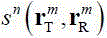
Specifically, after the radar probe scans, the echo data, i.e. the detection data, received by each transceiving channel is corresponding to
Upper label of
nThe number of fast scans is indicated and,
、
respectively expressed in one fast scan
mThe transmitting and receiving antenna positions of the transceiving combination.
In step S110, when the radar probe moves and scans the region to be detected, an image capturing device records the whole process, and a plurality of images record the moving track of the radar probe in the region to be detected. That is to say, each image records a different position of the radar probe in the area to be detected. And each position image corresponds to the position change of the radar probe during one-time quick scanning respectively.
In step S120, calibration code elements are arranged on the boundary of the to-be-detected region on the surface of the medium, the number of the calibration code elements is three, the calibration code elements are respectively arranged at the upper left corner, the lower left corner and the upper right corner of the boundary of the to-be-detected region, the actual position coordinates of each calibration code element are obtained, and a positioning code element is further arranged on one side of the radar probe, which faces away from the surface of the medium.
Further, a coordinate transformation relation is established according to the conversion from the shooting space of the position image to the physical space, and the actual position of each rapid scanning radar probe can be obtained according to the relation; and constructing a coordinate transformation matrix according to the pixel coordinates and the actual position coordinates of each calibration code element in each position image, and converting the pixel coordinates of the central point of the positioning code element in each position image into position coordinates according to the coordinate transformation matrix, wherein the position coordinates are the actual position coordinates in the region to be detected when the radar probe performs quick scanning each time.
Specifically, the pixel coordinates of the centers of three calibration code elements can be obtained by identifying each position image
Wherein 0, 1, 2 respectively represent the scaling code elements arranged at the upper left corner, the lower left corner and the upper right corner of the boundary of the region to be detected, and the subscript pix represents the pixel coordinates in the image. The actual position of the known scaled symbol is
The superscript T represents the matrix transposition operation, and the following relationship is given:
solving from the pixel coordinates and the actual position coordinates of the three calibration symbols
And
further, a coordinate transformation matrix can be obtained
:
And the first place is
nAt sub-fast scanLocating pixel coordinates of a symbol
The physical coordinates are transformed as follows:
in the formula (4), let us note
nThe radar position at the time of the sub-snapshot is
。
In the embodiment, the scanning process of the radar probe is continuous, and a stop-go-stop mode is not needed, so that the detection efficiency is greatly improved compared with the point-by-point measurement in the prior art.
In the embodiment, the calibration code element and the positioning code element adopt optical mark patterns including annular code marks, cross-shaped code marks and two-dimensional code marks.
In this embodiment, the two-dimensional code identifier is used as the scaling symbol and the positioning symbol, and the coordinates of the center pixel of the scaling symbol and the positioning symbol can be detected from the image by the two-dimensional code detection technique.
In one embodiment, the scaling symbol and the positioning symbol are identified by a two-dimensional code, and the coordinates of the center pixel of the scaling symbol and the positioning symbol can be detected from the image by a two-dimensional code detection technology.
In step S130, an algorithm of point-by-point phase compensation coherent superposition imaging processing is adopted, and target imaging is performed by using the actual position coordinates of the radar and the detection data obtained in step S120 for each fast scanning, including: and finally, according to the detection data, carrying out accumulated summation by adopting point-by-point compensation phases to obtain the imaging result.
Specifically, when an imaging space is constructed, a region to be imaged is formedThe region to be detected is divided into grids with the grid interval of
,
And
respectively represent
xDirection and
ythe imaging range of the direction is set,
,
. The preset distance of the depth layer to be imaged is set as
And the coordinates of any point in the imaging space are recorded as
Thus, for a certain imaging point
Calculating the distance from the imaging point to the transmitting antenna and the receiving antenna of each channel
And
:
in the formula (5), the first and second groups,
representing an imaging point
To the first
nSecond in sub-fast scan
mThe distance of the transmit antennas of the group transmit-receive combination,
representing an image point
To the first
nSecond in sub-fast scan
mThe distance of the combined receive antenna is grouped.
Spatial wavenumber of known medium
Wherein
Is the frequency of the electromagnetic wave and,
is the propagation velocity of the electromagnetic wave in the medium, and the compensation phase is calculated by the following formula:
next, the phase accumulation summation is compensated point by point:
in the formula (7), the measurement data corresponding to each transceiving channel is
Upper label of
nThe number of fast scans is indicated and,
、
respectively expressed in a snapshot
mThe transmitting and receiving antenna positions of the transceiving combination.
And finally, after imaging is finished, displaying to obtain a final imaging result in the medium so as to achieve the aim of detection.
As shown in fig. 2, the present application also provides a hand-held holographic penetration imaging radar system matched with the above method, comprising: the system comprises a handheld radar probe 1, a visual positioning unit, an imaging processing unit 2 and a scanning control unit 3;
firstly, a scanning control unit 3 respectively sends detection instructions to the handheld radar probe 1 and the visual positioning unit;
the handheld radar probe 1 moves in a region to be detected on the surface of a medium and simultaneously carries out continuous and multiple times of quick scanning to obtain echo data according to a detection instruction, and sends the echo data serving as detection data to the scanning control unit 3;
when the radar probe 1 is held by hand for scanning, the visual positioning unit records a plurality of position images of the radar probe, which change in position when the radar probe performs multiple times of quick scanning in the area to be detected, according to the detection instruction, wherein each position image corresponds to the position change of the radar probe during one time of quick scanning, and the position images are sent to the scanning control unit 3 as positioning data;
the scanning control unit 3 sends the received detection data and the positioning data to the imaging processing unit 2;
the imaging processing unit 2 processes the detection data and the positioning data according to the array scanning holographic penetration imaging method to obtain an imaging result of the target under the surface layer of the region to be detected, which has been described above, and is not described herein again, and sends the imaging result to the scanning control unit 3;
finally, the scan control unit 3 receives and displays the imaging result.
In this embodiment, the handheld radar probe 1 is a multiple-input multiple-output array integrated radar, and includes a microcontroller, a multi-channel rf transceiver chip, an rf switch, a communication element, and a plurality of antennas, where the plurality of antennas are integrated on a planar board to form an antenna array. And each antenna can be switched to a transmit or receive mode by the microcontroller through the radio frequency switch. When one antenna works in a transmitting mode, the other antennas are in a receiving state, and multiple-transmitting and multiple-receiving detection is realized by time-sharing switching of transmitting and receiving.
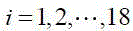
In the present embodiment, the antenna array layout of the multiple-transmit multiple-receive handheld radar probe 1 is shown in fig. 3, and includes 18 transmit-receive antennas, which operate in the C-band. The distance between the antennas is 2cm, and the array range is 6cm × 8cm. The local coordinates of each antenna within the array using the center of the array as the origin are noted
Middle and upper label of the formula
The numbers of the antennas are shown, and the superscript T indicates the matrix transposition operation.
After the radar probe receives a scanning instruction of the scanning control module, the microcontroller firstly transmits the No. 1 antenna and receives the rest antennas to form a receiving-transmitting combination of 1 transmitting and 17 receiving. Then, the No. 2 antenna is switched to be transmitting and the other antennas are used for receiving, and so on, and all the antennas are traversed. And removing repeated receiving and transmitting combinations to obtain 153 receiving and transmitting channel data, recording the channel data as one snapshot, and transmitting the snapshot to the scanning control module through the communication interface. The measured data corresponding to each transceiving channel is
Upper label of
nThe number of times of the snap shots is indicated,
、
respectively expressed in a snapshot
mTransmitting and receiving of a transmitting and receiving combinationAnd receiving the antenna position.
In the present embodiment, the visual localization unit includes an image pickup device 41, three scaling symbols 42, and one localization symbol 43. The imaging lens of the imaging device 41 is treating the region to be detected, and the imaging range thereof includes the entire region to be detected. The three calibration code elements 42 are respectively arranged at the upper left corner, the lower left corner and the upper right corner of the boundary of the area to be detected. And the positioning code element 43 is arranged on the side of the handheld radar probe 1, which is opposite to the surface of the medium, so that the positioning code element 43 moves along with the handheld radar probe 1, and the position coordinates of the handheld radar probe 1 are finally determined by calculating the position coordinates of the positioning code element 43.
In the present embodiment, the calibration symbols 42 and the positioning symbols 43 adopt optical mark patterns, including annular coded marks, cross-shaped coded marks and two-dimensional code marks.
In one embodiment, the scaling symbols 42 and the positioning symbols 43 are identified by two-dimensional codes, and the coordinates of the center pixels of the scaling symbols 42 and the positioning symbols 43 can be detected from the image by a two-dimensional code detection technique.
In the present embodiment, the scan control unit 3 is an upper computer. The imaging processing unit 2 may be a calling program in an upper computer, may also be other computer devices, and may also use a storage medium as a carrier.
When the handheld holographic penetration imaging radar system is used for detecting a region to be detected:
firstly, arranging a calibration code element at the upper left corner, the upper right corner and the lower left corner of the boundary of a region to be detected, as shown in fig. 4, and also showing a target shape prearranged in the board in fig. 4, then arranging a positioning code element on a handheld radar probe, arranging a camera at a position right facing the region to be detected, enabling the camera shooting range of the camera to include the whole region to be detected, and then starting the initialization function of a scanning control unit.
And then, placing the handheld radar probe on the surface of the measured medium, starting a scanning process through a scanning control program, moving the handheld radar probe on the surface of the area to be detected in a motion mode similar to a blackboard erasing mode until the coverage of the scanning area is completed, and monitoring the current scanning process through the scanning control unit and the visual positioning unit in the scanning process.
And finally, after the handheld radar probe finishes scanning the whole detection area, sending detected echo data to a scanning control unit, sending positioning data recorded with the moving process of the radar probe to the scanning control unit by a visual positioning unit, calling an imaging processing unit through the scanning control unit, and processing the received echo data and the positioning data according to the array scanning holographic penetration imaging method to obtain final panoramic data of the target.
In this embodiment, an imaging experiment of a preset target inside a wood board according to the array scanning holographic penetration imaging method and the handheld holographic penetration imaging radar system is also provided. As shown in fig. 5, the moving track of the radar probe during scanning at the global position displayed by the coordinate axis is obtained after the positioning data is processed. As shown in fig. 6, a fused imaging result obtained after the positioning data and the detection data are processed according to the array scanning holographic penetration imaging method, compared with fig. 4, it can be proved that the size, the position, the shape, etc. of the target located inside the medium can be clearly detected according to the array scanning holographic penetration imaging method and the handheld holographic penetration imaging radar system proposed herein, and all the sizes, the positions, the shapes, etc. are consistent with the preset target, which illustrates the effectiveness of the method and the system.
In the array scanning holographic penetration imaging method and the handheld holographic penetration imaging radar system, the detection scanning speed can be greatly improved by the multi-transmitting and multi-receiving radar system, a complex electromechanical scanning device is omitted by a visual positioning scheme, the volume weight of the system is greatly reduced, the limitation of penetration imaging radar scanning on a regular scanning track is eliminated by the array scanning holographic penetration imaging method, and handheld free movement and rapid scanning are realized. Compared with the scheme of directly adopting a large array, the scheme of the system combining the multiple-transmitting and multiple-receiving array radar with the space scanning ensures the detection effect, obviously reduces the system scale and reduces the cost. The method can be applied to wall penetration imaging, detection of hidden objects, nondestructive detection of non-metallic materials and the like.
It should be understood that, although the steps in the flowchart of fig. 1 are shown in order as indicated by the arrows, the steps are not necessarily performed in order as indicated by the arrows. The steps are not limited to being performed in the exact order illustrated and, unless explicitly stated herein, may be performed in other orders. Moreover, at least some of the steps in fig. 1 may include multiple sub-steps or multiple stages that are not necessarily performed at the same time, but may be performed at different times, and the order of performing the sub-steps or stages is not necessarily sequential, but may be performed alternately or alternately with other steps or at least some of the sub-steps or stages of other steps.
In one embodiment, as shown in fig. 7, there is provided a holographic transmission imaging apparatus comprising: a detection data obtaining module 200, a positioning data obtaining module 210, a position coordinate obtaining module 220, and an imaging result obtaining module 230, wherein:
a detection data acquisition module 200, configured to acquire detection data, where the detection data is echo data obtained by performing continuous multiple fast scanning while a radar probe with a multiple-transmit multiple-receive array antenna moves in a region to be detected on a medium surface;
a positioning data obtaining module 210, configured to obtain positioning data, where the positioning data are multiple position images that record position changes of the radar probe during multiple fast scans in the area to be detected, and each position image corresponds to a position change of the radar probe during one fast scan;
a position coordinate obtaining module 220, configured to process the positioning data to obtain a position coordinate of the radar probe in the region to be detected during each fast scanning;
and an imaging result obtaining module 230, configured to process the position coordinates of the radar probe during each fast scanning and the corresponding detection data to obtain an imaging result of the subsurface target of the region to be detected.
The specific definition of the holographic penetrating imaging device can be referred to the definition of the array scanning holographic penetrating imaging method in the above, and the detailed description is omitted here. The various modules in the holographic transmission imaging device can be wholly or partially realized by software, hardware and a combination thereof. The modules can be embedded in a hardware form or independent of a processor in the computer device, and can also be stored in a memory in the computer device in a software form, so that the processor can call and execute operations corresponding to the modules.
In one embodiment, a computer device is provided, which may be a terminal, and its internal structure diagram may be as shown in fig. 8. The computer device includes a processor, a memory, a network interface, a display screen, and an input device connected by a system bus. Wherein the processor of the computer device is configured to provide computing and control capabilities. The memory of the computer device comprises a nonvolatile storage medium and an internal memory. The non-volatile storage medium stores an operating system and a computer program. The internal memory provides an environment for the operation of an operating system and computer programs in the non-volatile storage medium. The network interface of the computer device is used for communicating with an external terminal through a network connection. The computer program is executed by a processor to implement a method of array scanning holographic transfixion imaging. The display screen of the computer equipment can be a liquid crystal display screen or an electronic ink display screen, and the input device of the computer equipment can be a touch layer covered on the display screen, a key, a track ball or a touch pad arranged on the shell of the computer equipment, an external keyboard, a touch pad or a mouse and the like.
It will be appreciated by those skilled in the art that the configuration shown in fig. 8 is a block diagram of only a portion of the configuration associated with the present application, and is not intended to limit the computing device to which the present application may be applied, and that a particular computing device may include more or less components than those shown, or may combine certain components, or have a different arrangement of components.
In one embodiment, a computer device is provided, comprising a memory having a computer program stored therein and a processor that when executing the computer program performs the steps of:
acquiring detection data, wherein the detection data are echo data obtained by carrying out continuous and multiple rapid scanning while a radar probe with a multi-transmitting and multi-receiving array antenna moves in a region to be detected on the surface of a medium;
acquiring positioning data, wherein the positioning data are a plurality of position images for recording position changes of a radar probe when the radar probe performs multiple rapid scans in the area to be detected, and each position image corresponds to the position change of the radar probe during one rapid scan;
processing the positioning data to obtain a position coordinate of the radar probe in the area to be detected during each quick scanning;
and processing according to the position coordinates of the radar probe during each quick scanning and the corresponding detection data to obtain the imaging result of the target under the surface layer of the area to be detected.
In one embodiment, a computer-readable storage medium is provided, having a computer program stored thereon, which when executed by a processor, performs the steps of:
acquiring detection data, wherein the detection data are echo data obtained by carrying out continuous and multiple rapid scanning while a radar probe with a multi-transmitting and multi-receiving array antenna moves in a region to be detected on the surface of a medium;
acquiring positioning data, wherein the positioning data are a plurality of position images for recording position changes of a radar probe when the radar probe performs multiple rapid scans in the area to be detected, and each position image corresponds to the position change of the radar probe during one rapid scan;
processing the positioning data to obtain a position coordinate of the radar probe in the area to be detected during each quick scanning;
and processing according to the position coordinates of the radar probe during each quick scanning and the corresponding detection data to obtain the imaging result of the target under the surface layer of the area to be detected.
It will be understood by those skilled in the art that all or part of the processes of the methods of the embodiments described above may be implemented by hardware instructions of a computer program, which may be stored in a non-volatile computer-readable storage medium, and when executed, may include the processes of the embodiments of the methods described above. Any reference to memory, storage, database, or other medium used in the embodiments provided herein may include non-volatile and/or volatile memory, among others. Non-volatile memory can include read-only memory (ROM), programmable ROM (PROM), electrically Programmable ROM (EPROM), electrically Erasable Programmable ROM (EEPROM), or flash memory. Volatile memory can include Random Access Memory (RAM) or external cache memory. By way of illustration and not limitation, RAM is available in a variety of forms such as Static RAM (SRAM), dynamic RAM (DRAM), synchronous DRAM (SDRAM), double Data Rate SDRAM (DDRSDRAM), enhanced SDRAM (ESDRAM), synchronous Link DRAM (SLDRAM), rambus (Rambus) direct RAM (RDRAM), direct Rambus Dynamic RAM (DRDRAM), and Rambus Dynamic RAM (RDRAM), among others.
The technical features of the above embodiments can be arbitrarily combined, and for the sake of brevity, all possible combinations of the technical features in the above embodiments are not described, but should be considered as the scope of the present specification as long as there is no contradiction between the combinations of the technical features.
The above-mentioned embodiments only express several embodiments of the present application, and the description thereof is more specific and detailed, but not construed as limiting the scope of the invention. It should be noted that, for a person skilled in the art, several variations and modifications can be made without departing from the concept of the present application, which falls within the scope of protection of the present application. Therefore, the protection scope of the present patent shall be subject to the appended claims.