CN115327302A - Method, device and storage medium for identifying fault traveling wave of power distribution network - Google Patents
Method, device and storage medium for identifying fault traveling wave of power distribution network Download PDFInfo
- Publication number
- CN115327302A CN115327302A CN202211130459.4A CN202211130459A CN115327302A CN 115327302 A CN115327302 A CN 115327302A CN 202211130459 A CN202211130459 A CN 202211130459A CN 115327302 A CN115327302 A CN 115327302A
- Authority
- CN
- China
- Prior art keywords
- traveling wave
- distribution network
- power distribution
- analyzed
- modal
- Prior art date
- Legal status (The legal status is an assumption and is not a legal conclusion. Google has not performed a legal analysis and makes no representation as to the accuracy of the status listed.)
- Pending
Links
Images


Classifications
-
- G—PHYSICS
- G01—MEASURING; TESTING
- G01R—MEASURING ELECTRIC VARIABLES; MEASURING MAGNETIC VARIABLES
- G01R31/00—Arrangements for testing electric properties; Arrangements for locating electric faults; Arrangements for electrical testing characterised by what is being tested not provided for elsewhere
- G01R31/08—Locating faults in cables, transmission lines, or networks
- G01R31/081—Locating faults in cables, transmission lines, or networks according to type of conductors
- G01R31/086—Locating faults in cables, transmission lines, or networks according to type of conductors in power transmission or distribution networks, i.e. with interconnected conductors
-
- G—PHYSICS
- G01—MEASURING; TESTING
- G01R—MEASURING ELECTRIC VARIABLES; MEASURING MAGNETIC VARIABLES
- G01R31/00—Arrangements for testing electric properties; Arrangements for locating electric faults; Arrangements for electrical testing characterised by what is being tested not provided for elsewhere
- G01R31/08—Locating faults in cables, transmission lines, or networks
- G01R31/088—Aspects of digital computing
-
- Y—GENERAL TAGGING OF NEW TECHNOLOGICAL DEVELOPMENTS; GENERAL TAGGING OF CROSS-SECTIONAL TECHNOLOGIES SPANNING OVER SEVERAL SECTIONS OF THE IPC; TECHNICAL SUBJECTS COVERED BY FORMER USPC CROSS-REFERENCE ART COLLECTIONS [XRACs] AND DIGESTS
- Y04—INFORMATION OR COMMUNICATION TECHNOLOGIES HAVING AN IMPACT ON OTHER TECHNOLOGY AREAS
- Y04S—SYSTEMS INTEGRATING TECHNOLOGIES RELATED TO POWER NETWORK OPERATION, COMMUNICATION OR INFORMATION TECHNOLOGIES FOR IMPROVING THE ELECTRICAL POWER GENERATION, TRANSMISSION, DISTRIBUTION, MANAGEMENT OR USAGE, i.e. SMART GRIDS
- Y04S10/00—Systems supporting electrical power generation, transmission or distribution
- Y04S10/50—Systems or methods supporting the power network operation or management, involving a certain degree of interaction with the load-side end user applications
- Y04S10/52—Outage or fault management, e.g. fault detection or location
Landscapes
- Physics & Mathematics (AREA)
- General Physics & Mathematics (AREA)
- Engineering & Computer Science (AREA)
- Mathematical Physics (AREA)
- Theoretical Computer Science (AREA)
- Electric Propulsion And Braking For Vehicles (AREA)
Abstract
The application discloses a power distribution network fault traveling wave identification method, device equipment and storage medium, wherein the method comprises the following steps: acquiring a traveling wave signal to be analyzed of the power distribution network to be analyzed; carrying out variation modal decomposition on the traveling wave signal to be analyzed to obtain a plurality of intrinsic modal components; calculating the kurtosis value of a preset intrinsic mode component from the plurality of intrinsic mode components; when the kurtosis value is larger than a preset threshold value, calculating the instantaneous Teager energy of the preset intrinsic mode component; and determining the fault occurrence time of the traveling wave signal to be analyzed according to the instantaneous Teager energy so as to identify the fault traveling wave of the power distribution network. The method can accurately capture the time of the fault traveling wave head, and solves the technical problem that the existing traveling wave head detection method is difficult to be applied to the power distribution network.
Description
Technical Field
The application relates to the technical field of fault analysis, in particular to a power distribution network fault traveling wave identification method, device equipment and storage medium.
Background
With the development of power systems, the network structure of the power systems becomes more and more complex, and the requirements of people on the power systems are higher and higher. Therefore, safe, stable and reliable operation of the power system is of great importance.
The power distribution network is a network structure in a power system, and fault traveling wave signals generated when the power distribution network is in fault are usually weak and are easily submerged in high-frequency signals. The detection of fault traveling waves is a key technology for traveling wave positioning and is a decisive factor for positioning accuracy. Although the application of the traveling wave method in the power transmission line is mature, the traditional traveling wave head detection method is difficult to be applied to the power distribution network due to the characteristics of multiple distribution line branches, low voltage level, complex operation environment and the like.
Disclosure of Invention
The application provides a power distribution network fault traveling wave identification method, device and storage medium, which can accurately capture the time of a fault traveling wave head and solve the technical problem that the existing traveling wave head detection method is difficult to apply to a power distribution network.
In view of this, a first aspect of the present application provides a method for identifying a traveling wave of a power distribution network fault, including:
acquiring a traveling wave signal to be analyzed of the power distribution network to be analyzed;
carrying out variation modal decomposition on the traveling wave signal to be analyzed to obtain a plurality of intrinsic modal components;
calculating the kurtosis value of a preset eigenmode component from the plurality of eigenmode components;
when the kurtosis value is larger than a preset threshold value, calculating the instantaneous Teager energy of the preset intrinsic mode component;
and determining the fault occurrence time of the traveling wave signal to be analyzed according to the instantaneous Teager energy so as to identify the fault traveling wave of the power distribution network.
Or,
the performing variational modal decomposition on the traveling wave signal to be analyzed to obtain a plurality of intrinsic modal components specifically includes:
acquiring a plurality of initial modal components corresponding to the traveling wave signal to be analyzed;
carrying out variation modal decomposition on the traveling wave signal to be analyzed, and calculating a new modal component by using an alternative direction multiplier method during each iteration;
and when the new modal components obtained in two adjacent iterations meet the preset relational expression, stopping the iterations, and obtaining a plurality of intrinsic modal components by using the new modal components obtained in the second calculation in two adjacent iterations.
Or,
the preset relational expression is as follows:

in the formula, for the new modal component calculated at iteration n +1,
 and the new modal component is calculated in the nth iteration, and epsilon is the given precision.
Or,
the obtaining of the plurality of intrinsic modal components by using the new modal component obtained by the second calculation in two adjacent times specifically includes:
carrying out inverse Fourier transform on the new modal component obtained by the second calculation in the two adjacent times to obtain a transform result;
and selecting a real part in the transformation result as a plurality of intrinsic mode components.
Or,
calculating a kurtosis value of a preset eigenmode component from the plurality of eigenmode components, specifically including:
selecting a preset eigenmode component from the plurality of eigenmode components;
calculating a kurtosis value corresponding to the preset eigenmode component according to a kurtosis value calculation formula, wherein the kurtosis value calculation formula is as follows:

wherein K is the kurtosis value, x i In order to pre-set the eigenmode components, is the average value of a plurality of intrinsic mode components, and I is the number of the plurality of intrinsic mode components.
Or,
the instantaneous Teager energy includes: continuous signal energy and discrete signal energy;
the calculating the instantaneous Teager energy of the preset eigenmode component specifically comprises:
calculating the continuous signal energy of the preset eigenmode component according to a continuous signal energy calculation formula;
and calculating the discrete signal energy of the preset intrinsic mode component according to a discrete signal energy calculation formula.
This application second aspect provides a distribution network fault traveling wave recognition device, includes:
the acquisition unit is used for acquiring a traveling wave signal to be analyzed of the power distribution network to be analyzed;
the decomposition unit is used for carrying out variation mode decomposition on the traveling wave signal to be analyzed to obtain a plurality of intrinsic mode components;
the first calculation unit is used for calculating the kurtosis value of a preset eigenmode component from the plurality of eigenmode components;
the second calculation unit is used for calculating the instantaneous Teager energy of the preset intrinsic mode component when the kurtosis value is larger than a preset threshold value;
and the determining unit is used for determining the fault occurrence time of the traveling wave signal to be analyzed according to the instantaneous Teager energy so as to identify the fault traveling wave of the power distribution network.
Alternatively,
the decomposition unit specifically comprises:
the acquiring subunit is used for acquiring a plurality of initial modal components corresponding to the traveling wave signal to be analyzed;
the first calculating subunit is used for carrying out variation modal decomposition on the traveling wave signal to be analyzed, and calculating a new modal component by using an alternative direction multiplier method during each iteration;
and the second calculation subunit is used for stopping iteration when the new modal components obtained in the two adjacent iterations meet the preset relational expression, and obtaining a plurality of intrinsic modal components by using the new modal components obtained in the second calculation in the two adjacent iterations.
A third aspect of the application provides a power distribution network fault traveling wave identification device, which includes a processor and a memory;
the memory is used for storing program codes and transmitting the program codes to the processor;
the processor is configured to execute the power distribution network fault traveling wave identification method according to any one of the first aspect according to instructions in the program code.
A fourth aspect of the present application provides a storage medium, which is characterized by storing program code, and the program code, when executed by a processor, implements the traveling wave identification method for power distribution network faults according to any one of the first aspect.
According to the technical scheme, the method has the following advantages:
the application provides a power distribution network fault traveling wave identification method, which comprises the following steps: acquiring a traveling wave signal to be analyzed of the power distribution network to be analyzed; carrying out variation modal decomposition on the traveling wave signal to be analyzed to obtain a plurality of intrinsic modal components; calculating a kurtosis value of a preset intrinsic mode component from a plurality of intrinsic mode components; when the kurtosis value is larger than a preset threshold value, calculating the instantaneous Teager energy of a preset intrinsic mode component; and determining the fault occurrence time of the traveling wave signal to be analyzed according to the instantaneous Teager energy so as to identify the fault traveling wave of the power distribution network.
In the method, firstly, traveling wave signals to be analyzed of the power distribution network to be analyzed are obtained; then carrying out variation modal decomposition on the traveling wave signal to be analyzed to obtain an intrinsic modal component, and judging whether a fault occurs or not by utilizing a kurtosis value of a preset intrinsic modal component with the most high-frequency information; and finally, under the condition that the fault occurs, calculating the instantaneous Teager energy of the preset intrinsic mode component to determine the wave head moment of the fault traveling wave. Compared with the traditional method, the method can accurately capture the time of the fault traveling wave head, overcomes the problem that the fault traveling wave is difficult to detect due to weak faults in the power distribution network, and solves the technical problem that the existing traveling wave head detection method is difficult to apply to the power distribution network.
Drawings
In order to more clearly illustrate the embodiments of the present application or the technical solutions in the prior art, the drawings needed to be used in the description of the embodiments or the prior art will be briefly introduced below, and it is obvious that the drawings in the following description are only some embodiments of the present application, and it is obvious for those skilled in the art that other drawings can be obtained according to the drawings without inventive exercise.
Fig. 1 is a schematic flowchart of a first embodiment of a method for identifying a traveling wave of a power distribution network fault according to an embodiment of the present application;
fig. 2 is a schematic flowchart of a second embodiment of a power distribution network fault traveling wave identification method according to the embodiment of the present application;
fig. 3 is a voltage and current traveling wave signal u of a power distribution network fault traveling wave identification method according to an embodiment of the present application 4 、i 4 A schematic diagram of (a);
fig. 4 is a schematic diagram of a voltage VMD decomposition result of the power distribution network fault traveling wave identification method according to the embodiment of the present application;
fig. 5 is a schematic diagram of an instantaneous Teager energy amplitude of a voltage IMF3 component of the method for identifying a traveling wave of a power distribution network fault according to the embodiment of the present application;
fig. 6 is a schematic diagram of a current VMD decomposition result of a power distribution network fault traveling wave identification method provided in the embodiment of the present application;
fig. 7 is a schematic diagram of an instantaneous Teager energy amplitude of a current IMF3 component of the method for identifying a traveling wave of a power distribution network fault according to the embodiment of the present application;
fig. 8 is a schematic structural diagram of a power distribution network fault traveling wave identification device according to an embodiment of the present application.
Detailed Description
The embodiment of the application provides a power distribution network fault traveling wave identification method, device and storage medium, and solves the technical problem that the existing traveling wave head detection method is difficult to apply to a power distribution network.
In order to make the technical solutions of the present application better understood, the technical solutions of the present application will be clearly and completely described below with reference to the drawings in the present application, and it is obvious that the described embodiments are only a part of the embodiments of the present application, and not all embodiments. All other embodiments, which can be derived by a person skilled in the art from the embodiments given herein without making any creative effort, shall fall within the protection scope of the present application.
Therefore, referring to fig. 1, fig. 1 is a schematic flowchart of a first embodiment of a method for identifying traveling waves of a power distribution network fault according to the embodiment of the present application.
The method for identifying the fault traveling wave of the power distribution network in the embodiment comprises the following steps:
Optionally, the on-site wave recording device in this embodiment acquires the traveling wave signal to be analyzed of the power distribution network to be analyzed, so that the implementation of the power distribution network fault traveling wave identification method in this application does not require new equipment to be installed, and the method has the characteristics of low cost, easy popularization, accordance with practical application requirements, and good popularization and application prospects.
It should be noted that the traveling wave signal to be analyzed in the present application may be
102, carrying out variation mode decomposition on the traveling wave signal to be analyzed to obtain a plurality of intrinsic mode components.
After the traveling wave signal to be analyzed is obtained, the traveling wave signal to be analyzed can be subjected to variation modal decomposition to obtain a plurality of intrinsic modal components
And 103, calculating a kurtosis value of a preset intrinsic mode component from the plurality of intrinsic mode components.
Specifically, after determining a plurality of eigenmode components, a kurtosis value of a preset eigenmode component is calculated from the plurality of eigenmode components.
And step 104, when the kurtosis value is larger than a preset threshold value, calculating the instantaneous Teager energy of the preset intrinsic mode component.
When the kurtosis value is larger than the preset threshold value, the fault occurs, and at the moment, the fault traveling wave of the power distribution network is determined, it can be understood that the fault traveling wave of the power distribution network is calculated through the instantaneous Teager energy of the preset intrinsic mode component, so that the instantaneous Teager energy of the preset intrinsic mode component is calculated at first.
And 105, determining the fault occurrence time of the traveling wave signal to be analyzed according to the instantaneous Teager energy so as to identify the fault traveling wave of the power distribution network.
In the embodiment, firstly, a traveling wave signal to be analyzed of the power distribution network to be analyzed is obtained; then carrying out variation modal decomposition on the traveling wave signal to be analyzed to obtain an intrinsic modal component, and judging whether a fault occurs or not by utilizing a kurtosis value of a preset intrinsic modal component with the most high-frequency information; and finally, under the condition of fault occurrence, calculating the instantaneous Teager energy of the preset intrinsic mode component to determine the time of the fault traveling wave head. Compared with the traditional method, the method can accurately capture the wave head moment of the fault traveling wave, solves the problem that the fault traveling wave is difficult to detect due to weak faults in the power distribution network, and solves the technical problem that the existing traveling wave head detection method is difficult to apply to the power distribution network.
The first embodiment of the method for identifying the traveling wave of the power distribution network fault provided by the embodiment of the application is described above, and the second embodiment of the method for identifying the traveling wave of the power distribution network fault provided by the embodiment of the application is described below.
Referring to fig. 2, fig. 2 is a schematic flowchart of a second embodiment of a method for identifying traveling waves of a power distribution network fault according to the embodiment of the present application.
The method for identifying the fault traveling wave of the power distribution network in the embodiment comprises the following steps:
It should be noted that step 201 is the same as the description of step 101 in the first embodiment, and reference may be specifically made to the foregoing description, which is not repeated herein.
Initializing 3 modal components Corresponding to center frequency
 Lagrange multiplier
 The iteration times n are all set to be 0, wherein,
 expressed as the initial iteration value of the k-th modal component,
 represents the initial iteration value of the center frequency of the k-th modal component,
 representing the initial iteration values of the lagrange multipliers.
And 203, carrying out variation modal decomposition on the traveling wave signal to be analyzed, and calculating a new modal component by using an alternative direction multiplier method during each iteration.
With the increase of each iteration number n, updating each new modal score by using an alternative direction multiplier method The updating method comprises the following steps: n ← n +1

Wherein, is a frequency domain representation of the original signal; alpha is a secondary penalty factor and represents a bandwidth parameter;
 is a lagrange multiplier; i is more than or equal to 1 and less than or equal to 3,i ≠ k, when i<When the number k is greater than the preset value k,
 when i is>When the number k is greater than the threshold value,
 representing an updated value obtained after the kth modal component is iterated for n times, and using the updated value for the updating calculation of the (n + 1) th iteration process;
 representing an updated value obtained after n-1 times of iteration of the kth modal component, and using the updated value for updating and calculating the nth iteration process;
meanwhile, the corresponding center frequency of each modal component is updated The updating method comprises the following steps:

wherein, representing an updated value obtained after n iterations of the center frequency corresponding to the kth modal component, and using the updated value for updating and calculating the (n + 1) th iteration process;
updating lagrange multipliers The updating method comprises the following steps:

where τ is a noise margin parameter; and the updated value of the Lagrange multiplier obtained after n iterations is represented and can be used for updating calculation of the (n + 1) th iteration process.
And step 204, when the new modal components obtained in the two adjacent iterations meet the preset relational expression, stopping the iterations, and obtaining a plurality of intrinsic modal components by using the new modal components obtained in the second calculation in the two adjacent iterations.
The preset relation is as follows:

in the formula, is the new modal component calculated at the (n + 1) th iteration,
 and the new modal component is calculated in the nth iteration, and epsilon is the given precision.
Obtaining a plurality of intrinsic modal components by using the new modal component obtained by the second calculation in two adjacent times, wherein the method specifically comprises the following steps:
carrying out inverse Fourier transform on the new modal component obtained by the second calculation in the two adjacent times to obtain a transform result;
and selecting a real part in the transformation result as a plurality of eigenmode components.
It can be understood that, in this embodiment, the number of the plurality of eigenmode components is 3, that is, there are 3 eigenmode components, and the selected predetermined eigenmode component is the third eigenmode component.
And step 206, calculating a kurtosis value corresponding to the preset eigenmode component according to a kurtosis value calculation formula.
Wherein, the kurtosis value calculation formula is as follows:

wherein K is the kurtosis value, x i In order to preset the intrinsic mode components, is the average value of a plurality of intrinsic mode components, and I is the number of the plurality of intrinsic mode components.
And step 207, calculating the instantaneous Teager energy of the preset intrinsic mode component when the kurtosis value is larger than the preset threshold value.
It is understood that the instantaneous Teager energies in this embodiment include: calculating the instantaneous Teager energy of the preset eigenmode component by using the continuous signal energy and the discrete signal energy specifically comprises the following steps:
and calculating the continuous signal energy of the preset intrinsic mode component according to a continuous signal energy calculation formula, and calculating the discrete signal energy of the preset intrinsic mode component according to a discrete signal energy calculation formula.
Specifically, the continuous signal energy calculation formula is:
ψ[g(t)]=[g'(t)] 2 -g(t)·g”(t);
wherein g (t) is a continuous signal; g' (t) and g "(t) are the first and second derivatives of g (t), respectively;
the discrete signal energy calculation formula is:
ψ[g(n)]=[g(n)] 2 -g(n+1)·g(n-1);
wherein g (n) is a discrete signal.
And 208, determining the fault occurrence time of the traveling wave signal to be analyzed according to the instantaneous Teager energy so as to identify the fault traveling wave of the power distribution network.
Specifically, the moment corresponding to the instantaneous Teager energy maximum value of the modal component is the fault occurrence moment.
In the embodiment, firstly, a traveling wave signal to be analyzed of the power distribution network to be analyzed is obtained; then carrying out variation modal decomposition on the traveling wave signal to be analyzed to obtain an intrinsic modal component, and judging whether a fault occurs or not by utilizing a kurtosis value of a preset intrinsic modal component with the most high-frequency information; and finally, under the condition that the fault occurs, calculating the instantaneous Teager energy of the preset intrinsic mode component to determine the wave head moment of the fault traveling wave. Compared with the traditional method, the method can accurately capture the time of the fault traveling wave head, overcomes the problem that the fault traveling wave is difficult to detect due to weak faults in the power distribution network, and solves the technical problem that the existing traveling wave head detection method is difficult to apply to the power distribution network.
The second embodiment of the method for identifying the traveling wave of the power distribution network fault provided by the embodiment of the present application is as follows, which is an application example of the method for identifying the traveling wave of the power distribution network fault provided by the embodiment of the present application.
Referring to fig. 2, the implementation steps of the method for identifying the traveling wave of the power distribution network fault are as follows:
(1) Assuming that the traveling wave signal f (t) to be analyzed is subjected to variational modal decomposition to obtain an initial modal component u with the minimum sum of 3 bandwidths k (t);
(2) Initializing 3 modal components Corresponding to center frequency
 Lagrange multiplier
 The iteration times n are all set to be 0, wherein,
 expressed as the initial iteration value of the k-th modal component,
 represents the initial iteration value of the center frequency of the k-th modal component,
 representing an initial iteration value of a Lagrange multiplier;
(3) Updating each modal component by using an alternative direction multiplier method along with the increase of each iteration number n The updating method comprises the following steps: n ← n +1

Wherein, is a frequency domain representation of the original signal; alpha is a secondary penalty factor, representing a bandwidth parameter;
 is a lagrange multiplier; i is more than or equal to 1 and less than or equal to 3,i is not equal to k, when i<When the number k is greater than the preset value k,
 when i is>When the number k is greater than the threshold value,
 representing an updating value obtained after the kth modal component is iterated for n times, and using the updating value for the updating calculation of the (n + 1) th iteration process;
 representing an updated value obtained after n-1 times of iteration of the kth modal component, and using the updated value for updating calculation of the nth iteration process;
updating the corresponding center frequency of each modal component The updating method comprises the following steps:

wherein, representing an updated value obtained after n iterations of the center frequency corresponding to the kth modal component, and using the updated value for updating and calculating the (n + 1) th iteration process;
updating lagrange multipliers The updating method comprises the following steps:

where τ is a noise margin parameter; representing the Lagrange multiplier updating value obtained after n iterations, and being used for updating calculation of the (n + 1) th iteration process;
(4) When the iteration result meets the following conditions:

stopping iteration, otherwise, returning to the step (2) to continue iteration, wherein epsilon is the given precision of the discrimination condition;
(5) 3 frequency domain modal components to be obtained Performing inverse Fourier transform, and obtaining a real part to obtain a time domain modal component { u } k (t)}。
And 3, extracting a third intrinsic mode component IMF3, and calculating the kurtosis value of the IMF 3.
ψ[g(t)]=[g'(t)] 2 -g(t)·g”(t);
wherein g (t) is a continuous signal; g' (t) and g "(t) are the first and second derivatives of g (t), respectively;
ψ[g(n)]=[g(n)] 2 -g(n+1)·g(n-1);
wherein g (n) is a discrete signal.
It can be understood that the traveling wave signal to be analyzed in this application example is: voltage and current travelling wave signal u 4 、i 4 As shown in FIG. 3, the sampling frequency is 20kHz, and the sudden change time t of the voltage recording is recorded 2 28.55ms, the sudden change time t recorded by current recording 1 It is 28.45ms.
Decomposition with VMDAnd analyzing the voltage and current signals to obtain corresponding IMF1, IMF2 and IMF3 components, and judging the fault occurrence time by using the IMF3 components. Wherein the VMD algorithm parameters are set to α =2000, τ =0, ε =10 -7 (ii) a The voltage VMD decomposition result is shown in fig. 4, and the current VMD decomposition result is shown in fig. 6.
And calculating the kurtosis value of the IMF3 component, wherein the kurtosis value of the voltage traveling wave IMF3 component is 16.3076, the kurtosis value of the current traveling wave IMF3 component is 8.2551, and judging that the fault occurs.
And when the fault occurs, calculating the instantaneous Teager energy of the IMF3 component, wherein the moment corresponding to the maximum value of the instantaneous Teager energy is the fault occurrence moment. The instantaneous Teager energy amplitude of the voltage IMF3 component is shown in fig. 5, and as can be known from fig. 5, the moment corresponding to the maximum value of the voltage Teager energy is 28.55ms and is consistent with the voltage mutation moment, namely the voltage mutation moment can be accurately captured by the method; the instantaneous Teager energy amplitude of the current IMF3 component is shown in FIG. 7, and it can be known from FIG. 7 that the time corresponding to the maximum value of the current Teager energy is 28.45ms, which is consistent with the current mutation time, that is, the method can accurately capture the current generation time. The analysis result is obtained, and the method can accurately capture the wave head moment of the fault traveling wave without being influenced by weak faults.
The above is an application example of the power distribution network fault traveling wave identification method provided in the embodiment of the present application, and the following is an embodiment of the power distribution network fault traveling wave identification device provided in the embodiment of the present application.
Referring to fig. 8, fig. 8 is a schematic structural diagram of an embodiment of a power distribution network fault traveling wave identification device provided in the embodiment of the present application, where the device includes:
the acquisition unit is used for acquiring a traveling wave signal to be analyzed of the power distribution network to be analyzed;
the decomposition unit is used for carrying out variation modal decomposition on the traveling wave signal to be analyzed to obtain a plurality of intrinsic modal components;
the first calculating unit is used for calculating the kurtosis value of a preset eigenmode component from a plurality of eigenmode components;
the second calculation unit is used for calculating the instantaneous Teager energy of the preset intrinsic mode component when the kurtosis value is larger than a preset threshold value;
and the determining unit is used for determining the fault occurrence time of the traveling wave signal to be analyzed according to the instantaneous Teager energy so as to identify the fault traveling wave of the power distribution network.
Alternatively,
the decomposition unit specifically comprises:
the acquisition subunit is used for acquiring a plurality of initial modal components corresponding to the traveling wave signal to be analyzed;
the first calculation subunit is used for carrying out variation modal decomposition on the traveling wave signal to be analyzed, and calculating a new modal component by using an alternative direction multiplier method during each iteration;
and the second calculation subunit is used for stopping iteration when the new modal components obtained in two adjacent iterations meet the preset relational expression, and obtaining a plurality of intrinsic modal components by using the new modal components obtained in the second calculation in two adjacent iterations.
In the embodiment, firstly, a traveling wave signal to be analyzed of the power distribution network to be analyzed is obtained; then carrying out variation modal decomposition on the traveling wave signal to be analyzed to obtain an intrinsic modal component, and judging whether a fault occurs or not by utilizing a kurtosis value of a preset intrinsic modal component with the most high-frequency information; and finally, under the condition that the fault occurs, calculating the instantaneous Teager energy of the preset intrinsic mode component to determine the wave head moment of the fault traveling wave. Compared with the traditional method, the method can accurately capture the time of the fault traveling wave head, overcomes the problem that the fault traveling wave is difficult to detect due to weak faults in the power distribution network, and solves the technical problem that the existing traveling wave head detection method is difficult to apply to the power distribution network.
The application also provides an embodiment of the power distribution network fault traveling wave identification device, wherein the power distribution network fault traveling wave identification device in the embodiment comprises a processor and a memory; the memory is used for storing the program codes and transmitting the program codes to the processor; the processor is used for executing the power distribution network fault traveling wave identification method of the foregoing embodiment according to instructions in the program code.
The present application further provides an embodiment of a storage medium, where the storage medium is used to store program codes, and when the program codes are executed by a processor, the power distribution network fault traveling wave identification method described in the foregoing embodiment is implemented.
It is clear to those skilled in the art that, for convenience and brevity of description, the specific working processes of the above-described systems, apparatuses and units may refer to the corresponding processes in the foregoing method embodiments, and are not described herein again.
The terms "comprises," "comprising," and any other variation thereof in the description and the drawings described above are intended to cover a non-exclusive inclusion, such that a process, method, system, article, or apparatus that comprises a list of steps or elements is not necessarily limited to those steps or elements expressly listed, but may include other steps or elements not expressly listed or inherent to such process, method, article, or apparatus.
In the several embodiments provided in the present application, it should be understood that the disclosed apparatus and method may be implemented in other ways. For example, the above-described apparatus embodiments are merely illustrative, and for example, the division of the units is only one type of logical functional division, and other divisions may be realized in practice, for example, multiple units or components may be combined or integrated into another system, or some features may be omitted, or not executed. In addition, the shown or discussed mutual coupling or direct coupling or communication connection may be an indirect coupling or communication connection through some interfaces, devices or units, and may be in an electrical, mechanical or other form.
The units described as separate parts may or may not be physically separate, and parts displayed as units may or may not be physical units, may be located in one place, or may be distributed on a plurality of network units. Some or all of the units can be selected according to actual needs to achieve the purpose of the solution of the embodiment.
In addition, functional units in the embodiments of the present application may be integrated into one processing unit, or each unit may exist alone physically, or two or more units are integrated into one unit. The integrated unit can be realized in a form of hardware, and can also be realized in a form of a software functional unit.
The integrated unit, if implemented in the form of a software functional unit and sold or used as a stand-alone product, may be stored in a computer readable storage medium. Based on such understanding, the technical solutions of the present application, which are essential or part of the technical solutions contributing to the prior art, or all or part of the technical solutions, may be embodied in the form of a software product, which is stored in a storage medium and includes several instructions for causing a computer device (which may be a personal computer, a server, or a network device, etc.) to execute all or part of the steps of the methods described in the embodiments of the present application. And the aforementioned storage medium includes: a U disk, a removable hard disk, a Read-Only Memory (ROM), a Random Access Memory (RAM), a magnetic disk, or an optical disk.
The above embodiments are only used to illustrate the technical solutions of the present application, and not to limit the same; although the present application has been described in detail with reference to the foregoing embodiments, it should be understood by those of ordinary skill in the art that: the technical solutions described in the foregoing embodiments may still be modified, or some technical features may be equivalently replaced; and such modifications or substitutions do not depart from the spirit and scope of the corresponding technical solutions in the embodiments of the present application.
Claims (10)
1. A power distribution network fault traveling wave identification method is characterized by comprising the following steps:
acquiring a traveling wave signal to be analyzed of the power distribution network to be analyzed;
carrying out variation modal decomposition on the traveling wave signal to be analyzed to obtain a plurality of intrinsic modal components;
calculating the kurtosis value of a preset intrinsic mode component from the plurality of intrinsic mode components;
when the kurtosis value is larger than a preset threshold value, calculating the instantaneous Teager energy of the preset intrinsic mode component;
and determining the fault occurrence time of the traveling wave signal to be analyzed according to the instantaneous Teager energy so as to identify the fault traveling wave of the power distribution network.
2. The method for identifying traveling waves with faults in a power distribution network according to claim 1, wherein the step of performing variational modal decomposition on the traveling wave signal to be analyzed to obtain a plurality of intrinsic modal components specifically comprises the steps of:
acquiring a plurality of initial modal components corresponding to the traveling wave signal to be analyzed;
carrying out variation modal decomposition on the traveling wave signal to be analyzed, and calculating a new modal component by using an alternative direction multiplier method during each iteration;
and when the new modal components obtained in two adjacent iterations meet the preset relational expression, stopping the iterations, and obtaining a plurality of intrinsic modal components by using the new modal components obtained in the second calculation in two adjacent iterations.
3. The method for identifying traveling waves with faults in the power distribution network according to claim 2, wherein the preset relational expression is as follows:

in the formula, is the new modal component calculated at the (n + 1) th iteration,
 and epsilon is a new modal component obtained by calculation in the nth iteration and is a given precision.
4. The traveling wave identification method for the power distribution network fault according to claim 2, wherein the obtaining of the plurality of intrinsic modal components by using the new modal component obtained by the second calculation in two adjacent times specifically comprises:
carrying out inverse Fourier transform on the new modal component obtained by the second calculation in the two adjacent times to obtain a transform result;
and selecting a real part in the transformation result as a plurality of intrinsic mode components.
5. The traveling wave identification method for the power distribution network fault according to claim 1, wherein the calculating the kurtosis value of the preset eigenmode component from the plurality of eigenmode components specifically comprises:
selecting a preset eigenmode component from the plurality of eigenmode components;
calculating a kurtosis value corresponding to the preset eigenmode component according to a kurtosis value calculation formula, wherein the kurtosis value calculation formula is as follows:
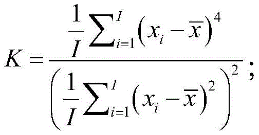
wherein K is the kurtosis value, x i In order to pre-set the eigenmode components, is the average value of a plurality of intrinsic mode components, and I is the number of the plurality of intrinsic mode components.
6. The method for identifying traveling wave of power distribution network fault of claim 1, wherein the instantaneous Teager's energy comprises: continuous signal energy and discrete signal energy;
the calculating the instantaneous Teager energy of the preset eigenmode component specifically comprises:
calculating the continuous signal energy of the preset eigenmode component according to a continuous signal energy calculation formula;
and calculating the discrete signal energy of the preset intrinsic mode component according to a discrete signal energy calculation formula.
7. The utility model provides a distribution network trouble travelling wave recognition device which characterized in that includes:
the acquisition unit is used for acquiring a traveling wave signal to be analyzed of the power distribution network to be analyzed;
the decomposition unit is used for carrying out variation mode decomposition on the traveling wave signal to be analyzed to obtain a plurality of intrinsic mode components;
the first calculating unit is used for calculating the kurtosis value of a preset eigenmode component from the plurality of eigenmode components;
the second calculation unit is used for calculating the instantaneous Teager energy of the preset intrinsic mode component when the kurtosis value is larger than a preset threshold value;
and the determining unit is used for determining the fault occurrence time of the traveling wave signal to be analyzed according to the instantaneous Teager energy so as to identify the fault traveling wave of the power distribution network.
8. The method for identifying traveling waves in power distribution network faults according to claim 7, wherein the decomposition unit specifically comprises:
the acquiring subunit is used for acquiring a plurality of initial modal components corresponding to the traveling wave signal to be analyzed;
the first calculating subunit is used for carrying out variation modal decomposition on the traveling wave signal to be analyzed, and calculating a new modal component by using an alternative direction multiplier method during each iteration;
and the second calculation subunit is used for stopping iteration when the new modal components obtained in two adjacent iterations meet the preset relational expression, and obtaining a plurality of intrinsic modal components by using the new modal components obtained in the second calculation in two adjacent iterations.
9. A power distribution network fault traveling wave identification device is characterized by comprising a processor and a memory;
the memory is used for storing program codes and transmitting the program codes to the processor;
the processor is configured to execute the power distribution network fault traveling wave identification method according to any one of claims 1 to 6 according to instructions in the program code.
10. A storage medium, characterized in that the storage medium is used for storing program code, and the program code realizes the power distribution network fault traveling wave identification method according to any one of claims 1 to 6 when executed by a processor.
Priority Applications (1)
| Application Number | Priority Date | Filing Date | Title |
|---|---|---|---|
| CN202211130459.4A CN115327302A (en) | 2022-09-15 | 2022-09-15 | Method, device and storage medium for identifying fault traveling wave of power distribution network |
Applications Claiming Priority (1)
| Application Number | Priority Date | Filing Date | Title |
|---|---|---|---|
| CN202211130459.4A CN115327302A (en) | 2022-09-15 | 2022-09-15 | Method, device and storage medium for identifying fault traveling wave of power distribution network |
Publications (1)
| Publication Number | Publication Date |
|---|---|
| CN115327302A true CN115327302A (en) | 2022-11-11 |
Family
ID=83929531
Family Applications (1)
| Application Number | Title | Priority Date | Filing Date |
|---|---|---|---|
| CN202211130459.4A Pending CN115327302A (en) | 2022-09-15 | 2022-09-15 | Method, device and storage medium for identifying fault traveling wave of power distribution network |
Country Status (1)
| Country | Link |
|---|---|
| CN (1) | CN115327302A (en) |
Cited By (3)
| Publication number | Priority date | Publication date | Assignee | Title |
|---|---|---|---|---|
| CN118567986A (en) * | 2024-06-04 | 2024-08-30 | 中国铁道科学研究院集团有限公司 | Data processing method and processing system for movable mould test platform of railway traction substation |
| CN119757956A (en) * | 2024-12-11 | 2025-04-04 | 云南电网有限责任公司电力科学研究院 | Fault traveling wave head calibration method, device, equipment and storage medium |
| CN119805091A (en) * | 2024-12-20 | 2025-04-11 | 国网冀北电力有限公司电力科学研究院 | Distribution network high resistance grounding fault detection method and device |
Citations (7)
| Publication number | Priority date | Publication date | Assignee | Title |
|---|---|---|---|---|
| WO2017031581A1 (en) * | 2015-08-24 | 2017-03-02 | UNIVERSITé LAVAL | System and method for detecting spikes in noisy signals |
| CN110542828A (en) * | 2019-07-17 | 2019-12-06 | 佛山电力设计院有限公司 | Distribution network fault positioning method and system |
| CN112710925A (en) * | 2020-12-22 | 2021-04-27 | 三峡大学 | High-permeability active power distribution network fault location method based on improved VMD and S transformation |
| CN112836583A (en) * | 2021-01-05 | 2021-05-25 | 沈阳工业大学 | A kind of wind turbine fault diagnosis method |
| CN113052000A (en) * | 2021-02-04 | 2021-06-29 | 江苏科技大学 | Early weak fault signal characteristic diagnosis method for ship mechanical equipment |
| CN113960412A (en) * | 2021-10-20 | 2022-01-21 | 南方电网科学研究院有限责任公司 | Method and device for processing fault traveling wave signals of power distribution network |
| CN114636896A (en) * | 2022-03-11 | 2022-06-17 | 西安理工大学 | Single-phase grounding high-resistance fault traveling wave positioning method for power distribution network by utilizing kurtosis |
-
2022
- 2022-09-15 CN CN202211130459.4A patent/CN115327302A/en active Pending
Patent Citations (8)
| Publication number | Priority date | Publication date | Assignee | Title |
|---|---|---|---|---|
| WO2017031581A1 (en) * | 2015-08-24 | 2017-03-02 | UNIVERSITé LAVAL | System and method for detecting spikes in noisy signals |
| CN110542828A (en) * | 2019-07-17 | 2019-12-06 | 佛山电力设计院有限公司 | Distribution network fault positioning method and system |
| CN112710925A (en) * | 2020-12-22 | 2021-04-27 | 三峡大学 | High-permeability active power distribution network fault location method based on improved VMD and S transformation |
| CN112836583A (en) * | 2021-01-05 | 2021-05-25 | 沈阳工业大学 | A kind of wind turbine fault diagnosis method |
| CN113052000A (en) * | 2021-02-04 | 2021-06-29 | 江苏科技大学 | Early weak fault signal characteristic diagnosis method for ship mechanical equipment |
| WO2022165737A1 (en) * | 2021-02-04 | 2022-08-11 | 江苏科技大学 | Method for diagnosing early weak fault signal features of marine machinery |
| CN113960412A (en) * | 2021-10-20 | 2022-01-21 | 南方电网科学研究院有限责任公司 | Method and device for processing fault traveling wave signals of power distribution network |
| CN114636896A (en) * | 2022-03-11 | 2022-06-17 | 西安理工大学 | Single-phase grounding high-resistance fault traveling wave positioning method for power distribution network by utilizing kurtosis |
Non-Patent Citations (5)
| Title |
|---|
| MINQIANG DENG 等: "Bandwidth Fourier decomposition and its application in incipient fault identification of rolling bearings", MEASUREMENT SCIENCE AND TECHNOLOGY, vol. 31, no. 1, 25 October 2019 (2019-10-25), pages 951 - 955, XP020348688, DOI: 10.1088/1361-6501/ab4069 * |
| 孙立江;张力佳;杜必强;邸薇薇;刘建屏;马延会;: "基于改进小波阈值和Teager能量算子的轴承故障诊断", 华北电力技术, no. 02, 25 February 2017 (2017-02-25), pages 38 - 43 * |
| 槐青: "柔性直流输电线路保护与故障测距方法研究", 中国博士学位论文全文数据库 工程科技Ⅱ辑, no. 6, 15 June 2022 (2022-06-15), pages 042 - 20 * |
| 毕潇文 等: "基于改进奇异值与经验小波分解的局放去噪算法", 电网技术, vol. 45, no. 12, 31 December 2021 (2021-12-31), pages 1 - 7 * |
| 焦亚博 等: "基于变分模态分解的综放工作面煤岩性状特征指标提取", 中央高校基本科研业务费项目研究成果论文集 2016 下, 31 January 2017 (2017-01-31), pages 958 - 961 * |
Cited By (3)
| Publication number | Priority date | Publication date | Assignee | Title |
|---|---|---|---|---|
| CN118567986A (en) * | 2024-06-04 | 2024-08-30 | 中国铁道科学研究院集团有限公司 | Data processing method and processing system for movable mould test platform of railway traction substation |
| CN119757956A (en) * | 2024-12-11 | 2025-04-04 | 云南电网有限责任公司电力科学研究院 | Fault traveling wave head calibration method, device, equipment and storage medium |
| CN119805091A (en) * | 2024-12-20 | 2025-04-11 | 国网冀北电力有限公司电力科学研究院 | Distribution network high resistance grounding fault detection method and device |
Similar Documents
| Publication | Publication Date | Title |
|---|---|---|
| Paternina et al. | Identification of electromechanical oscillatory modes based on variational mode decomposition | |
| CN115327302A (en) | Method, device and storage medium for identifying fault traveling wave of power distribution network | |
| CN103996077B (en) | A Method of Electrical Equipment Fault Prediction Based on Multidimensional Time Series | |
| CN106845010B (en) | Identification method of low frequency oscillation dominant mode based on improved SVD noise reduction and Prony | |
| CN108469560A (en) | A kind of objective complexity evaluation methodology of electromagnetic interference based on quick S-transformation time frequency space model | |
| CN104331583B (en) | A kind of Multifractal Modeling method based on Observed sea clutter | |
| CN114397569A (en) | Circuit breaker fault arc detection method based on VMD parameter optimization and sample entropy | |
| CN114184870A (en) | Non-invasive load identification method and device | |
| CN116679161A (en) | A power grid line fault diagnosis method, equipment and medium | |
| CN118962318B (en) | Cable early fault detection method based on segmented Teager-Kaiser energy operator | |
| CN119716393B (en) | A method for detecting and locating faults in power distribution network cables with enhanced noise resistance | |
| CN106501602A (en) | One kind is based on the detached fundamental wave measurement method of parameters of sliding window frequency spectrum | |
| CN118275824A (en) | Intelligent detection and early warning method based on ring network box and related equipment | |
| CN119936564A (en) | A fault location method and system for 35kV wind farm collector line | |
| CN119247033A (en) | Distribution network hidden fault identification method, device, electronic equipment and storage medium | |
| CN114034966A (en) | A method and device for fault identification of transmission line based on support vector machine | |
| CN120652201B (en) | Fault detection method and system for virtual power plant micro-grid | |
| CN119510980A (en) | A method for online fault detection in medium and low voltage distribution networks based on cross wavelet coherence analysis | |
| CN116628620B (en) | A non-intrusive load identification calculation method | |
| CN118798313A (en) | Training of generative adversarial network, current reconstruction method, device and storage medium | |
| CN111369179A (en) | Closed-loop detection method and device for distribution automation terminal equipment | |
| CN104730384A (en) | Power disturbance identification and localization method based on incomplete S transformation | |
| CN117872039B (en) | Line fault location method and system based on improved RBF network | |
| CN120275752B (en) | Intelligent power distribution monitoring system and method | |
| CN119805091B (en) | Methods and devices for detecting high-resistance grounding faults in power distribution networks |
Legal Events
| Date | Code | Title | Description |
|---|---|---|---|
| PB01 | Publication | ||
| PB01 | Publication | ||
| SE01 | Entry into force of request for substantive examination | ||
| SE01 | Entry into force of request for substantive examination | ||
| RJ01 | Rejection of invention patent application after publication | ||
| RJ01 | Rejection of invention patent application after publication |
Application publication date: 20221111 |