CN115230839A - Thrust control method for wall-climbing robot - Google Patents
Thrust control method for wall-climbing robot Download PDFInfo
- Publication number
- CN115230839A CN115230839A CN202211136590.1A CN202211136590A CN115230839A CN 115230839 A CN115230839 A CN 115230839A CN 202211136590 A CN202211136590 A CN 202211136590A CN 115230839 A CN115230839 A CN 115230839A
- Authority
- CN
- China
- Prior art keywords
- thrust
- duct
- rotary
- included angle
- rotating
- Prior art date
- Legal status (The legal status is an assumption and is not a legal conclusion. Google has not performed a legal analysis and makes no representation as to the accuracy of the status listed.)
- Granted
Links
- 238000000034 method Methods 0.000 title claims abstract description 24
- 230000005484 gravity Effects 0.000 claims abstract description 58
- 230000001133 acceleration Effects 0.000 claims description 38
- 238000009434 installation Methods 0.000 claims description 6
- 238000004364 calculation method Methods 0.000 claims description 5
- 238000005259 measurement Methods 0.000 abstract description 5
- 230000002159 abnormal effect Effects 0.000 description 2
- 230000009194 climbing Effects 0.000 description 2
- 238000001179 sorption measurement Methods 0.000 description 2
- 238000009825 accumulation Methods 0.000 description 1
- 238000004140 cleaning Methods 0.000 description 1
- 238000010586 diagram Methods 0.000 description 1
- 238000012986 modification Methods 0.000 description 1
- 230000004048 modification Effects 0.000 description 1
- 230000000630 rising effect Effects 0.000 description 1
- 238000006467 substitution reaction Methods 0.000 description 1
- 239000000725 suspension Substances 0.000 description 1
- XLYOFNOQVPJJNP-UHFFFAOYSA-N water Substances O XLYOFNOQVPJJNP-UHFFFAOYSA-N 0.000 description 1
Images
Classifications
-
- G—PHYSICS
- G05—CONTROLLING; REGULATING
- G05D—SYSTEMS FOR CONTROLLING OR REGULATING NON-ELECTRIC VARIABLES
- G05D1/00—Control of position, course, altitude or attitude of land, water, air or space vehicles, e.g. using automatic pilots
- G05D1/08—Control of attitude, i.e. control of roll, pitch, or yaw
- G05D1/0891—Control of attitude, i.e. control of roll, pitch, or yaw specially adapted for land vehicles
-
- B—PERFORMING OPERATIONS; TRANSPORTING
- B62—LAND VEHICLES FOR TRAVELLING OTHERWISE THAN ON RAILS
- B62D—MOTOR VEHICLES; TRAILERS
- B62D57/00—Vehicles characterised by having other propulsion or other ground- engaging means than wheels or endless track, alone or in addition to wheels or endless track
- B62D57/02—Vehicles characterised by having other propulsion or other ground- engaging means than wheels or endless track, alone or in addition to wheels or endless track with ground-engaging propulsion means, e.g. walking members
- B62D57/024—Vehicles characterised by having other propulsion or other ground- engaging means than wheels or endless track, alone or in addition to wheels or endless track with ground-engaging propulsion means, e.g. walking members specially adapted for moving on inclined or vertical surfaces
-
- B—PERFORMING OPERATIONS; TRANSPORTING
- B62—LAND VEHICLES FOR TRAVELLING OTHERWISE THAN ON RAILS
- B62D—MOTOR VEHICLES; TRAILERS
- B62D57/00—Vehicles characterised by having other propulsion or other ground- engaging means than wheels or endless track, alone or in addition to wheels or endless track
- B62D57/04—Vehicles characterised by having other propulsion or other ground- engaging means than wheels or endless track, alone or in addition to wheels or endless track having other than ground-engaging propulsion means, e.g. having propellers
-
- B—PERFORMING OPERATIONS; TRANSPORTING
- B64—AIRCRAFT; AVIATION; COSMONAUTICS
- B64C—AEROPLANES; HELICOPTERS
- B64C27/00—Rotorcraft; Rotors peculiar thereto
- B64C27/04—Helicopters
- B64C27/08—Helicopters with two or more rotors
-
- B—PERFORMING OPERATIONS; TRANSPORTING
- B64—AIRCRAFT; AVIATION; COSMONAUTICS
- B64C—AEROPLANES; HELICOPTERS
- B64C27/00—Rotorcraft; Rotors peculiar thereto
- B64C27/20—Rotorcraft characterised by having shrouded rotors, e.g. flying platforms
-
- B—PERFORMING OPERATIONS; TRANSPORTING
- B64—AIRCRAFT; AVIATION; COSMONAUTICS
- B64C—AEROPLANES; HELICOPTERS
- B64C27/00—Rotorcraft; Rotors peculiar thereto
- B64C27/52—Tilting of rotor bodily relative to fuselage
-
- G—PHYSICS
- G05—CONTROLLING; REGULATING
- G05D—SYSTEMS FOR CONTROLLING OR REGULATING NON-ELECTRIC VARIABLES
- G05D1/00—Control of position, course, altitude or attitude of land, water, air or space vehicles, e.g. using automatic pilots
- G05D1/02—Control of position or course in two dimensions
- G05D1/021—Control of position or course in two dimensions specially adapted to land vehicles
- G05D1/0268—Control of position or course in two dimensions specially adapted to land vehicles using internal positioning means
- G05D1/027—Control of position or course in two dimensions specially adapted to land vehicles using internal positioning means comprising intertial navigation means, e.g. azimuth detector
-
- B—PERFORMING OPERATIONS; TRANSPORTING
- B64—AIRCRAFT; AVIATION; COSMONAUTICS
- B64U—UNMANNED AERIAL VEHICLES [UAV]; EQUIPMENT THEREFOR
- B64U2101/00—UAVs specially adapted for particular uses or applications
- B64U2101/25—UAVs specially adapted for particular uses or applications for manufacturing or servicing
-
- B—PERFORMING OPERATIONS; TRANSPORTING
- B64—AIRCRAFT; AVIATION; COSMONAUTICS
- B64U—UNMANNED AERIAL VEHICLES [UAV]; EQUIPMENT THEREFOR
- B64U2201/00—UAVs characterised by their flight controls
- B64U2201/10—UAVs characterised by their flight controls autonomous, i.e. by navigating independently from ground or air stations, e.g. by using inertial navigation systems [INS]
Landscapes
- Engineering & Computer Science (AREA)
- Mechanical Engineering (AREA)
- Aviation & Aerospace Engineering (AREA)
- Radar, Positioning & Navigation (AREA)
- Combustion & Propulsion (AREA)
- Transportation (AREA)
- Chemical & Material Sciences (AREA)
- Remote Sensing (AREA)
- Physics & Mathematics (AREA)
- General Physics & Mathematics (AREA)
- Automation & Control Theory (AREA)
- Structures Of Non-Positive Displacement Pumps (AREA)
- Manipulator (AREA)
Abstract
The invention discloses a thrust control method of a wall-climbing robot, which comprises the steps of firstly, obtaining the posture direction of a body, wherein the posture direction comprises the angle of the body on a vertical plane, and calculating a first included angle between the posture direction of the body and the gravity direction; rotating the rotary duct according to the numerical value of the first included angle, and adjusting the thrust direction of the rotary duct to enable the thrust direction to be opposite to the gravity direction of the body; the thrust data obtained by measurement of the first pressure sensor are obtained, the rotating speed of the fan of the rotary duct is adjusted according to the thrust data, the thrust data are equal to the gravity value of the robot body, the direction and the thrust of the rotary duct are controlled, the thrust of the rotary duct is kept opposite to the gravity direction of the robot body in real time, the thrust of the rotary duct is kept to be the same as the gravity direction of the robot body, and the robot can be stably suspended on the wall surface.
Description
Technical Field
The embodiment of the invention relates to the field of robots, but not limited to the field of robots, in particular to a thrust control method for a wall-climbing robot.
Background
Along with technical progress, the air operation field is more and more replaced manual work by the robot, and current robot is used for the air operation field of lightweight mostly, in the consumption field for example be used for the unmanned aerial vehicle of shooting, adsorbs the window cleaning robot that is used for wiping the window in smooth surface, and industry field for example the boats and ships that inhale are overhauld the robot. In the field of engineering tunnels, the robots of the existing technical schemes such as negative pressure adsorption and magnetic adsorption can not normally work on rough tunnel walls because the walls are rough concrete or even concrete guniting. In the tunnel measurement operation, heavy measurement equipment needs to be carried to measure in the tunnel, meanwhile, the height of the side wall of the arched tunnel needs to be measured at the same time, the robot of the existing propeller flight scheme cannot carry a large load, and meanwhile, due to the special curved surface space environment of the tunnel, the appearance and the movement mode of the robot are also limited, and the propeller cannot safely fly and effectively measure. Further, in the tunnel, the robot dead weight is great, will carry heavy measuring equipment simultaneously, the robot that uses negative pressure technical scheme among the correlation technique adsorbs in the tunnel wall, booster fan through control fixing in on the machine, make the machine receive the negative pressure to be fixed in the wall, nevertheless if make heavy robot can stabilize in the tunnel curved surface, even negative angle's wall, booster fan needs very big thrust, make to produce frictional force between robot and the wall and be enough to offset gravity and stabilize in the wall, so big thrust requires extremely high to the voltage and the electric current of power supply, no matter the robot is wired connection power, still the robot carries the battery, in actual engineering practice, difficult to realize, and with high costs, the degree of difficulty is big, can seriously wear out the contact surface of robot and wall simultaneously. Therefore, in the related art of the robot thrust control, it is difficult to stably hold the robot on the wall surface only by controlling the negative pressure of the robot and the arched wall surface.
Disclosure of Invention
The following is a summary of the subject matter described in detail herein. This summary is not intended to limit the scope of the claims.
The embodiment of the invention provides a thrust control method of a wall-climbing robot, which is characterized in that the thrust direction of a rotary duct is opposite to the gravity direction of a robot body in real time and is the same as the gravity direction of the robot body by controlling the direction and the thrust of the rotary duct, so that the robot can be stably suspended at any position of an arched wall surface.
The embodiment of the invention provides a thrust control method of a wall-climbing robot, wherein the wall-climbing robot comprises a body, a plurality of rotary ducts for providing thrust and a first pressure sensor for acquiring thrust data corresponding to the rotary ducts, and the method comprises the following steps: acquiring the posture direction of the body, and calculating a first included angle between the posture direction of the body and the gravity direction; adjusting the thrust direction of the rotary duct according to the first included angle, so that the thrust direction of the rotary duct is opposite to the gravity direction; and acquiring the thrust data corresponding to the rotary duct, and adjusting the rotating speed of the fan of the rotary duct according to the thrust data to enable the thrust data to be equal to the gravity value of the body.
According to the above embodiments of the present application, at least the following advantages are provided: firstly, acquiring the attitude direction of the body, and calculating a first included angle between the attitude direction of the body and the gravity direction; rotating the rotary duct according to the numerical value of the first included angle, and adjusting the thrust direction of the rotary duct to enable the direction of the thrust to be opposite to the gravity direction of the body; the thrust data measured by the first pressure sensor are obtained, the rotating speed of the fan of the rotary duct is adjusted according to the thrust data, the thrust data are equal to the gravity value of the robot body, the thrust direction of the rotary duct is opposite to the gravity direction of the robot body in real time through controlling the direction and the thrust of the rotary duct, the thrust direction is the same as the gravity direction of the robot body, and the robot can be stably suspended at any position of the arched wall surface.
According to some embodiments of the invention, said adjusting the thrust direction of said rotating duct according to said first angle comprises: acquiring a rotation angular velocity corresponding to the attitude direction; obtaining a rotation direction of the body according to the rotation angular velocity; according to the first included angle and the rotating direction of the body, the rotating duct is rotated in the direction opposite to the rotating direction of the body, and the rotating angle of the rotating duct is the first included angle degree.
According to some embodiments of the invention, the wall-climbing robot further comprises an acceleration sensor for acquiring the acceleration of the body, and the method comprises: acquiring the direction of the body acceleration, and calculating a second included angle between the body acceleration in the vertical direction and the body gravity direction; and adjusting the rotating speed of the fan of the rotary duct according to the second included angle to enable the acceleration of the body to be zero in the vertical direction.
According to some embodiments of the invention, said adjusting the fan speed of the rotational duct according to the second angle to make the body acceleration value zero in the vertical direction comprises: under the condition that the second included angle is 0 degree, increasing the rotating speed of the fan of the rotating duct to enable the acceleration of the body to be zero in the vertical direction; and under the condition that the second included angle is 180 degrees, reducing the rotating speed of the fan of the rotating duct to enable the acceleration to be zero in the vertical direction.
According to some embodiments of the present invention, the wall-climbing robot further includes at least one fixed duct for providing pressure to a wall surface and a second pressure sensor for acquiring pressure data corresponding to the fixed duct, and the adjusting the fan speed of the rotating duct according to the second included angle includes: acquiring the pressure data corresponding to the fixed duct; under the condition that the second included angle is 0 degree, increasing the rotating speed of the fan of the fixed duct to enable the acceleration to be zero in the vertical direction; and stopping the rotating speed of the fan of the fixed duct under the condition that the second included angle is 180 degrees.
According to some embodiments of the present invention, the obtaining the thrust data corresponding to the rotational duct, and adjusting the rotational speed of the fan of the rotational duct according to the thrust data to make the thrust data equal to the gravity value of the body, includes: acquiring the thrust data corresponding to the plurality of first pressure sensors; carrying out vector calculation on the plurality of thrust data to obtain the numerical value and the direction of the resultant thrust force of the plurality of thrust data; and adjusting the rotating speeds of the fans of the plurality of rotary ducts according to the numerical value and the direction of the resultant thrust force.
According to some embodiments of the invention, the adjusting the fan speeds of the plurality of rotational ducts according to the value and the direction of the resultant thrust force comprises: acquiring corresponding preset installation force arms of the plurality of rotary ducts; calculating target thrust corresponding to the plurality of rotary ducts by using the mounting force arm according to lever balance; and adjusting the rotating speed of the fan of the rotary duct according to the target thrust and the thrust data corresponding to the rotary duct, so that the thrust data reaches the calculated target thrust.
According to some embodiments of the invention, said adjusting the fan speed of the rotational duct according to the target thrust and the thrust data corresponding to the rotational duct to bring the thrust data to the calculated target thrust comprises: calculating a horizontal included angle between the posture direction of the body and the horizontal direction; and adjusting the rotating speed of the fan of the rotary duct according to the horizontal included angle to enable the plurality of rotary ducts to be on the same horizontal line.
According to some embodiments of the invention, the control of the thrust data employs a PID control algorithm.
According to some embodiments of the invention, the control of the thrust direction of the rotational duct employs a PD control algorithm.
Additional features and advantages of the invention will be set forth in the description which follows, and in part will be obvious from the description, or may be learned by the practice of the invention. The objectives and other advantages of the invention will be realized and attained by the structure particularly pointed out in the written description and claims hereof as well as the appended drawings.
Drawings
The accompanying drawings are included to provide a further understanding of the present invention and are incorporated in and constitute a part of this specification, illustrate embodiments of the invention and together with the example serve to explain the principles of the invention and do not constitute a limitation thereof.
Fig. 1 is a main flow chart of a thrust control method for a wall-climbing robot according to an embodiment of the present invention;
fig. 2 is a schematic view of a wall-climbing robot according to an embodiment of the present invention.
Detailed Description
In order to make the objects, technical solutions and advantages of the present invention more apparent, the present invention is described in further detail below with reference to the accompanying drawings and embodiments. It should be understood that the specific embodiments described herein are merely illustrative of the invention and are not intended to limit the invention.
It should be understood that in the description of the embodiments of the present invention, a plurality (or a plurality) means two or more, more than, less than, more than, etc. are understood as excluding the number, and more than, less than, etc. are understood as including the number. The vertical direction refers to the direction same as or opposite to the gravity direction, and is determined to belong to the same or opposite according to specific conditions, if the description of "first", "second", and the like is only used for distinguishing technical features, and the description cannot be understood as indicating or implying relative importance or implicitly indicating the number of the indicated technical features or implicitly indicating the precedence relationship of the indicated technical features.
In the related art of the tunnel measuring work, it is difficult to stably hold the robot on the wall surface only by controlling the negative pressure of the robot and the arched wall surface. Therefore, in order to solve the existing problems, embodiments of the present invention provide a thrust control method for a wall-climbing robot, which controls the direction and thrust of the rotary duct 200, so as to keep the thrust direction of the rotary duct 200 opposite to the gravity direction of the robot body 100 and keep the same in magnitude in real time, and thus the robot can stably suspend on a wall surface. The wall-climbing robot thrust control method provided by the embodiment of the invention is applied to a wall-climbing robot, the wall-climbing robot comprises a body 100, a plurality of rotary ducts 200 for providing thrust, and a first pressure sensor for acquiring thrust data corresponding to the rotary ducts 200, wherein firstly, the posture direction of the body 100 is acquired, the posture direction comprises the angle of the body 100 on a vertical plane, and a first included angle between the posture direction of the body 100 and the gravity direction is calculated; rotating the rotary duct 200 according to the value of the first included angle, and adjusting the thrust direction of the rotary duct 200 to make the thrust direction opposite to the gravity direction of the body 100; thrust data measured by the first pressure sensor is obtained, the rotating speed of the fan of the rotary duct 200 is adjusted according to the thrust data, the thrust data are equal to the gravity value of the robot body 100, the direction and the thrust of the rotary duct 200 are controlled, the thrust direction of the rotary duct 200 is opposite to the gravity direction of the robot body 100 in real time, the thrust direction and the gravity direction are the same, and the robot can stably suspend on the wall surface.
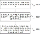
As shown in fig. 1, fig. 1 is a flowchart of a thrust control method for a wall climbing robot according to an embodiment of the present invention. The thrust control method of the wall climbing robot comprises the following steps:
step S100, acquiring the posture direction of the body 100, and calculating a first included angle between the posture direction of the body 100 and the gravity direction;
step S200, adjusting the thrust direction of the rotary duct 200 according to the first included angle to enable the thrust direction to be opposite to the gravity direction of the body 100;
step S300, obtaining the thrust data, and adjusting the rotation speed of the fan rotating the duct 200 according to the thrust data, so that the thrust data is equal to the gravity value of the body 100.
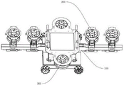
It can be understood that, as shown in fig. 2, fig. 2 is a schematic diagram of a wall-climbing robot provided in this embodiment, first obtaining a posture direction of the body 100, where the posture direction includes an angle of the body 100 on a vertical plane, and calculating a first included angle between the posture direction of the body 100 and a gravity direction; rotating the rotary duct 200 according to the value of the first included angle, and adjusting the thrust direction of the rotary duct 200 to make the thrust direction opposite to the gravity direction of the body 100; the thrust data measured by the first pressure sensor are obtained, the rotating speed of the fan of the rotary duct 200 is adjusted according to the thrust data, the thrust data are equal to the gravity value of the robot body 100, the direction and the thrust of the rotary duct 200 are controlled, the thrust direction of the rotary duct 200 is opposite to the gravity direction of the robot body 100 in real time, the thrust direction and the thrust are the same in size, and the robot can be stably suspended on the wall surface. Specifically, the rotary duct 200 is fixed to the robot body 100, in this embodiment, the rotary duct 200 rotates around a shaft, that is, the rotary duct 200 is fixed to the robot body 100, in this embodiment, a bearing frame is arranged on the robot body 100, the bearing frame is in a straight shape, the rotary duct 200 is fixed to the bearing frame in a straight shape, the number of the rotary ducts 200 is multiple, in this embodiment, there are 4 rotary ducts 200, the rotary ducts 200 are symmetrically arranged on two sides of the center of gravity of the robot body 100, that is, the left side is provided with 2 rotary ducts 200, the right side is provided with 2 rotary ducts 200, the rotation direction of the rotary ducts 200 is perpendicular to the axis of the bearing frame, and the axis of the bearing frame is parallel to the direction in which the robot advances along the horizontal direction. When the robot is on the wall surface, the axis of the bearing frame is in the horizontal direction, the attitude direction of the robot body 100 is firstly obtained, the attitude direction is obtained by comparing the current attitude direction of the body 100 with the reference to the initial attitude direction, the initial attitude direction is the attitude direction of the robot measured by a gyroscope installed in the body 100 when the robot is placed on the horizontal ground, after the attitude direction is established, when the robot is in different positions of the tunnel curved surface, the change of the attitude direction of the robot on the curved surface can be calculated according to the initial attitude direction, the included angle between the initial attitude direction and the gravity direction is set, the first included angle between the attitude direction of the body 100 and the gravity direction can be calculated according to the included angle, it can be understood that the pitch angle of the robot is detected by the gyroscope, the first included angle between the attitude direction of the body 100 and the gravity direction is calculated according to the pitch angle, because the rotary duct 200 is also fixed to the robot body 100, the rotary duct 200 has the same change according to the change of the attitude direction of the robot body 100, therefore, according to the attitude direction of the rotary duct 200 rotates in the direction opposite to the direction of the body 100, the gravity, namely, the rotary duct 200 rotates in the direction opposite to the direction of the thrust direction, and the direction of the gravity direction of the rotary duct 200, and the thrust direction of the rotary duct 200, and the direction of the rotary duct 200 rotate. In this embodiment, the first pressure sensor is disposed at a position where the robot body 100 is connected to the rotational duct 200, and may detect the pressure between the rotational duct 200 and the body 100 in real time. Therefore, the real-time thrust of the rotary duct 200 is known according to the thrust data monitored by the first pressure sensor, the gravity of the robot can be a preset value or a real-time measured value, and the thrust of the rotary duct 200 is adjusted, so that the thrust data is opposite to the direction of the gravity and has the same size.
It can be understood that, in yet another embodiment, the wall-climbing robot further includes an acceleration sensor for acquiring the acceleration of the body 100, and the acceleration sensor acquires the direction of the acceleration of the body 100, and calculates a second included angle between the component of the acceleration in the vertical direction and the gravity direction of the body 100; the rotating speed of the fan of the rotary duct 200 is adjusted according to the second included angle, so that the value of the acceleration is zero in the vertical direction, specifically, when the robot moves on the wall surface, when an accident occurs, for example, the supply voltage or the current of the rotary duct 200 changes instantaneously, the rotating speed of the fan of the rotary duct 200 changes suddenly, so that the robot falls or flies, at the moment, the acceleration sensor can detect that the posture of the robot is abnormal, the second included angle between the component of the acceleration direction in the vertical direction obtained by the acceleration sensor and the gravity direction is calculated, and whether the robot is in an abnormal motion state or not can be judged according to the change of the second included angle. When the robot falls or flies, the acceleration measured by the acceleration sensor is not zero, and the value of the acceleration in the vertical direction is zero by reversely controlling the rotating speed of the fan of the rotary duct 200, and the vertical direction can be understood as the direction in a straight line with the gravity direction.
It can be understood that the rotational speed of the fan rotating the duct 200 is adjusted according to the second included angle so that the acceleration is zero in the vertical direction, and when the second included angle is 0 degree, the rotational speed of the fan rotating the duct 200 is increased so that the acceleration is zero in the vertical direction; when the second included angle is 180 degrees, the rotational speed of the fan rotating the duct 200 is reduced, so that the acceleration is zero in the vertical direction. Specifically, when the second included angle is 0 degree, that is, the direction of the acceleration is the same as the gravity direction of the robot, that is, the robot suddenly falls down, at this time, the rotation speed of the fan of the rotary duct 200 needs to be increased, the thrust is used to resist the tendency that the robot quickly falls down, so that the falling speed of the robot is reduced, the robot gradually reduces the speed, and the value of the acceleration in the vertical direction is gradually zero; when the second included angle is 180 degrees, that is, the direction of the acceleration is opposite to the gravity direction of the robot, that is, because the thrust of the rotational duct 200 is too large, the robot flies upward, and at this time, the rotational speed of the fan that rotates the duct 200 needs to be reduced, and the thrust of the rotational duct 200 is reduced, so that the robot stops rising, even if the value of the acceleration in the vertical direction is zero.
It is understood that, in another embodiment, the wall-climbing robot further comprises at least one fixed duct 300 for providing pressure and a second pressure sensor for acquiring pressure data, and the rotating speed of the fan rotating the duct 200 is adjusted according to the second included angle to acquire the pressure data; when the second included angle is 0 degree, increasing the rotating speed of the fan of the fixed duct 300 to make the acceleration value in the vertical direction zero; when the second included angle is 180 degrees, the rotation speed of the fan fixing the duct 300 is stopped. Specifically, the robot body 100 is provided with at least one fixed duct 300, in this embodiment, 2 fixed ducts 300 are provided and symmetrically disposed at two ends of the center of gravity of the robot body 100, when the robot is located on a wall surface, the air outlet direction of the fixed duct 300 is perpendicular to and far away from the wall surface, the second pressure sensor is disposed at the connection between the robot body 100 and the fixed duct 300, and can detect the pressure of the fixed duct 300 on the body 100 in real time, therefore, in this embodiment, when the second included angle is 0 degree, i.e., the robot accidentally falls, and rapidly falls, at this time, the emergency mode needs to be started, the fan rotation speed of the fixed duct 300 is increased, the pressure of the fixed duct 300 on the body 100 is increased, so that the friction of the wall surface of the robot on the robot is increased, the tendency of the robot falling is reduced, the falling is reduced by the friction force assisting the rotary duct 200, and the value in the vertical direction is gradually zero, i.e., the robot stops falling and suspends in the air. When the second included angle is 180 degrees, that is, the robot is in an upward flying state, that is, the thrust of the rotary duct 200 is too large, or the robot is moving upward, which does not belong to an emergency mode of a safety problem at this time, it is not necessary to adjust the friction force through the fixed duct 300 to affect the moving state of the rotary duct 200, and therefore, the rotation speed of the fan of the fixed duct 300 is stopped, and the friction force is made to be zero.
It is understood that, in the present embodiment, thrust data corresponding to a plurality of first pressure sensors is acquired; vector calculation is carried out on the plurality of thrust data, and the numerical value and the direction of the resultant thrust force of the plurality of thrust data are obtained; the rotation speeds of the fans of the plurality of rotational ducts 200 are adjusted according to the numerical value and the direction of the resultant thrust force. Since the plurality of rotary ducts 200 are fixed to the robot body 100, the plurality of rotary ducts 200 generate a plurality of thrusts, and vector calculation is performed on the plurality of thrusts according to force analysis, specifically, in this embodiment, the rotary ducts 200 are symmetrically disposed on two sides of the center of gravity of the robot body 100, so that the resultant force of the thrusts is the accumulation of the plurality of thrusts.
It can be understood that, according to the numerical value and the direction of the resultant thrust force, the fan rotation speed of the plurality of rotary ducts 200 is adjusted to obtain the preset installation force arms corresponding to the plurality of rotary ducts 200; calculating the thrust corresponding to the plurality of rotary ducts 200 by using the installation force arms according to the lever balance; and adjusting the rotating speed of the fan according to the calculated thrust magnitude corresponding to the plurality of rotary ducts 200, so that the thrust data reaches the calculated thrust magnitude corresponding to the plurality of rotary ducts 200. Specifically, since the plurality of rotary ducts 200 are fixedly mounted on the robot body 100 to generate a plurality of thrusts, the plurality of thrusts need to be subjected to vector calculation, and when the thrusts are symmetrically distributed on two sides of the center of gravity of the robot, the thrusts of the rotary ducts 200 are set to be the same thrust, and the thrust values of the rotary ducts 200 are adjusted in an equivalent manner, so that the resultant thrust force of the rotary ducts 200 can be rapidly equal to the gravity of the robot; when the rotary ducts 200 are not uniformly and symmetrically distributed on two sides of the center of gravity of the robot, according to the lever balance principle, the thrust force distribution proportion of each rotary duct 200 is calculated according to the force arm proportion of each rotary duct 200, and then the thrust force is calculated.
It can be understood that the installation force arms corresponding to the plurality of rotary ducts 200 are symmetrically and equally arranged along the center of gravity of the body 100, specifically, the plurality of rotary ducts 200 are symmetrically arranged on two sides of the center of gravity of the robot, and the distances between the rotary ducts are the same.
It can be understood that an included angle between the air volume of the posture direction of the body 100 in the horizontal direction and the horizontal line is calculated, and the rotation speed of the fan of the rotational duct 200 is adjusted according to the included angle in the horizontal direction, so that the plurality of rotational ducts 200 are on the same horizontal line. Specifically, there is the contained angle when the horizontal component of the gesture direction of body 100 and water line, and the bearing frame of a style of calligraphy is not at the horizontality promptly, and the rotation duct 200 of bearing frame installation does not have balanced being in the horizontal line, can make the robot gesture crooked like this, consequently, need adjust the fan rotational speed of the rotation duct 200 that corresponds according to crooked contained angle, make the robot gesture resume the level. That is, to which side the robot posture is deviated, the rotation speed of the fan of the rotation duct 200 of the same side is increased, so that the robot posture is corrected.
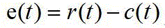
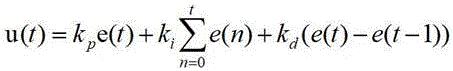
It will be appreciated that the control of the thrust data employs a PID control algorithm, and in particular, the following control algorithm:
wherein:
r (t): the calculated thrust.
c (t): the thrust resultant corresponding to the current rotational duct 200.
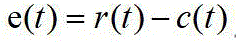
e (t): and the error of the calculated thrust and the current thrust resultant force.
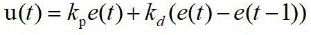
u (t): and calculating an adjusting value of the resultant thrust force according to the calculated thrust force and the current resultant thrust force.
Through the PD control algorithm, the rotating speed of the fan of the rotary duct 200 can be adjusted in real time, and the thrust can be adjusted in real time according to the real-time change of the robot, so that the robot can be stably suspended at any position of the arched wall surface of the tunnel, and the accurate measurement requirement of the robot is ensured.
It is understood that the control of the thrust direction of the rotational duct 200 employs a PD control algorithm, and in particular, employs the following control algorithm:
wherein:
r (t): a desired pose.
c (t): the current pose.
e (t): error of the desired pose from the current pose.
u (t): and calculating a posture adjustment value according to the expected posture and the current posture.
Through PD control algorithm, can adjust the orientation of rotating duct 200 immediately, adjust the thrust direction of rotating duct 200 promptly, immediately according to the real-time change of robot gesture, adjust the thrust direction, make the thrust direction that rotates duct 200 all the time with the robot gravity direction opposite, the size is the same for the robot can remain stable suspension in the optional position of tunnel arch wall, guarantees the accurate measurement requirement of robot.
While the preferred embodiments of the present invention have been described, it will be understood by those skilled in the art that the present invention is not limited to the above embodiments, and various equivalent modifications or substitutions can be made without departing from the spirit of the present invention and the scope of the present invention is defined by the appended claims.
Claims (9)
1. A thrust control method for a wall-climbing robot is characterized in that the wall-climbing robot comprises a body, a plurality of rotary ducts for providing thrust, a first pressure sensor for acquiring thrust data corresponding to the rotary ducts, and an acceleration sensor for acquiring acceleration of the body, and the method comprises the following steps:
acquiring the posture direction of the body, and calculating a first included angle between the posture direction and the gravity direction;
adjusting the thrust direction of the rotary duct according to the first included angle, so that the thrust direction of the rotary duct is opposite to the gravity direction;
acquiring the thrust data corresponding to the rotary duct, and adjusting the fan rotating speed of the rotary duct according to the thrust data to enable the thrust data to be equal to the gravity value of the body;
acquiring the direction of the body acceleration, and calculating a second included angle between the body acceleration in the vertical direction and the gravity direction of the body;
and adjusting the rotating speed of the fan of the rotary duct according to the second included angle to enable the acceleration of the body to be zero in the vertical direction.
2. The method of claim 1, wherein said adjusting a thrust direction of said rotating duct according to said first included angle comprises:
acquiring a rotation angular velocity corresponding to the attitude direction;
obtaining a rotation direction of the body according to the rotation angular velocity;
according to the first included angle and the rotating direction of the body, the rotating duct is rotated in the direction opposite to the rotating direction of the body, and the rotating angle of the rotating duct is the first included angle degree.
3. The method of claim 1, wherein said adjusting the rotational speed of the fan of the rotational duct according to the second included angle to a value of zero acceleration of the body in the vertical direction comprises:
under the condition that the second included angle is 0 degree, increasing the rotating speed of the fan of the rotating duct to enable the acceleration of the body to be zero in the vertical direction;
and under the condition that the second included angle is 180 degrees, reducing the rotating speed of the fan of the rotating duct to enable the acceleration to be zero in the vertical direction.
4. The method of claim 1, wherein the wall-climbing robot further comprises at least one fixed duct for providing pressure to the wall surface and a second pressure sensor for acquiring pressure data corresponding to the fixed duct, and wherein adjusting the fan speed of the rotating duct according to the second included angle comprises:
acquiring the pressure data corresponding to the fixed duct;
under the condition that the second included angle is 0 degree, increasing the rotating speed of the fan of the fixed duct to enable the acceleration to be zero in the vertical direction;
and under the condition that the second included angle is 180 degrees, stopping the rotating speed of the fan of the fixed duct.
5. The method of claim 4, wherein the obtaining the thrust data corresponding to the rotational duct and adjusting the fan speed of the rotational duct based on the thrust data to equalize the thrust data to the gravity value of the body comprises:
acquiring the thrust data corresponding to the plurality of first pressure sensors;
performing vector calculation on the plurality of thrust data to obtain the numerical value and the direction of the resultant thrust force of the plurality of thrust data;
and adjusting the rotating speeds of the fans of the plurality of rotary ducts according to the numerical value and the direction of the resultant thrust force.
6. The method of claim 5, wherein said adjusting the fan speed of a plurality of said rotational ducts based on the magnitude and direction of said resultant thrust force comprises:
acquiring corresponding preset installation force arms of the plurality of rotary ducts;
calculating target thrust corresponding to the plurality of rotary ducts by using the mounting force arm according to lever balance;
and adjusting the rotating speed of the fan of the rotary duct according to the target thrust and the thrust data corresponding to the rotary duct, so that the thrust data reaches the calculated target thrust.
7. The method of claim 6, wherein said adjusting a fan speed of said rotating duct based on said target thrust and said thrust data corresponding to said rotating duct to bring said thrust data to said calculated target thrust comprises:
calculating a horizontal included angle between the posture direction of the body and the horizontal direction;
and adjusting the rotating speed of the fan of the rotary duct according to the horizontal included angle to enable the plurality of rotary ducts to be on the same horizontal line.
8. The method of claim 7, wherein the control of the thrust data employs a PID control algorithm.
9. The method of claim 8, wherein the controlling of the thrust direction of the rotational duct employs a PD control algorithm.
Priority Applications (2)
| Application Number | Priority Date | Filing Date | Title |
|---|---|---|---|
| CN202211136590.1A CN115230839B (en) | 2022-09-19 | 2022-09-19 | Thrust control method for wall-climbing robot |
| EP23197966.7A EP4339728B1 (en) | 2022-09-19 | 2023-09-18 | Thrust control method for wall-climbing robot |
Applications Claiming Priority (1)
| Application Number | Priority Date | Filing Date | Title |
|---|---|---|---|
| CN202211136590.1A CN115230839B (en) | 2022-09-19 | 2022-09-19 | Thrust control method for wall-climbing robot |
Publications (2)
| Publication Number | Publication Date |
|---|---|
| CN115230839A true CN115230839A (en) | 2022-10-25 |
| CN115230839B CN115230839B (en) | 2023-01-17 |
Family
ID=83681966
Family Applications (1)
| Application Number | Title | Priority Date | Filing Date |
|---|---|---|---|
| CN202211136590.1A Active CN115230839B (en) | 2022-09-19 | 2022-09-19 | Thrust control method for wall-climbing robot |
Country Status (2)
| Country | Link |
|---|---|
| EP (1) | EP4339728B1 (en) |
| CN (1) | CN115230839B (en) |
Cited By (1)
| Publication number | Priority date | Publication date | Assignee | Title |
|---|---|---|---|---|
| CN118625848A (en) * | 2024-08-14 | 2024-09-10 | 河北工业大学 | Robot control method |
Families Citing this family (2)
| Publication number | Priority date | Publication date | Assignee | Title |
|---|---|---|---|---|
| CN120064437B (en) * | 2025-02-25 | 2026-02-10 | 哈尔滨工程大学 | Automatic detection robot for large pressure vessel |
| CN120213940A (en) * | 2025-03-25 | 2025-06-27 | 广州大学 | A device and method for detecting damage of underwater bridge pile foundation |
Citations (10)
| Publication number | Priority date | Publication date | Assignee | Title |
|---|---|---|---|---|
| US20130168489A1 (en) * | 2012-01-04 | 2013-07-04 | James William McIntee | Roadable, Adaptable-Modular, Multiphibious-Amphibious Ground Effect or Flying, Car-Boat-Plane or Surface-Effect Motorcycle |
| CN103721421A (en) * | 2012-10-16 | 2014-04-16 | 田瑜 | Aircraft with a plurality of rotors |
| US20140151494A1 (en) * | 2012-11-30 | 2014-06-05 | Eurocopter Deutschland Gmbh | Vertical take-off and landing (vtol) aerial vehicle and method of operating such a vtol aerial vehicle |
| US20190048979A1 (en) * | 2016-02-26 | 2019-02-14 | Mitsubishi Heavy Industries Compressor Corporation | Variable speed accelerator and control method for variable speed accelerator |
| CN109624629A (en) * | 2019-02-15 | 2019-04-16 | 苏州融萃特种机器人有限公司 | Climbing robot based on flight vector |
| CN112140821A (en) * | 2020-10-13 | 2020-12-29 | 北京理工大学 | A land-air dual-purpose multimodal ducted aircraft and its control method |
| CN112937713A (en) * | 2021-04-02 | 2021-06-11 | 中南大学 | Composite wall-climbing robot and its control method |
| CN113220009A (en) * | 2021-07-08 | 2021-08-06 | 中国铁路设计集团有限公司 | Positive pressure type wall climbing robot for tunnel lining detection and control method thereof |
| CN113602462A (en) * | 2021-10-08 | 2021-11-05 | 南京工程学院 | Underwater robot and attitude and motion control method thereof under high-visibility condition in water |
| CN114801615A (en) * | 2022-05-20 | 2022-07-29 | 西安交通大学 | Vector thrust type robot |
Family Cites Families (3)
| Publication number | Priority date | Publication date | Assignee | Title |
|---|---|---|---|---|
| US8738226B2 (en) * | 2011-07-18 | 2014-05-27 | The Boeing Company | Holonomic motion vehicle for travel on non-level surfaces |
| CN207207653U (en) * | 2017-09-14 | 2018-04-10 | 王志成 | Climbing Robot based on four rotor structures |
| CN115027191B (en) * | 2022-06-22 | 2025-04-25 | 河海大学 | Multi-purpose robot capable of climbing walls |
-
2022
- 2022-09-19 CN CN202211136590.1A patent/CN115230839B/en active Active
-
2023
- 2023-09-18 EP EP23197966.7A patent/EP4339728B1/en active Active
Patent Citations (10)
| Publication number | Priority date | Publication date | Assignee | Title |
|---|---|---|---|---|
| US20130168489A1 (en) * | 2012-01-04 | 2013-07-04 | James William McIntee | Roadable, Adaptable-Modular, Multiphibious-Amphibious Ground Effect or Flying, Car-Boat-Plane or Surface-Effect Motorcycle |
| CN103721421A (en) * | 2012-10-16 | 2014-04-16 | 田瑜 | Aircraft with a plurality of rotors |
| US20140151494A1 (en) * | 2012-11-30 | 2014-06-05 | Eurocopter Deutschland Gmbh | Vertical take-off and landing (vtol) aerial vehicle and method of operating such a vtol aerial vehicle |
| US20190048979A1 (en) * | 2016-02-26 | 2019-02-14 | Mitsubishi Heavy Industries Compressor Corporation | Variable speed accelerator and control method for variable speed accelerator |
| CN109624629A (en) * | 2019-02-15 | 2019-04-16 | 苏州融萃特种机器人有限公司 | Climbing robot based on flight vector |
| CN112140821A (en) * | 2020-10-13 | 2020-12-29 | 北京理工大学 | A land-air dual-purpose multimodal ducted aircraft and its control method |
| CN112937713A (en) * | 2021-04-02 | 2021-06-11 | 中南大学 | Composite wall-climbing robot and its control method |
| CN113220009A (en) * | 2021-07-08 | 2021-08-06 | 中国铁路设计集团有限公司 | Positive pressure type wall climbing robot for tunnel lining detection and control method thereof |
| CN113602462A (en) * | 2021-10-08 | 2021-11-05 | 南京工程学院 | Underwater robot and attitude and motion control method thereof under high-visibility condition in water |
| CN114801615A (en) * | 2022-05-20 | 2022-07-29 | 西安交通大学 | Vector thrust type robot |
Cited By (1)
| Publication number | Priority date | Publication date | Assignee | Title |
|---|---|---|---|---|
| CN118625848A (en) * | 2024-08-14 | 2024-09-10 | 河北工业大学 | Robot control method |
Also Published As
| Publication number | Publication date |
|---|---|
| CN115230839B (en) | 2023-01-17 |
| EP4339728B1 (en) | 2025-02-12 |
| EP4339728C0 (en) | 2025-02-12 |
| EP4339728A1 (en) | 2024-03-20 |
Similar Documents
| Publication | Publication Date | Title |
|---|---|---|
| CN115230839B (en) | Thrust control method for wall-climbing robot | |
| US11230371B2 (en) | Maintaining attitude control of unmanned aerial vehicles by varying centers of gravity | |
| US10556677B2 (en) | Maintaining attitude control of unmanned aerial vehicles using pivoting propulsion motors | |
| US12339157B2 (en) | Flight device | |
| CN114603603A (en) | Ground simulation device and simulation method for on-orbit operation of space manipulator | |
| CN102519425A (en) | Laser range finder stabilized platform used for vessel with single degree of freedom and its control method | |
| CN106774342A (en) | A kind of tranquilizer and its algorithm and the wheelbarrow based on the device | |
| Tanaka et al. | Motion control of a wall climbing robot with coaxial propeller thruster | |
| CN114442042A (en) | Vehicle-mounted radar two-axis stability control method based on inertial navigation | |
| CN105073564A (en) | Travel assistance apparatus and travel assistance method | |
| Harkare et al. | Design and Control of a Quadcopter | |
| CN116917203A (en) | Systems and methods for stabilizing payloads | |
| JP4617990B2 (en) | Automatic flight control device, automatic flight control method, and automatic flight control program | |
| CN112987592A (en) | Dynamic leveling system and dynamic leveling method in control process of three-axis air bearing table | |
| CN119440077A (en) | A control method of quadruped robot based on auxiliary air jet | |
| EP3583028B1 (en) | Maintaining attitude control of unmanned aerial vehicles | |
| CN116519254B (en) | Unmanned aerial vehicle flight method | |
| US12545428B2 (en) | Electric propulsion system control device | |
| KR20170025794A (en) | Air data measuring apparatus for multi-copter, multi-copter equipped therewith, and multi-copter controlling method using the same | |
| JP7442174B2 (en) | Multicopter for structural inspection | |
| CN121956723A (en) | A force-position coupling control method and system for a magnetic suspension servo device | |
| JP2022191726A (en) | Flight body | |
| CN120064437B (en) | Automatic detection robot for large pressure vessel | |
| CN119329790B (en) | A suspended six-degree-of-freedom spacecraft dynamics simulation device | |
| CN119370355A (en) | Device and method for adjusting online posture of local magnetically controlled flying inspection robot |
Legal Events
| Date | Code | Title | Description |
|---|---|---|---|
| PB01 | Publication | ||
| PB01 | Publication | ||
| SE01 | Entry into force of request for substantive examination | ||
| SE01 | Entry into force of request for substantive examination | ||
| GR01 | Patent grant | ||
| GR01 | Patent grant |