CN115189298B - Vehicle-mounted robot, method and vehicle for bypass live working - Google Patents
Vehicle-mounted robot, method and vehicle for bypass live working Download PDFInfo
- Publication number
- CN115189298B CN115189298B CN202211100725.9A CN202211100725A CN115189298B CN 115189298 B CN115189298 B CN 115189298B CN 202211100725 A CN202211100725 A CN 202211100725A CN 115189298 B CN115189298 B CN 115189298B
- Authority
- CN
- China
- Prior art keywords
- telescopic
- clamping
- assembly
- claw
- operated
- Prior art date
- Legal status (The legal status is an assumption and is not a legal conclusion. Google has not performed a legal analysis and makes no representation as to the accuracy of the status listed.)
- Active
Links
Images



Classifications
-
- H—ELECTRICITY
- H02—GENERATION; CONVERSION OR DISTRIBUTION OF ELECTRIC POWER
- H02G—INSTALLATION OF ELECTRIC CABLES OR LINES, OR OF COMBINED OPTICAL AND ELECTRIC CABLES OR LINES
- H02G1/00—Methods or apparatus specially adapted for installing, maintaining, repairing or dismantling electric cables or lines
- H02G1/14—Methods or apparatus specially adapted for installing, maintaining, repairing or dismantling electric cables or lines for joining or terminating cables
-
- B—PERFORMING OPERATIONS; TRANSPORTING
- B25—HAND TOOLS; PORTABLE POWER-DRIVEN TOOLS; MANIPULATORS
- B25J—MANIPULATORS; CHAMBERS PROVIDED WITH MANIPULATION DEVICES
- B25J15/00—Gripping heads and other end effectors
- B25J15/08—Gripping heads and other end effectors having finger members
- B25J15/10—Gripping heads and other end effectors having finger members with three or more finger members
-
- B—PERFORMING OPERATIONS; TRANSPORTING
- B25—HAND TOOLS; PORTABLE POWER-DRIVEN TOOLS; MANIPULATORS
- B25J—MANIPULATORS; CHAMBERS PROVIDED WITH MANIPULATION DEVICES
- B25J5/00—Manipulators mounted on wheels or on carriages
- B25J5/007—Manipulators mounted on wheels or on carriages mounted on wheels
-
- B—PERFORMING OPERATIONS; TRANSPORTING
- B25—HAND TOOLS; PORTABLE POWER-DRIVEN TOOLS; MANIPULATORS
- B25J—MANIPULATORS; CHAMBERS PROVIDED WITH MANIPULATION DEVICES
- B25J9/00—Program-controlled manipulators
- B25J9/02—Program-controlled manipulators characterised by movement of the arms, e.g. cartesian coordinate type
- B25J9/04—Program-controlled manipulators characterised by movement of the arms, e.g. cartesian coordinate type by rotating at least one arm, excluding the head movement itself, e.g. cylindrical coordinate type or polar coordinate type
-
- B—PERFORMING OPERATIONS; TRANSPORTING
- B25—HAND TOOLS; PORTABLE POWER-DRIVEN TOOLS; MANIPULATORS
- B25J—MANIPULATORS; CHAMBERS PROVIDED WITH MANIPULATION DEVICES
- B25J9/00—Program-controlled manipulators
- B25J9/10—Program-controlled manipulators characterised by positioning means for manipulator elements
-
- B—PERFORMING OPERATIONS; TRANSPORTING
- B60—VEHICLES IN GENERAL
- B60P—VEHICLES ADAPTED FOR LOAD TRANSPORTATION OR TO TRANSPORT, TO CARRY, OR TO COMPRISE SPECIAL LOADS OR OBJECTS
- B60P3/00—Vehicles adapted to transport, to carry or to comprise special loads or objects
-
- H—ELECTRICITY
- H02—GENERATION; CONVERSION OR DISTRIBUTION OF ELECTRIC POWER
- H02G—INSTALLATION OF ELECTRIC CABLES OR LINES, OR OF COMBINED OPTICAL AND ELECTRIC CABLES OR LINES
- H02G1/00—Methods or apparatus specially adapted for installing, maintaining, repairing or dismantling electric cables or lines
- H02G1/02—Methods or apparatus specially adapted for installing, maintaining, repairing or dismantling electric cables or lines for overhead lines or cables
Landscapes
- Engineering & Computer Science (AREA)
- Mechanical Engineering (AREA)
- Robotics (AREA)
- Health & Medical Sciences (AREA)
- Public Health (AREA)
- Transportation (AREA)
- Manipulator (AREA)
Abstract
本发明提供了一种旁路带电作业车载式机器人、方法及车辆。本发明的旁路带电作业车载式机器人通过伸缩组件实现夹持组件朝向待作业电线的移动,从而可实现线缆的稳定移动,同时通过夹持组件可与待作业电线稳定连接,从而可实现线缆与待作业电线的稳定搭接,此外,还设置控制元件与各个工作组件电连接,在进行旁路带电作业时,可通过控制元件对各个工作组件进行控制,实现线缆的自动提升和搭接,无需人工对线缆进行拖拽和搭接,作业速度较快,安全性较高,有效节省了人力和保证了作业安全性,可有效提升旁路带电作业的效率和安全性。

The invention provides a vehicle-mounted robot, method and vehicle for bypass live working. The vehicle-mounted robot for bypass live work of the present invention realizes the movement of the clamping component toward the wire to be operated through the telescopic component, so that the stable movement of the cable can be realized. In addition, the control element is also set up to be electrically connected to each working component. When performing bypass live work, each working component can be controlled by the control element to realize automatic lifting and lapping of the cable. It does not need to be manually dragged and lapped the cables. The operation speed is faster and the safety is higher. It effectively saves manpower and ensures the safety of the operation. It can effectively improve the efficiency and safety of bypass live work.
Description
技术领域technical field
本发明涉及配电作业技术领域,具体而言,涉及一种旁路带电作业车载式机器人、方法及车辆。The invention relates to the technical field of power distribution operations, in particular to a vehicle-mounted robot, method and vehicle for bypass live work.
背景技术Background technique
近年来,随着社会的发展,电力需求越来越大,电力持续稳定供应的要求也越来越高,为了不影响用电需要,在配电作业的过程中,不停电作业即带电作业的需求也越来越大。In recent years, with the development of society, the demand for electric power is increasing, and the requirements for continuous and stable power supply are also getting higher and higher. The demand is also growing.
目前,带电作业对架空线路进行搭接和取电,一般由作业人员手动牵拉旁路线缆并进行手动搭接完成,这种作业方式的人力需求较高,且作业效率和安全性较差,对带电作业的普遍应用产生了极大的限制。At present, the overhead line is lapped and powered by live work. Generally, the operator manually pulls the bypass cable and performs manual lapping. This kind of operation requires high manpower, and the work efficiency and safety are poor. , which greatly restricts the general application of live working.
发明内容Contents of the invention
本发明解决的问题是如何提升带电作业的效率和安全性。The problem solved by the invention is how to improve the efficiency and safety of live work.
为解决上述问题,一方面,本发明提供一种旁路带电作业车载式机器人,包括:In order to solve the above problems, on the one hand, the present invention provides a vehicle-mounted robot for bypass live work, including:
支撑台,所述支撑台用于安装在移动平台上;a support platform, the support platform is used to be installed on the mobile platform;
伸缩组件,所述伸缩组件安装在所述支撑台上;a telescopic assembly, the telescopic assembly is installed on the support platform;
夹持组件,所述夹持组件与所述伸缩组件驱动连接,所述夹持组件用于连接线缆;a clamping assembly, the clamping assembly is drivingly connected to the telescopic assembly, and the clamping assembly is used for connecting cables;
控制元件,所述控制元件分别与所述伸缩组件和所述夹持组件电连接,所述控制元件用于:A control element, the control element is electrically connected to the telescopic assembly and the clamping assembly respectively, and the control element is used for:
当所述移动平台位于工作位置时,控制所述伸缩组件伸缩,驱动所述夹持组件朝向待作业电线移动;When the mobile platform is at the working position, control the expansion and contraction of the telescopic assembly, and drive the clamping assembly to move toward the wire to be operated;
当所述夹持组件移动至所述待作业电线时,控制所述夹持组件夹持所述待作业电线,以使所述线缆与所述待作业电线搭接。When the clamping assembly moves to the electric wire to be operated, the clamping assembly is controlled to clamp the electric wire to be operated so that the cable overlaps the electric wire to be operated.
相对于现有技术,本发明的旁路带电作业车载式机器人的有益效果包括:在进行旁路带电作业时,可通过控制元件对各个工作组件进行控制,实现线缆的自动提升和搭接,无需人工对线缆进行拖拽和搭接,作业速度较快,安全性较高,有效节省了人力和保证了作业安全性,可有效提升旁路带电作业的效率和安全性。Compared with the prior art, the beneficial effects of the vehicle-mounted robot for bypass live work of the present invention include: when performing bypass live work, each working component can be controlled by the control element, and the automatic lifting and lapping of cables can be realized. There is no need to manually drag and overlap the cables, the operation speed is fast, and the safety is high, which effectively saves manpower and ensures operation safety, and can effectively improve the efficiency and safety of bypass live work.
可选地,所述旁路带电作业车载式机器人还包括旋转组件,所述旋转组件安装在所述支撑台上,且与所述伸缩组件驱动连接,所述旋转组件与所述控制元件电连接,所述控制元件还用于:Optionally, the vehicle-mounted robot for bypass live work also includes a rotating assembly, the rotating assembly is installed on the support platform, and is drivingly connected to the telescopic assembly, and the rotating assembly is electrically connected to the control element , the control element is also used to:
在所述移动平台位于工作位置后,控制所述伸缩组件伸缩前,控制所述旋转组件旋转,以驱动所述伸缩组件对准所述待作业电线。After the mobile platform is at the working position, before controlling the expansion and contraction of the telescopic assembly, control the rotation of the rotation assembly, so as to drive the telescopic assembly to align with the electric wire to be operated.
可选地,所述旋转组件包括第一旋转动力件、第一伸缩动力件、旋转台和第一铰接轴,所述第一旋转动力件竖直安装在所述支撑台上,且与所述旋转台驱动连接,所述第一伸缩动力件的两端分别与所述支撑台和所述伸缩组件铰接,所述旋转台通过所述第一铰接轴与所述伸缩组件铰接,所述第一铰接轴沿水平方向设置,所述第一旋转动力件和所述第一伸缩动力件均与所述控制元件电连接,所述控制元件还用于:Optionally, the rotating assembly includes a first rotating power member, a first telescopic power member, a rotating table and a first hinge shaft, the first rotating power member is vertically installed on the support table, and is connected to the The rotary table is driven and connected, and the two ends of the first telescopic power member are respectively hinged with the support table and the telescopic assembly, the rotary table is hinged with the telescopic assembly through the first hinge shaft, and the first The hinge shaft is arranged along the horizontal direction, the first rotating power part and the first telescoping power part are both electrically connected to the control element, and the control element is also used for:
开启所述第一旋转动力件,驱动所述旋转台绕竖直轴线旋转;Turn on the first rotary power member to drive the rotary table to rotate around the vertical axis;
开启所述第一伸缩动力件,控制所述第一伸缩动力件伸缩,以驱动所述伸缩组件绕水平轴线旋转。Turn on the first telescopic power part, and control the expansion and contraction of the first telescopic power part, so as to drive the telescopic assembly to rotate around the horizontal axis.
可选地,所述伸缩组件包括伸缩套杆和第二伸缩动力件,所述伸缩套杆的两端分别与所述支撑台和所述夹持组件相连接,所述第二伸缩动力件安装在所述伸缩套杆内,且与所述伸缩套杆的端部驱动连接,所述第二伸缩动力件与所述控制元件电连接,所述控制元件还用于:Optionally, the telescopic assembly includes a telescopic sleeve rod and a second telescopic power member, both ends of the telescopic sleeve rod are respectively connected to the support table and the clamping assembly, and the second telescopic power member is In the telescopic sleeve rod and connected to the end of the telescopic sleeve rod by driving, the second telescopic power part is electrically connected to the control element, and the control element is also used for:
开启所述第二伸缩动力件,控制所述第二伸缩动力件驱动所述伸缩套杆伸缩。The second telescopic power part is turned on, and the second telescopic power part is controlled to drive the telescopic sleeve rod to expand and contract.
可选地,所述旁路带电作业车载式机器人还包括线缆收放组件,所述线缆收放组件包括线缆收放绞盘和第二旋转动力件,所述第二旋转动力件与所述线缆收放绞盘驱动连接,所述线缆收放绞盘安装在所述支撑台上且用于放置所述线缆,所述第二旋转动力件与所述控制元件电连接,所述控制元件还用于:Optionally, the vehicle-mounted robot for bypass live work also includes a cable retracting assembly, the cable retracting assembly includes a cable retracting winch and a second rotating power part, and the second rotating power part is connected to the The cable retractable winch is driven and connected, the cable retractable winch is installed on the support platform and used to place the cable, the second rotating power part is electrically connected to the control element, and the control Components are also used in:
当所述伸缩组件伸缩时,控制所述第二旋转动力件驱动所述线缆收放绞盘旋转,且所述线缆收放绞盘的旋转线速度与所述伸缩组件的伸缩移动速度相同。When the telescopic assembly stretches, the second rotating power member is controlled to drive the cable retracting winch to rotate, and the rotational speed of the cable retracting winch is the same as the telescopic moving speed of the telescopic assembly.
可选地,所述夹持组件包括夹持座和多个勾爪,所述勾爪间隔设置在所述夹持座上,所述夹持座安装在所述伸缩组件的端部;Optionally, the clamping assembly includes a clamping seat and a plurality of claws, the claws are arranged at intervals on the clamping seat, and the clamping seat is installed at the end of the telescopic assembly;
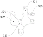
所述勾爪包括第一夹持爪、第二夹持爪、第一弹性件、齿条、推块、第二弹性件和拉环,所述第一夹持爪与所述夹持座相连接,所述第二夹持爪与所述第一夹持爪铰接,所述第一弹性件的两端分别与所述第一夹持爪和所述第二夹持爪相连接,所述齿条分别位于所述第一夹持爪和所述第二夹持爪内,所述推块的两端分别与所述第一夹持爪和所述第二夹持爪滑动连接,且与所述齿条相啮合,所述推块用于沿所述齿条朝向所述夹持座移动,以使所述第一夹持爪和所述第二夹持爪相互靠近,所述第二弹性件的两端分别与所述推块和所述第一夹持爪相连接,所述拉环安装在所述第一夹持爪的一侧,且与所述齿条相连接,所述拉环用于朝向所述夹持座移动,以驱动所述齿条与所述推块分离;The claw includes a first clamping claw, a second clamping claw, a first elastic member, a rack, a push block, a second elastic member and a pull ring, and the first clamping claw is in contact with the clamping seat. connected, the second clamping claw is hinged to the first clamping claw, the two ends of the first elastic member are respectively connected to the first clamping claw and the second clamping claw, and the The racks are respectively located in the first clamping claw and the second clamping claw, and the two ends of the push block are respectively slidably connected with the first clamping claw and the second clamping claw, and are connected with the The racks are engaged, and the push block is used to move toward the clamping seat along the rack, so that the first clamping claw and the second clamping claw are close to each other, and the second clamping claw is Both ends of the elastic member are respectively connected with the push block and the first clamping claw, the pull ring is installed on one side of the first clamping claw and connected with the rack, the The pull ring is used to move toward the clamping seat to drive the rack to separate from the push block;
所述夹持座上设置有第三伸缩动力件,所述第三伸缩动力件通过传动绳与所述拉环相连接,所述第三伸缩动力件与所述控制元件电连接,所述控制元件还用于:The clamping seat is provided with a third telescopic power part, the third telescopic power part is connected with the pull ring through a transmission rope, the third telescopic power part is electrically connected with the control element, and the control Components are also used in:
当所述第一夹持爪与所述第二夹持爪配合夹持所述待作业电线后,控制所述第三伸缩动力件伸缩,通过所述传动绳驱动所述拉环朝向所述夹持座移动。After the first clamping claw cooperates with the second clamping claw to clamp the wire to be operated, the third telescopic power part is controlled to expand and contract, and the pull ring is driven toward the clamp through the transmission rope. Seat moves.
可选地,所述夹持组件还包括第四伸缩动力件、第三旋转动力件和第二铰接轴,所述勾爪的数量为三个,所述勾爪沿所述夹持座等间隔设置,中间的所述勾爪通过所述第四伸缩动力件与所述夹持座相连接,所述第四伸缩动力件用于驱动所述勾爪朝向背离所述夹持座的方向移动,所述夹持座通过所述第二铰接轴与所述伸缩组件铰接,所述第三旋转动力件与所述夹持座驱动连接,所述第四伸缩动力件与所述第三旋转动力件均与所述控制元件电连接,所述控制元件还用于:Optionally, the clamping assembly further includes a fourth telescopic power member, a third rotating power member and a second hinge shaft, the number of the claws is three, and the claws are equally spaced along the clamping seat It is set that the hook in the middle is connected to the clamping seat through the fourth telescopic power part, and the fourth telescopic power part is used to drive the hook to move in a direction away from the clamping seat, The clamping seat is hinged to the telescopic assembly through the second hinge shaft, the third rotating power part is drivingly connected to the clamping seat, and the fourth telescopic power part is connected to the third rotating power part are electrically connected with the control element, and the control element is also used for:
当所述待作业电线为低压线时,控制所述第三旋转动力件驱动所述夹持座转动,所述勾爪与所述伸缩组件平行;When the electric wire to be operated is a low-voltage wire, control the third rotating power member to drive the clamping seat to rotate, and the claw is parallel to the telescopic assembly;
当所述待作业电线为高压线时,控制所述第三旋转动力件驱动所述夹持座转动,所述勾爪与所述伸缩组件垂直。When the electric wire to be operated is a high-voltage wire, the third rotating power member is controlled to drive the clamping seat to rotate, and the claw is perpendicular to the telescopic assembly.
可选地,所述夹持组件还包括第四旋转动力件和红外感应器,所述第四旋转动力件安装在所述伸缩组件上,且与所述夹持座驱动连接,用于驱动所述夹持座绕所述伸缩组件的轴线旋转,所述红外感应器安装在所述勾爪上,所述第四旋转动力件和所述红外感应器均与所述控制元件电连接,所述控制元件还用于:Optionally, the clamping assembly further includes a fourth rotating power member and an infrared sensor, the fourth rotating power member is installed on the telescoping assembly, and is drivingly connected with the clamping seat, and is used to drive the The clamping seat rotates around the axis of the telescopic assembly, the infrared sensor is installed on the claw, the fourth rotating power part and the infrared sensor are both electrically connected to the control element, the Control elements are also used for:
根据所述红外感应器判断所述勾爪是否对准所述待作业电线;According to the infrared sensor, it is judged whether the claw is aligned with the electric wire to be operated;
若是,驱动所述勾爪朝向所述待作业电线移动;If so, drive the hook to move towards the wire to be operated;
若否,调节所述勾爪。If not, adjust the dropout.
另一方面,本发明还提供一种旁路带电作业方法,应用于如上所述的旁路带电作业车载式机器人,所述旁路带电作业方法包括:On the other hand, the present invention also provides a bypass live working method, which is applied to the vehicle-mounted bypass live working robot described above, and the bypass live live working method includes:
当移动平台位于工作位置时,控制伸缩组件伸缩,驱动夹持组件朝向待作业电线移动;When the mobile platform is at the working position, the telescopic component is controlled to expand and contract, and the clamping component is driven to move towards the wire to be operated;
当所述夹持组件移动至所述待作业电线时,控制所述夹持组件夹持所述待作业电线,以使线缆与所述待作业电线搭接。When the clamping assembly moves to the electric wire to be operated, the clamping assembly is controlled to clamp the electric wire to be operated so that the cable overlaps the electric wire to be operated.
相对于现有技术,本发明的旁路带电作业方法的有益效果与如上所述的旁路带电作业车载式机器人的有益效果相同,在此不再赘述。Compared with the prior art, the beneficial effect of the bypass live working method of the present invention is the same as that of the vehicle-mounted robot for bypass live working described above, and will not be repeated here.
再一方面,本发明还提供一种车辆,包括如上所述的旁路带电作业车载式机器人和移动平台。In yet another aspect, the present invention also provides a vehicle, including the above-mentioned vehicle-mounted robot for bypass live work and a mobile platform.
相对于现有技术,本发明的车辆的有益效果与如上所述的旁路带电作业车载式机器人的有益效果相同,在此不再赘述。Compared with the prior art, the beneficial effect of the vehicle of the present invention is the same as that of the vehicle-mounted robot for bypassing live work as described above, and will not be repeated here.
附图说明Description of drawings
图1为本发明一实施例中旁路带电作业车载式机器人的结构示意图;Fig. 1 is a structural schematic diagram of a vehicle-mounted robot for bypass live work in an embodiment of the present invention;
图2为本发明一实施例中旁路带电作业车载式机器人的连接示意图;Fig. 2 is a connection schematic diagram of a vehicle-mounted robot for bypass live work in an embodiment of the present invention;
图3为图1中所示A的放大图;Fig. 3 is an enlarged view of A shown in Fig. 1;
图4为本发明一实施例中伸缩组件的结构示意图;Fig. 4 is a schematic structural diagram of the telescopic assembly in an embodiment of the present invention;
图5为图1中所述B的放大示意图;Fig. 5 is the enlarged schematic diagram of B described in Fig. 1;
图6为本发明一实施例中勾爪的结构示意图;Fig. 6 is a schematic structural view of the hook in an embodiment of the present invention;
图7为本发明一实施例中旁路带电作业方法的流程图。Fig. 7 is a flow chart of a method for bypass live working in an embodiment of the present invention.
附图标记说明:Explanation of reference signs:
1-支撑台;2-伸缩组件;21-伸缩套杆;3-夹持组件;31-夹持座;32-勾爪;321-第一夹持爪;322-第二夹持爪;323-第一弹性件;324-推块;325-拉环;33-第四伸缩动力件;34-第三旋转动力件;35-第二铰接轴;36-第四旋转动力件;5-移动平台;6-旋转组件;61-第一旋转动力件;62-第一伸缩动力件;63-旋转台;64-第一铰接轴。1-support platform; 2-telescopic component; 21-telescopic rod; 3-clamping component; 31-clamping seat; 32-hook; 321-first clamping claw; 322-second clamping claw; 323 -the first elastic part; 324-push block; 325-pull ring; 33-the fourth telescopic power part; 34-the third rotating power part; 35-the second hinge shaft; 36-the fourth rotating power part; 5-moving Platform; 6-rotating assembly; 61-first rotating power part; 62-first telescoping power part; 63-rotary table; 64-first hinged shaft.
具体实施方式detailed description
为使本发明的上述目的、特征和优点能够更为明显易懂,下面结合附图对本发明的具体实施例做详细的说明。In order to make the above objects, features and advantages of the present invention more comprehensible, specific embodiments of the present invention will be described in detail below in conjunction with the accompanying drawings.
需要说明的是,本文提供的坐标系XYZ中,X轴的正向代表右方,X轴的反向代表左方,Y轴的正向代表后方,Y轴的反向代表前方,Z轴的正向代表上方,Z轴的反向代表下方。同时,要说明的是,本发明的说明书和权利要求书及上述附图中的术语“第一”、“第二”等是用于区别类似的对象,而不必用于描述特定的顺序或先后次序。应该理解这样使用的数据在适当情况下可以互换,以便这里描述的本发明的实施例能够以除了在这里图示或描述的那些以外的顺序实施。It should be noted that in the coordinate system XYZ provided in this article, the positive direction of the X-axis represents the right, the reverse direction of the X-axis represents the left, the positive direction of the Y-axis represents the rear, the reverse direction of the Y-axis represents the front, and the reverse direction of the Z-axis represents the front. The positive direction represents the upward direction, and the reverse direction of the Z axis represents the downward direction. At the same time, it should be noted that the terms "first" and "second" in the description and claims of the present invention and the above drawings are used to distinguish similar objects, and not necessarily used to describe a specific order or sequence order. It is to be understood that the data so used are interchangeable under appropriate circumstances such that the embodiments of the invention described herein can be practiced in sequences other than those illustrated or described herein.
为了解决上述问题,一方面,本发明一实施例提供一种旁路带电作业车载式机器人,包括:支撑台1,支撑台1用于安装在移动平台5上;伸缩组件2,伸缩组件2安装在支撑台1上;夹持组件3,夹持组件3与伸缩组件2驱动连接,夹持组件3用于连接线缆;控制元件,控制元件分别与伸缩组件2和夹持组件3电连接,控制元件用于:当移动平台5位于工作位置时,控制伸缩组件2伸缩,驱动夹持组件3朝向待作业电线移动;当夹持组件3移动至待作业电线时,控制夹持组件3夹持待作业电线,以使线缆与待作业电线搭接。In order to solve the above problems, on the one hand, an embodiment of the present invention provides a vehicle-mounted robot for bypass live work, including: a
如图1和图2所示,在本实施例中,设置支撑台1用于对整个旁路带电作业车载式机器人进行支撑,保证工作的稳定性,支撑台1可安装在移动平台5上,方便进行移动,在某一区域需要进行旁路带电作业时,可快速移动至该区域,有效提升作业效率。As shown in Figures 1 and 2, in this embodiment, a
同时,在支撑台1上设置伸缩组件2,伸缩组件2的驱动端连接有夹持组件3,在进行旁路带电作业时,将需要搭接的线缆与夹持组件3相连接,伸缩组件2驱动夹持组件3朝向待作业电线移动,在夹持组件3移动至待作业电线时,驱动夹持组件3夹持待作业电线,完成线缆与待作业电线的搭接,当然,在旁路带电作业完成后,可驱动夹持组件3与待作业电线脱离,实现线缆与待作业电线的脱离;At the same time, a
这样,通过伸缩组件实现夹持组件朝向待作业电线的移动,从而可实现线缆的稳定移动,同时通过夹持组件可与待作业电线稳定连接,从而可实现线缆与待作业电线的稳定搭接,此外,还设置控制元件与各个工作组件电连接,在进行旁路带电作业时,可通过控制元件对各个工作组件进行控制,实现线缆的自动提升和搭接,无需人工对线缆进行拖拽和搭接,作业速度较快,安全性较高,有效节省了人力和保证了作业安全性,可有效提升旁路带电作业的效率和安全性。In this way, the movement of the clamping component towards the wire to be operated is realized through the telescopic component, so that the stable movement of the cable can be realized, and at the same time, the stable connection with the wire to be operated can be realized through the clamping component, so that the stable lapping of the cable and the wire to be operated can be realized. In addition, the control element is also set to be electrically connected to each working component. When performing bypass live work, each working component can be controlled through the control element to realize automatic lifting and lapping of the cable, without manual adjustment of the cable. Dragging and lapping, the operation speed is faster and the safety is higher, which effectively saves manpower and ensures operation safety, and can effectively improve the efficiency and safety of bypass live work.
需要说明的是,在本实施例中,控制元件可为PLC控制器,在本发明的其他实施例中,还可以设置远程通讯元件和移动控制终端,通过控制元件、远程通讯元件以及移动控制终端,可使得作业人员对旁路带电作业车载式机器人的作业进行远程移动式控制,进一步提升作业的便捷性。It should be noted that, in this embodiment, the control element can be a PLC controller, and in other embodiments of the present invention, a remote communication element and a mobile control terminal can also be set, and the control element, the remote communication element, and the mobile control terminal , allowing the operator to perform remote mobile control on the operation of the vehicle-mounted robot for bypass live work, further improving the convenience of the operation.
可选地,旁路带电作业车载式机器人还包括旋转组件6,旋转组件6安装在支撑台1上,且与伸缩组件2驱动连接,旋转组件6与控制元件电连接,控制元件还用于:在移动平台5位于工作位置后,控制伸缩组件2伸缩前,控制旋转组件6旋转,以驱动伸缩组件2对准待作业电线。Optionally, the vehicle-mounted robot for bypass live work also includes a
为了进一步提升作业效率和作业质量,如图1和图2所示,在本实施例中,设置旋转组件6,将旋转组件6安装在支撑台1上,且旋转组件6与伸缩组件2驱动连接,以及与控制元件电连接,这样,在需要进行旁路带电作业时,可控制旋转组件6输出旋转力,从而驱动伸缩组件2旋转,使得伸缩组件2的伸缩方向与待作业电线对应,即伸缩组件2对准待作业电线,在伸缩组件2驱动夹持组件3伸长时,可使得夹持组件3准确的朝向待作业电线移动,从而达到精准夹持和搭接的目的,提升作业的效率和质量。In order to further improve the working efficiency and working quality, as shown in Figure 1 and Figure 2, in this embodiment, a
可选地,旋转组件6包括第一旋转动力件61、第一伸缩动力件62、旋转台63和第一铰接轴64,第一旋转动力件61竖直安装在支撑台1上,且与旋转台63驱动连接,第一伸缩动力件62的两端分别与支撑台1和伸缩组件2铰接,旋转台63通过第一铰接轴64与伸缩组件2铰接,第一铰接轴64沿水平方向设置,第一旋转动力件61和第一伸缩动力件62均与控制元件电连接,控制元件还用于:开启第一旋转动力件61,驱动旋转台63绕竖直轴线旋转;开启第一伸缩动力件62,控制第一伸缩动力件62伸缩,以驱动伸缩组件2绕水平轴线旋转。Optionally, the rotating
需要说明的是,在本实施例中,如图1所示,水平方向位于XY平面,水平轴线即为位于XY平面的轴线,竖直方向为Z轴方向,竖直轴线即为Z轴。It should be noted that, in this embodiment, as shown in FIG. 1 , the horizontal direction is on the XY plane, the horizontal axis is the axis on the XY plane, the vertical direction is the Z axis, and the vertical axis is the Z axis.
如图1和图3所示,在本实施例中,设置第一旋转动力件61、第一伸缩动力件62、旋转台63和第一铰接轴64组成旋转组件6,具体地,将第一旋转动力件61设置在支撑台1上,在将旋转台63与第一旋转动力件61驱动连接,旋转台63通过沿X轴方向设置的第一铰接轴64与伸缩组件2铰接,第一伸缩动力件62的两端分别与旋转台63和伸缩组件2铰接,且第一旋转动力件61和第一伸缩动力件62均与控制元件电连接。As shown in Figures 1 and 3, in this embodiment, the first
这样,在进行旁路带电作业时,为了保证伸缩组件2的伸缩方向与待作业电线相对应,可通过第一旋转动力件61输出旋转力,来驱动旋转台63绕Z轴旋转,从而使得伸缩组件2与待作业电线位于同一竖直平面上,再通过第一伸缩动力件62输出伸缩力,第一伸缩动力件62的两端分别相对于伸缩组件2和旋转台63旋转,由于旋转台63保持不动,从而第一伸缩动力件62可驱动伸缩组件2绕第一铰接轴64旋转,调节伸缩组件2与XY平面的角度,从而使得伸缩组件2与待作业电线相对应,方便后续伸缩组件2伸缩,驱动夹持组件3精准夹持待作业电线。In this way, in order to ensure that the expansion and contraction direction of the expansion and
需要说明的是,在本实施例中,第一旋转动力件61为伺服电机,第一伸缩动力件62为伺服电缸。It should be noted that, in this embodiment, the first
可选地,伸缩组件2包括伸缩套杆21和第二伸缩动力件,伸缩套杆21的两端分别与支撑台1和夹持组件3相连接,第二伸缩动力件安装在伸缩套杆21内,且与伸缩套杆21的端部驱动连接,第二伸缩动力件与控制元件电连接,控制元件还用于:开启第二伸缩动力件,控制第二伸缩动力件驱动伸缩套杆21伸缩。Optionally, the
如图1和图4所示,在本实施例中,设置伸缩套杆21和第二伸缩动力件组成伸缩组件2,伸缩套杆21的两端分别与支撑台1和夹持组件3相连接,第二伸缩动力件设置在伸缩套杆21内,且与伸缩套杆21的端部驱动连接,第二伸缩动力件还与控制元件电连接。As shown in Figure 1 and Figure 4, in this embodiment, a
这样,在需要进行伸缩时,控制第二伸缩动力件输出伸缩力,从而驱动伸缩套杆21伸长或缩短,达到驱动夹持组件3朝向和背离待作业电线的目的。In this way, when stretching is required, the second stretching power member is controlled to output stretching force, thereby driving the stretching
需要说明的是,在本实施例中,伸缩套杆21由多个截面积依次减小的两端开口的中空件依次连接组成,通过相邻中空件之间的相互移动,实现整个伸缩套杆21的伸缩,其中,在本实施例中,中空件为两端开口的长方体中空结构。It should be noted that, in this embodiment, the
需要说明的是,在本实施例中,第二伸缩动力件为伺服电缸。It should be noted that, in this embodiment, the second telescopic power member is a servo electric cylinder.
可选地,旁路带电作业车载式机器人还包括线缆收放组件,线缆收放组件包括线缆收放绞盘和第二旋转动力件,第二旋转动力件与线缆收放绞盘驱动连接,线缆收放绞盘安装在支撑台1上且用于放置线缆,第二旋转动力件与控制元件电连接,控制元件还用于:当伸缩组件2伸缩时,控制第二旋转动力件驱动线缆收放绞盘旋转,且线缆收放绞盘的旋转线速度与伸缩组件2的伸缩移动速度相同。Optionally, the vehicle-mounted robot for bypass live work also includes a cable retracting assembly, the cable retracting assembly includes a cable retracting winch and a second rotating power member, and the second rotating power member is drivingly connected to the cable retracting winch , the cable retractable winch is installed on the
为了保证线缆的稳定收放,防止线缆出现损伤,在本实施例中,还设置线缆收放绞盘和第二旋转动力件组成线缆收放组件,线缆收放绞盘设置在支撑台1上,其上缠绕线缆,第二旋转动力件与线缆收放绞盘驱动连接,且与控制元件电连接,这样,在伸缩组件2伸缩的同时,通过第二旋转动力件驱动线缆收放绞盘旋转,使得线缆的伸长和收回速度与伸缩组件2的伸缩速度相一致,保证线缆使用的稳定性,防止外力对线缆造成损伤。In order to ensure stable cable retraction and prevent cable damage, in this embodiment, a cable retractable winch and a second rotating power member are also set to form a cable retractable assembly, and the cable retractable winch is set on the
需要说明的是,在本实施例中,第二旋转动力件为伺服电机。It should be noted that, in this embodiment, the second rotating power member is a servo motor.
可选地,夹持组件3包括夹持座31和多个勾爪32,勾爪32间隔设置在夹持座31上,夹持座31安装在伸缩组件2的端部;勾爪32包括第一夹持爪321、第二夹持爪322、第一弹性件323、齿条、推块324、第二弹性件和拉环325,第一夹持爪321与夹持座31相连接,第二夹持爪322与第一夹持爪321铰接,第一弹性件323的两端分别与第一夹持爪321和第二夹持爪322相连接,齿条分别位于第一夹持爪321和第二夹持爪322内,推块324的两端分别与第一夹持爪321和第二夹持爪322滑动连接,且与齿条相啮合,推块324用于沿齿条朝向夹持座31移动,以使第一夹持爪321和第二夹持爪322相互靠近,第二弹性件的两端分别与推块324和第一夹持爪321相连接,拉环325安装在第一夹持爪321的一侧,且与齿条相连接,拉环325用于朝向夹持座31移动,以驱动齿条与推块324分离;夹持座31上设置有第三伸缩动力件,第三伸缩动力件通过传动绳与拉环325相连接,第三伸缩动力件与控制元件电连接,控制元件还用于:当第一夹持爪321与第二夹持爪322配合夹持待作业电线后,控制第三伸缩动力件伸缩,通过传动绳驱动拉环325朝向夹持座31移动。Optionally, the clamping
为了保证线缆与待作业电线的稳定搭接,如图1和图5所示,在本实施例中,设置夹持座31和多个勾爪32组成夹持组件3,夹持座31安装在伸缩组件2的端部,勾爪32间隔设置在夹持座31上,在进行旁路带电作业时,根据待作业电线的数量,使用相同数量的勾爪32,一一与线缆连接,并通过伸缩组件2伸缩,使得勾爪32夹持在待作业电线上,实现线缆和待作业电线的稳定搭接。In order to ensure the stable overlapping of cables and wires to be operated, as shown in Figure 1 and Figure 5, in this embodiment, a clamping
具体地,如图5所示,勾爪32包括第一夹持爪321、第二夹持爪322、第一弹性件323、齿条、推块324、第二弹性件和拉环325,其中,第一夹持爪321和第二夹持爪322铰接,组成勾爪32的主体结构,第一夹持爪321与夹持座31相连接,在第一夹持爪321和第二夹持爪322内均设置齿条,将第一弹性件323与第一夹持爪321和第二夹持爪322相连接,将推块324滑动设置在第一夹持爪321和第二夹持爪322之间,且推块324的端部与齿条相啮合,这样,在夹持座31带动第勾爪32到达待作业电线时,待作业电线位于第一夹持爪321和第二夹持爪322之间,随着伸缩组件2的继续伸长,待作业电线与推块324抵接,推动推块324朝向夹持座31的方向移动,推块324沿齿条移动,第一夹持爪321和第二夹持爪322之间的距离缩短,第一弹性件323原始处于拉长状态,在第一弹性件323的复位弹力的作用下,第一夹持爪321和第二夹持爪322实现对待作业电线的稳定夹持,保证线缆与待作业电线的稳定搭接;Specifically, as shown in FIG. 5 , the
同时,为了方便勾爪32与待作业电线脱离,将第二弹性件的两端分别与推块324和第一夹持爪321相连接,将拉环325与齿条相连接,并在夹持座31上设置有第三伸缩动力件,第三伸缩动力件通过传动绳与拉环325相连接,第三伸缩动力件与控制元件电连接,这样,通过控制第三伸缩动力件输出伸缩力,可驱动传动绳拉着拉环325朝向夹持座31移动,从而带动齿条与推块324分离,第二弹性件此时处于压缩状态,在第二弹性件的复位弹力作用下,推块324朝向背离夹持座31的方向移动,使得第一夹持爪321和第二夹持爪322相互分离,勾爪32与待作业电线脱离。Simultaneously, in order to facilitate the detachment of the
需要说明的是,在本实施例中,第三伸缩动力件为伺服电缸,第一弹性件和第二弹性件均为强力弹簧。It should be noted that, in this embodiment, the third telescopic power member is a servo electric cylinder, and both the first elastic member and the second elastic member are powerful springs.
可选地,夹持组件3还包括第四伸缩动力件33、第三旋转动力件34和第二铰接轴35,勾爪32的数量为三个,勾爪32沿夹持座31等间隔设置,中间的勾爪32通过第四伸缩动力件33与夹持座31相连接,第四伸缩动力件33用于驱动勾爪32朝向背离夹持座31的方向移动,夹持座31通过第二铰接轴35与伸缩组件2铰接,第三旋转动力件34与夹持座31驱动连接,第四伸缩动力件33与第三旋转动力件34均与控制元件电连接,控制元件还用于:当待作业电线为低压线时,控制第三旋转动力件34驱动夹持座31转动,勾爪32与伸缩组件2平行;当待作业电线为高压线时,控制第三旋转动力件34驱动夹持座31转动,勾爪32与伸缩组件2垂直。Optionally, the clamping
由于待作业电线多为三条线,且沿等腰三角形三个顶点排布,因此,在本实施例中,如图5所示,将勾爪32设置为三个,沿夹持座31等间隔设置,中间的勾爪32通过第四伸缩动力件33与夹持座31相连接,第四伸缩动力件33与控制元件电连接,这样,在进行待作业电线的夹持时,通过第四伸缩动力件33驱动中间的勾爪32移动,满足对呈等腰三角形设置的待作业电线的夹持。Since the electric wires to be operated are mostly three lines, and are arranged along the three vertices of an isosceles triangle, in this embodiment, as shown in Figure 5, three
此外,考虑到高压线一般呈竖直排布,低压线呈水平排布,为了方便勾爪32对待作业电线的夹持,将夹持座31通过第三旋转动力件34与伸缩组件2相连接,第三旋转动力件34与控制元件电连接,当待作业电线为低压线时,控制第三旋转动力件34驱动夹持座31旋转,使得勾爪32与伸缩组件2平行,方便对低压线进行夹持,当待作业电线为高压线时,控制第三旋转动力件34驱动夹持座31旋转,使得勾爪32与伸缩组件2垂直,方便对高压线进行夹持。In addition, considering that the high-voltage wires are generally arranged vertically and the low-voltage wires are arranged horizontally, in order to facilitate the
需要说明的是,在本实施例中,第四伸缩动力件33为伺服电缸,第三旋转动力件34为伺服电机。It should be noted that, in this embodiment, the fourth
可选地,夹持组件3还包括第四旋转动力件36和红外感应器,第四旋转动力件36安装在伸缩组件2上,且与夹持座31驱动连接,用于驱动夹持座31绕伸缩组件2的轴线旋转,红外感应器安装在勾爪32上,第四旋转动力件36和红外感应器均与控制元件电连接,控制元件还用于:根据红外感应器判断勾爪32是否对准待作业电线;若是,驱动勾爪32朝向待作业电线移动;若否,调节勾爪32。Optionally, the clamping
为了进一步提升勾爪32夹持的准确度,在本实施例中,如图5所示,还设置了第四旋转动力件36,第四旋转动力件36设置在夹持座31上且通过齿轮与伸缩组件2端部的传动齿轮相啮合,第四旋转动力件36与控制元件电连接,在需要对夹持座31上的勾爪32与各个待作业电线的对应关系进行调节时,可控制第四旋转动力件36驱动齿轮旋转,齿轮绕传动齿轮的周向转动,从而实现夹持座31绕伸缩组件2的轴线的转动,调整勾爪32的位置,进行准确对应。In order to further improve the clamping accuracy of the
此外,还在勾爪32上设置了与控制元件电连接的红外感应器,当红外感应器感应到勾爪32对准待作业电线时,可控制勾爪32朝向待作业电线移动,当未对准时,可调节勾爪32。In addition, an infrared sensor electrically connected to the control element is also provided on the
需要说明的是,在本实施例中,第四旋转动力件36为伺服电机。It should be noted that, in this embodiment, the fourth
另一方面,本发明一实施例还提供一种旁路带电作业方法,应用于上述的旁路带电作业车载式机器人,旁路带电作业方法包括:当移动平台5位于工作位置时,控制伸缩组件2伸缩,驱动夹持组件3朝向待作业电线移动;当夹持组件3移动至待作业电线时,控制夹持组件3夹持待作业电线,以使线缆与待作业电线搭接。On the other hand, an embodiment of the present invention also provides a bypass live working method, which is applied to the above-mentioned bypass live working vehicle-mounted robot. The bypass live working method includes: when the
如图7的S1和S2所示,在本实施例中,旁路带电作业方法的技术效果与上述的旁路带电作业车载机器人的技术效果相类似,在此不再赘述。As shown in S1 and S2 of FIG. 7 , in this embodiment, the technical effect of the bypass live working method is similar to the technical effect of the above-mentioned bypass live working vehicle-mounted robot, and will not be repeated here.
再一方面,本发明一实施例还提供一种车辆,包括上述的旁路带电作业车载机器人和移动平台5。In yet another aspect, an embodiment of the present invention also provides a vehicle, including the above-mentioned vehicle-mounted robot for bypass live work and the
如图1至图6所示,在本实施例中,车辆的技术效果与上述的旁路带电作业车载机器人的技术效果相类似,在此不再赘述。As shown in Fig. 1 to Fig. 6, in this embodiment, the technical effect of the vehicle is similar to that of the above-mentioned vehicle-mounted robot for bypass live work, and will not be repeated here.
虽然本公开披露如上,但本公开的保护范围并非仅限于此。本领域技术人员在不脱离本公开的精神和范围的前提下,可进行各种变更与修改,这些变更与修改均将落入本发明的保护范围。Although the present disclosure is disclosed as above, the protection scope of the present disclosure is not limited thereto. Those skilled in the art can make various changes and modifications without departing from the spirit and scope of the present disclosure, and these changes and modifications will all fall within the protection scope of the present invention.
Claims (8)
Priority Applications (1)
| Application Number | Priority Date | Filing Date | Title |
|---|---|---|---|
| CN202211100725.9A CN115189298B (en) | 2022-09-09 | 2022-09-09 | Vehicle-mounted robot, method and vehicle for bypass live working |
Applications Claiming Priority (1)
| Application Number | Priority Date | Filing Date | Title |
|---|---|---|---|
| CN202211100725.9A CN115189298B (en) | 2022-09-09 | 2022-09-09 | Vehicle-mounted robot, method and vehicle for bypass live working |
Publications (2)
| Publication Number | Publication Date |
|---|---|
| CN115189298A CN115189298A (en) | 2022-10-14 |
| CN115189298B true CN115189298B (en) | 2022-12-20 |
Family
ID=83524729
Family Applications (1)
| Application Number | Title | Priority Date | Filing Date |
|---|---|---|---|
| CN202211100725.9A Active CN115189298B (en) | 2022-09-09 | 2022-09-09 | Vehicle-mounted robot, method and vehicle for bypass live working |
Country Status (1)
| Country | Link |
|---|---|
| CN (1) | CN115189298B (en) |
Citations (13)
| Publication number | Priority date | Publication date | Assignee | Title |
|---|---|---|---|---|
| US5206984A (en) * | 1991-06-20 | 1993-05-04 | Kokusai Keisokuki Kabushiki Kaisha | Apparatus for mounting a balance weight on a tire wheel |
| JP2012023890A (en) * | 2010-07-15 | 2012-02-02 | Chugoku Electric Power Co Inc:The | Hot line work robot for special high voltage |
| CN103762520A (en) * | 2014-02-21 | 2014-04-30 | 国网湖南省电力公司带电作业中心 | Electric mobile platform for bypass work of 10 KV distribution line |
| CN106956275A (en) * | 2017-04-03 | 2017-07-18 | 徐荣华 | A kind of cable mounting robot |
| CN107053188A (en) * | 2016-12-09 | 2017-08-18 | 南京理工大学 | A kind of hot line robot branch connects gage lap method |
| CN206869862U (en) * | 2017-07-13 | 2018-01-12 | 福建(泉州)哈工大工程技术研究院 | A kind of robot of livewire work |
| CN109366453A (en) * | 2018-10-24 | 2019-02-22 | 国网江苏省电力有限公司徐州供电分公司 | A dual-arm robot for live work on power distribution lines and its control method |
| CN210053133U (en) * | 2019-06-03 | 2020-02-11 | 湖南工艺美术职业学院 | Computer network strutting arrangement |
| CN111702786A (en) * | 2020-08-20 | 2020-09-25 | 天津滨电电力工程有限公司 | A special assembled lead bracket for live working robots |
| CN214755178U (en) * | 2021-04-29 | 2021-11-16 | 淳安县电力实业有限公司 | Bypass cable and electrified wire connecting device |
| CN113681566A (en) * | 2021-09-10 | 2021-11-23 | 广东电网有限责任公司广州供电局 | Control method and controller of drainage wire operation robot |
| CN215797542U (en) * | 2021-09-29 | 2022-02-11 | 国网四川省电力公司成都供电公司 | Lifting type bypass cable discharging device and bypass operation vehicle |
| CN216883947U (en) * | 2021-11-26 | 2022-07-05 | 浙江大有实业有限公司带电作业分公司 | Single-arm man-machine cooperation distribution network live working equipment |
Family Cites Families (1)
| Publication number | Priority date | Publication date | Assignee | Title |
|---|---|---|---|---|
| CN111555203A (en) * | 2020-06-04 | 2020-08-18 | 上海机器人产业技术研究院有限公司 | Double-arm cooperative high-voltage doubling robot |
-
2022
- 2022-09-09 CN CN202211100725.9A patent/CN115189298B/en active Active
Patent Citations (13)
| Publication number | Priority date | Publication date | Assignee | Title |
|---|---|---|---|---|
| US5206984A (en) * | 1991-06-20 | 1993-05-04 | Kokusai Keisokuki Kabushiki Kaisha | Apparatus for mounting a balance weight on a tire wheel |
| JP2012023890A (en) * | 2010-07-15 | 2012-02-02 | Chugoku Electric Power Co Inc:The | Hot line work robot for special high voltage |
| CN103762520A (en) * | 2014-02-21 | 2014-04-30 | 国网湖南省电力公司带电作业中心 | Electric mobile platform for bypass work of 10 KV distribution line |
| CN107053188A (en) * | 2016-12-09 | 2017-08-18 | 南京理工大学 | A kind of hot line robot branch connects gage lap method |
| CN106956275A (en) * | 2017-04-03 | 2017-07-18 | 徐荣华 | A kind of cable mounting robot |
| CN206869862U (en) * | 2017-07-13 | 2018-01-12 | 福建(泉州)哈工大工程技术研究院 | A kind of robot of livewire work |
| CN109366453A (en) * | 2018-10-24 | 2019-02-22 | 国网江苏省电力有限公司徐州供电分公司 | A dual-arm robot for live work on power distribution lines and its control method |
| CN210053133U (en) * | 2019-06-03 | 2020-02-11 | 湖南工艺美术职业学院 | Computer network strutting arrangement |
| CN111702786A (en) * | 2020-08-20 | 2020-09-25 | 天津滨电电力工程有限公司 | A special assembled lead bracket for live working robots |
| CN214755178U (en) * | 2021-04-29 | 2021-11-16 | 淳安县电力实业有限公司 | Bypass cable and electrified wire connecting device |
| CN113681566A (en) * | 2021-09-10 | 2021-11-23 | 广东电网有限责任公司广州供电局 | Control method and controller of drainage wire operation robot |
| CN215797542U (en) * | 2021-09-29 | 2022-02-11 | 国网四川省电力公司成都供电公司 | Lifting type bypass cable discharging device and bypass operation vehicle |
| CN216883947U (en) * | 2021-11-26 | 2022-07-05 | 浙江大有实业有限公司带电作业分公司 | Single-arm man-machine cooperation distribution network live working equipment |
Also Published As
| Publication number | Publication date |
|---|---|
| CN115189298A (en) | 2022-10-14 |
Similar Documents
| Publication | Publication Date | Title |
|---|---|---|
| CN109904789B (en) | A ground wire hooking device | |
| CN110601081A (en) | Distribution network live lead wire breaking and connecting system and method thereof | |
| CN110040628B (en) | Submersible vehicle retracting and releasing method | |
| CN210838698U (en) | Operation robot system for distribution network electrified disconnection and connection of lead wire | |
| CN110601082A (en) | Distribution network live disconnection and connection method and corresponding system thereof | |
| CN105437205A (en) | Mechanical hand for loading and unloading column-shaped objects | |
| CN217572947U (en) | Mechanical arm machining turnover device | |
| CN108011325B (en) | Automatic long wire harness pipe penetrating machine and method | |
| CN115189298B (en) | Vehicle-mounted robot, method and vehicle for bypass live working | |
| CN114834601B (en) | Automatic laying and recycling device for submersible | |
| CN116728376A (en) | A mobile grabbing robot | |
| CN117498219A (en) | A kind of double-split conductor robot for transmission lines and its on-line and off-line methods | |
| KR101554947B1 (en) | Electric cable installation robot and cable installation using the same | |
| CN214298980U (en) | Material removes hoist device for electric power | |
| CN113410798B (en) | A quick construction robot of electric power cable for epidemic prevention is emergent | |
| CN206286305U (en) | A kind of haulage equipment and the cleaning device with the haulage equipment | |
| CN211103999U (en) | A pneumatic manipulator arm | |
| CN110788554B (en) | Adjustable tooling clamp for welding automobile parts | |
| CN202622514U (en) | Docking mechanism for automatic crystal blank grinding and polishing system | |
| JP2744111B2 (en) | Cable laying manipulator | |
| CN112952531A (en) | Wire clamping device and core wire positioning equipment | |
| CN112591625A (en) | Material removes hoist device for electric power | |
| CN214526705U (en) | Mechanical manufacturing grabbing device | |
| CN219259154U (en) | Horizontal winding machine for cables | |
| CN112456401A (en) | Power transmission and transformation circuit installation mobile device |
Legal Events
| Date | Code | Title | Description |
|---|---|---|---|
| PB01 | Publication | ||
| PB01 | Publication | ||
| SE01 | Entry into force of request for substantive examination | ||
| SE01 | Entry into force of request for substantive examination | ||
| GR01 | Patent grant | ||
| GR01 | Patent grant |