CN115135929A - Oxygen flat flame burner and block assembly - Google Patents
Oxygen flat flame burner and block assembly Download PDFInfo
- Publication number
- CN115135929A CN115135929A CN202080096355.9A CN202080096355A CN115135929A CN 115135929 A CN115135929 A CN 115135929A CN 202080096355 A CN202080096355 A CN 202080096355A CN 115135929 A CN115135929 A CN 115135929A
- Authority
- CN
- China
- Prior art keywords
- block
- gas
- flame burner
- flat flame
- orifice
- Prior art date
- Legal status (The legal status is an assumption and is not a legal conclusion. Google has not performed a legal analysis and makes no representation as to the accuracy of the status listed.)
- Pending
Links
Images


Classifications
-
- F—MECHANICAL ENGINEERING; LIGHTING; HEATING; WEAPONS; BLASTING
- F23—COMBUSTION APPARATUS; COMBUSTION PROCESSES
- F23D—BURNERS
- F23D14/00—Burners for combustion of a gas, e.g. of a gas stored under pressure as a liquid
- F23D14/20—Non-premix gas burners, i.e. in which gaseous fuel is mixed with combustion air on arrival at the combustion zone
- F23D14/22—Non-premix gas burners, i.e. in which gaseous fuel is mixed with combustion air on arrival at the combustion zone with separate air and gas feed ducts, e.g. with ducts running parallel or crossing each other
-
- F—MECHANICAL ENGINEERING; LIGHTING; HEATING; WEAPONS; BLASTING
- F23—COMBUSTION APPARATUS; COMBUSTION PROCESSES
- F23C—METHODS OR APPARATUS FOR COMBUSTION USING FLUID FUEL OR SOLID FUEL SUSPENDED IN A CARRIER GAS OR AIR
- F23C6/00—Combustion apparatus characterised by the combination of two or more combustion chambers or combustion zones, e.g. for staged combustion
- F23C6/04—Combustion apparatus characterised by the combination of two or more combustion chambers or combustion zones, e.g. for staged combustion in series connection
- F23C6/045—Combustion apparatus characterised by the combination of two or more combustion chambers or combustion zones, e.g. for staged combustion in series connection with staged combustion in a single enclosure
-
- F—MECHANICAL ENGINEERING; LIGHTING; HEATING; WEAPONS; BLASTING
- F23—COMBUSTION APPARATUS; COMBUSTION PROCESSES
- F23D—BURNERS
- F23D14/00—Burners for combustion of a gas, e.g. of a gas stored under pressure as a liquid
- F23D14/32—Burners for combustion of a gas, e.g. of a gas stored under pressure as a liquid using a mixture of gaseous fuel and pure oxygen or oxygen-enriched air
-
- F—MECHANICAL ENGINEERING; LIGHTING; HEATING; WEAPONS; BLASTING
- F23—COMBUSTION APPARATUS; COMBUSTION PROCESSES
- F23M—CASINGS, LININGS, WALLS OR DOORS SPECIALLY ADAPTED FOR COMBUSTION CHAMBERS, e.g. FIREBRIDGES; DEVICES FOR DEFLECTING AIR, FLAMES OR COMBUSTION PRODUCTS IN COMBUSTION CHAMBERS; SAFETY ARRANGEMENTS SPECIALLY ADAPTED FOR COMBUSTION APPARATUS; DETAILS OF COMBUSTION CHAMBERS, NOT OTHERWISE PROVIDED FOR
- F23M5/00—Casings; Linings; Walls
- F23M5/02—Casings; Linings; Walls characterised by the shape of the bricks or blocks used
- F23M5/025—Casings; Linings; Walls characterised by the shape of the bricks or blocks used specially adapted for burner openings
-
- F—MECHANICAL ENGINEERING; LIGHTING; HEATING; WEAPONS; BLASTING
- F23—COMBUSTION APPARATUS; COMBUSTION PROCESSES
- F23D—BURNERS
- F23D2900/00—Special features of, or arrangements for burners using fluid fuels or solid fuels suspended in a carrier gas
- F23D2900/14—Special features of gas burners
- F23D2900/14641—Special features of gas burners with gas distribution manifolds or bars provided with a plurality of nozzles
Landscapes
- Engineering & Computer Science (AREA)
- Chemical & Material Sciences (AREA)
- Combustion & Propulsion (AREA)
- Mechanical Engineering (AREA)
- General Engineering & Computer Science (AREA)
- Gas Burners (AREA)
- Air Supply (AREA)
Abstract
A block and burner assembly includes a flat flame burner subassembly including a flat flame burner body in fluid communication with a gas source. The flat flame burner body includes a gas inlet in fluid communication with a gas source and a gas nozzle, and a fuel inlet in fluid communication with a fuel nozzle, wherein the gas nozzle is arranged to at least partially surround the fuel nozzle. The block and burner assembly includes a flat flame burner block arranged to receive at least a portion of a fuel nozzle and at least a portion of a gas nozzle, a staging injector subassembly in fluid communication with a gas source, and a staging injector block connected to the flat flame burner block and arranged to receive at least a portion of the staging injector subassembly, wherein the flat flame burner block and the staging injector block are separable.
Description
Technical Field
The present disclosure relates generally to gas burners and, more particularly, to a flat flame burner and a burner block assembly.
Background
Oxy-fuel combustion is a combustion fuel process that uses oxygen instead of air as the primary oxidant. The use of oxy-fuel combustion can reduce harmful environmental emissions because the nitrogen component of the air oxidant is eliminated, thereby reducing nitrogen oxide emissions and reducing fuel consumption.
In addition, gas burner assemblies are typically designed in conjunction with a burner block to help dissipate the heat generated by the combustion of the burner. Staged burner assemblies (e.g., gas burner assemblies designed to inject additional oxidant multiple times after ignition) are designed to work in conjunction with blocks that allow for the addition of a separate additional gas stream to the resulting combustion. In contrast, gas burner assemblies that are not designed to use additional oxidant after ignition typically utilize burner blocks that do not allow for the addition of additional staging gas to the combustion. Whether or not the burner block is designed to accept a staged burner system, the burner block is made of a material that is highly susceptible to cracking due to repeated thermal expansion.
Disclosure of Invention
The present disclosure relates generally to a block and burner assembly arranged to produce a flat flame and allow flexible adaptation between applications requiring staged or non-staged combustion. The block and burner assembly includes a flat flame burner subassembly having a gas nozzle arranged to extend a first distance from a body of the subassembly and a fuel nozzle arranged to extend a second distance from the body of the subassembly, wherein the first distance is less than or equal to the second distance. This nozzle arrangement helps to prevent backfiring and reduces the operating temperature of the subassembly. Further, the block and combustor assembly described herein allows for adaptive placement of the combustor block for different applications and allows for modular replacement and/or repair of separable combustor blocks. Further, in a staged configuration, the block and burner assembly includes a staged injector subassembly secured to the staged injector block, wherein the staged injector block includes a plurality of gas passages operably arranged to more effectively distribute a staged gas flow from the staged injector subassembly to combustion produced by the flat flame burner subassembly.
In one example, a block and burner assembly is provided that includes a flat flame burner subassembly including a flat flame burner body in fluid communication with a gas source. The flat flame burner body includes a gas inlet in fluid communication with a gas source and a gas nozzle, and a fuel inlet in fluid communication with a fuel nozzle, wherein the gas nozzle is arranged to at least partially surround the fuel nozzle. Additionally, the block and burner assembly includes a flat flame burner block arranged to receive at least a portion of a fuel nozzle and at least a portion of a gas nozzle, a staging injector subassembly in fluid communication with a gas source, and a staging injector block connected to the flat flame burner block and arranged to receive at least a portion of the staging injector subassembly, wherein the flat flame burner block and the staging injector block are separable.
In one aspect, the staging injector block is connected to a top side or a bottom side of the flat flame burner block.
In one aspect, the block and burner assembly further comprises a bracket arranged to secure the staged injector block to the flat flame burner block.
In one aspect, the gas nozzles are arranged to taper from a first width and a first height to a second width and a second height, wherein the first width is less than the second width and the first height is greater than the second height.
In one aspect, the fuel nozzle is arranged to taper from a third width and a third height to a fourth width and a fourth height, wherein the third width is less than the fourth width and the third height is greater than the fourth height.
In one aspect, the gas nozzle is arranged to protrude from the flat flame burner body in a first direction a first distance and the fuel nozzle is arranged to protrude from the flat flame burner body in the first direction a second distance, wherein the first distance is equal to the second distance, or wherein the first distance is less than the second distance.
In one aspect, the staging injector block includes a plurality of gas passages, wherein each of the plurality of gas passages extends from a first side of the staging injector block to a second side of the staging injector block, and wherein a first gas passage of the plurality of gas passages is arranged non-parallel to a second gas passage of the plurality of gas passages.
In one aspect, a first gas passage of the plurality of gas passages includes a first aperture proximate a first side of a staged injector block and a second aperture proximate a second side of the staged injector block, and wherein the first aperture is disposed at a first aperture distance from a flat flame burner block, the second aperture is disposed at a second aperture distance from the flat flame burner block, and wherein the first aperture distance is greater than the second aperture distance.
In another example, a staged injector block is provided that includes a first side, a second side, a bottom surface, and a first gas passage disposed between the first side and the second side, wherein the first side is arranged to receive at least a portion of the staged injector subassembly and includes a first orifice in fluid communication with the first gas passage, the second side includes a second orifice in fluid communication with the first gas passage, the first orifice is disposed at a first orifice distance from a flat flame burner block contacting the bottom surface of the staged injector block, the second orifice is disposed at a second orifice distance from the flat flame burner block, wherein the first orifice distance is greater than the second orifice distance.
In one aspect, the staging injector block further comprises a recess, wherein the recess comprises a first aperture.
In one aspect, the staging injector block further comprises a second gas passage disposed between the first side of the body and the second side of the body, and wherein the first side of the staging injector block comprises a third aperture in fluid communication with the second gas passage and disposed at a third aperture distance from the flat flame burner block, the second side comprises a fourth aperture in fluid communication with the second gas passage and disposed at a fourth aperture distance from the flat flame burner block, wherein the third aperture distance is less than the fourth aperture distance.
In one aspect, the staged injector block further includes a second gas passage disposed between the first side and the second side, and wherein the first gas passage is disposed non-parallel to the second gas passage.
In one aspect, the staging injector block further comprises a third gas passage disposed between the first side of the body and the second side of the body, and wherein the third gas passage is disposed non-parallel to the first and second gas passages.
In one aspect, the first gas passage is arranged to receive gas from a gas nozzle of a staged injector subassembly secured to a staged injector block.
In one aspect, the staged injector block is arranged in contact with a top side or a bottom side of the flat flame burner block.
Drawings
The foregoing will become more apparent from the following more particular description of exemplary embodiments of the present disclosure, as illustrated in the accompanying drawings in which like reference characters refer to the same parts throughout the different views. The drawings are not necessarily to scale, emphasis instead being placed upon illustrating embodiments of the disclosure.
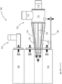
Fig. 1 is a side elevational view of a burner and block assembly of the present disclosure.
Fig. 2 is a top plan view of the flat flame burner subassembly and flat flame burner block of the present disclosure.
FIG. 3 is a side elevational view of a gas nozzle and fuel nozzle of the present disclosure.
FIG. 4A is a front view of a gas nozzle and a fuel nozzle of the present disclosure.
FIG. 4B is a rear view of the gas nozzle and fuel nozzle of the present disclosure.
Fig. 5 is a side elevational view of the burner and block assembly of the present disclosure.
FIG. 6 is a front perspective view of the staged injector subassembly of the present disclosure.
FIG. 7 is a side elevational view of a staging injector subassembly and staging injector block of the present disclosure.
FIG. 8A is an aft side elevational view of a staged injector subassembly and staged injector block of the present disclosure.
FIG. 8B is a top plan view of the staged injector subassembly and staged injector block of the present disclosure.
Fig. 9A is a front side elevational view of the staged injector subassembly of the present disclosure.
Fig. 9B is a side elevational view of the staging injector subassembly of the present disclosure.
FIG. 10 is a front perspective view of a staged injector block of the present disclosure.
Fig. 11A is a front elevational view of a staged injector block of the present disclosure.
Fig. 11B is a rear elevational view of the staged injector block of the present disclosure.
Fig. 12A is a top cross-sectional view of a staged injector block of the present disclosure.
FIG. 12B is a side partial cross-sectional view of the staged injector block of the present disclosure.
Fig. 13A is a side elevational view of a block and burner assembly of the present disclosure.
Fig. 13B is a side elevational view of the block and burner assembly of the present disclosure.
Detailed Description
The present disclosure relates generally to a block and burner assembly arranged to produce a flat flame and allow flexible adaptation between applications requiring staged or non-staged combustion. The block and burner assembly includes a flat flame burner subassembly having a gas nozzle arranged to extend a first distance from a body of the subassembly and a fuel nozzle arranged to protrude a second distance from the body of the subassembly, wherein the first distance is less than or equal to the second distance. This nozzle arrangement helps to prevent flashback and reduces the operating temperature of the subassembly. Further, the block and combustor assembly described herein allows for adaptive placement of the combustor block for different applications and allows for modular replacement and/or repair of separable combustor blocks. Further, in a staged configuration, the block and burner assembly includes a staged injector subassembly secured to the staged injector block, wherein the staged injector block includes a plurality of gas passages operably arranged to more effectively distribute a staged gas flow from the staged injector subassembly to combustion produced by the flat flame burner subassembly.
Exemplary embodiments of the present disclosure are explained below. Although the block and burner assembly shown in the figures is shown in an upward orientation, the illustration of the assembly shown in the figures is not limited to a particular orientation.
Referring now to the drawings, the following description should be viewed with reference to FIGS. 1-2. Fig. 1 illustrates a side elevational view of a burner and block assembly 100 of the present disclosure. The block and combustor assembly 100 includes a flat flame combustor subassembly 102 and a staging injector subassembly 104. The block and combustor assembly 100 further includes a flat flame burner block 106 arranged to receive at least a portion of the flat flame burner subassembly 102 and a staging injector block 108 arranged to receive the staging injector subassembly 104. In one example, the flat flame burner block 106 includes a top surface TS and a bottom surface BS (shown in fig. 13A-13B). It should be appreciated that the flat flame burner block 106 and the staged injector block 108 may be made of a highly insulating material, such as a refractory ceramic material or any other material capable of insulating heat generated during the combustion process described below. As discussed in detail below, the flat flame burner subassembly 102 is arranged to receive gas 120 (shown in fig. 5) and fuel 122 (shown in fig. 5) from respective gas sources (not shown) and respective fuel sources (not shown) and to produce combustion within the flat flame burner block 106. As shown in fig. 1-2, the flat flame burner subassembly 102 may be removably secured to the flat flame burner block 106 by at least one snap C. Moreover, as discussed in further detail below, the staging injector subassembly 104 and the staging injector block 108 may be separate from the flat flame burner subassembly 102 and the flat flame burner block 106.
The flat flame burner subassembly 102 includes a flat flame burner body 110. The flat flame burner body 110 is a single unitary body made of stainless steel (e.g., grade 303, 304, or 310 stainless steel) and may have a plurality of apertures arranged to receive various components discussed below that engage the flat flame burner body 110. In one example, the components discussed below are integral with the flat flame burner body 110 or may be secured to the apertures by a friction fit. Further, the orifices may have pressed or molded female or male helical threads arranged to receive complementary female or male threads of various components engaged with the flat flame burner body 110, as described below. The flat flame burner subassembly 102 also includes a first gas inlet 112, a first fuel inlet 114, a first gas nozzle 116, and a first fuel nozzle 118 (shown in FIG. 2). Further, as shown in fig. 1, 5 and 13A-13B, the flat flame burner body 110 may also be arranged to engage with a flat flame burner subassembly support bracket SB secured to the flat flame burner block 106 to support the weight of the flat flame burner subassembly 102 during operation.
Fig. 2 illustrates a top plan view of the flat flame burner subassembly 102 and the flat flame burner block 108, as shown in fig. 2, the first gas inlet 112 is arranged to engage the flat flame burner body 110 in at least one of the manners described above, and is also arranged to be in fluid communication with a gas source (not shown) such that gas 120 (shown in fig. 5) may be provided from the gas source into the first gas inlet 112 and the flat flame burner body 110. The first gas inlet 112 is a tubular member and may be made of stainless steel, such as grade 303, 304, or 310 stainless steel. It should be appreciated that the first gas inlet 112 may take any size or form sufficient to provide an appropriate volume of gas 120 into the flat flame burner body 110 and subsequently into the first gas nozzle 116, as described below. The gas 120 is oxygen or a gas mixture containing a substantial amount of oxygen. It should be understood that other gas mixtures may be used, such as a gas mixture comprising oxygen or any other gaseous oxidant that supports the combustion process.
The first fuel inlet 114 is arranged to engage with the flat flame burner body 110 in at least one of the manners described above, and is also arranged to be in fluid communication with a fuel source (not shown) such that fuel 122 (shown in fig. 5) can be provided from the fuel source into the first fuel inlet 114 and the flat flame burner body 110. Similar to the first gas inlet 112 as described above, the first fuel inlet 114 is also a tubular member and may be made of stainless steel, such as grade 303, 304, or 310 stainless steel. It should be appreciated that the first fuel inlet 114 may take any size or form sufficient to provide an appropriate volume of fuel 122 into the flat flame burner body 110 and subsequently into the first fuel nozzle 118, as described below. The fuel 122 may be selected from: methane, propane, butane, hydrogen, natural gas, carbon monoxide, any combination of the foregoing, or any other gaseous fuel capable of self-igniting at high temperatures.
As shown in fig. 2, the first gas nozzle 116 includes a first end 124 and a second end 126. It is to be understood that the first end 124 is arranged to engage the flat flame burner body 110 in any of the manners described above. For example, the first end 124 may have an outer peripheral surface machined with threads arranged to engage complementary threads machined on the flat flame burner body 110. These threads can have a variety of thread counts (i.e., threads per inch) and can range from a low thread count, which has the advantage of lower manufacturing costs but at the expense of precision, to a high thread count, which has high precision but also has the disadvantage of higher manufacturing costs. The second end 126 of the first gas nozzle 116 is arranged such that it terminates or ends at a first distance D1 measured from the flat flame burner body 110 along a first direction DR1 relative to the flat flame burner body 110. In addition, the first gas nozzle 116 also includes a through-hole disposed to extend along the length of the first gas nozzle 116 from the first end 124 to the second end 126.
In addition, the flat flame burner subassembly 102 also includes a first fuel nozzle 118. The first fuel nozzle 118 includes a first end 128 and a second end 130. It should be appreciated that the first end 128 is arranged to engage the flat flame burner body 110 in any of the manners described above. Further, as shown, the first end 128 of the first fuel nozzle 118 is arranged to be secured to the first fuel inlet 114, the first fuel inlet 114 being arranged to extend through a cavity created within the flat flame burner body 110. For example, the first end 128 may have an outer peripheral surface machined with threads arranged to engage with complementary threads machined on the flat flame burner body 110 or the first fuel inlet 114. These threads can have a variety of thread counts (i.e., threads per inch) and can range from a low thread count, which has the advantage of lower manufacturing costs but at the expense of precision, to a high thread count, which has high precision but also has the disadvantage of higher manufacturing costs. The second end 130 of the first fuel nozzle 118 is arranged such that it terminates or ends at a second distance D2 measured from the flat flame burner body 110 along a first direction DR1 relative to the flat flame burner body 110, wherein the second distance D2 is greater than the first distance D1. It should also be understood that, although not shown in the figures, the flat flame burner subassembly 102 may be arranged such that the first gas nozzle 116 and the first fuel nozzle 118 terminate at the same distance relative to the flat flame burner body 110, e.g., in the first direction DR1, the first distance D1 is equal to the second distance D2. Additionally, the first fuel nozzle 118 also includes a through-hole arranged to extend along the length of the first fuel nozzle 118 from the first end 128 to the second end 130 such that the first fuel nozzle 118 at least partially circumferentially surrounds the first gas nozzle 116.
The following description should be read with reference to fig. 3-4B. Fig. 3 shows a side view of the flat flame burner subassembly 102. Fig. 4A and 4B show a front side elevation and a back side elevation of the first gas nozzle 116 and the first fuel nozzle 118, respectively. As shown in fig. 3-4B, the first gas nozzle 116 has a first end 124 and a second end 126, wherein the first end 124 is disposed proximate to the flat flame burner body 110 when secured within the flat flame burner subassembly 102. At the first end 124 of the first gas nozzle 116, the nozzle orifice has a first height H1 and a first width W1. In one example, the orifice disposed at the first end 124 of the first gas nozzle 116 is circular and has a first height H1 of between 75-130 millimeters (about 3-5 inches) and has a first width W1 of also between 75-130 millimeters (about 3-5 inches). It should be appreciated that the nozzle orifices at the first end 124 of the first gas nozzle 116 may take any shape and have any size to provide the appropriate volume of gas 120 (shown in FIG. 5) to the combustion process described herein. At the second end 126 of the first gas nozzle 116, the nozzle orifice has a second height H2 and a second width W2, wherein the second height H2 is less than the first height H1 and the second width W2 is greater than the first width W1. In one example, the second height H2 is about 40-65 millimeters (about 1.5-2.5 inches) and the second width W2 is about 15-175 millimeters (about 6-7 inches). As the gas 120 exits the second end 126 of the first gas nozzle 116, the tapered nozzle shape described above acts as a funnel and adjusts the flow shape of the gas 120 (as shown in FIG. 5) such that the gas 120 is provided uniformly across the second width W2 and mixes with the fuel 122 to facilitate combustion, as described below.
Further, the first fuel nozzle 118 has a first end 128 and a second end 130, wherein the first end 128 is disposed proximate to the flat flame burner body 110 when secured within the flat flame burner subassembly 102. At the first end 128 of the first gas nozzle 116, the nozzle orifice has a third height H3 and a third width W3. In one example, the orifices disposed at the first end 128 of the first fuel nozzle 118 are circular and have a third height H3 of between 50-75 millimeters (about 2-3 inches) and a third width W3 of also between 50-75 millimeters (about 2-3 inches). It should be appreciated that the nozzle orifices at the first end 128 of the first fuel nozzle 118 may take any shape and have any size to provide an appropriate volume of fuel 122 (shown in FIG. 5) to the combustion process described herein. At the second end 130 of the first fuel nozzle 118, the nozzle orifice has a fourth height H4 and a fourth width W4, wherein the fourth height H4 is less than the third height H3 and the fourth width W4 is greater than the third width W3. In one example, the fourth height H4 is about 10-40 millimeters (about 0.5-1.5 inches) and the fourth width W4 is about 115 and 165 millimeters (about 4.5-6.5 inches). As the fuel 122 exits the second end 130 of the first fuel nozzle 118, the tapered nozzle shape described above acts as a funnel and adjusts the gas flow shape of the fuel 122 (as shown in FIG. 5) such that the fuel 122 is provided uniformly across the fourth width W4 and mixes with the gas 120 to facilitate combustion, as described below.
As shown in fig. 5, during operation, gas 120 is allowed to flow from a gas source (not shown) to the first gas inlet 112 of the flat flame burner body 110. The gas 120 is forced to flow from the flat flame burner body 110 in a first direction DR1 and within the first gas nozzle 116. The gas 120 flows circumferentially outward from the first fuel nozzle 118 and from a first end 124 to a second end 126 of the first gas nozzle 116. The tapered transition from the first height H1 and first width W1 to the second height H2 and second width W2 of the first gas nozzle 116 defines the shape of the gas 120 as the gas 120 exits the second side 126 of the first gas nozzle 116 for combustion within the flat flame burner block 106. At the same time, fuel 122 is allowed to flow from a fuel source (not shown) to the first fuel inlet 114 of the flat flame burner body 110. Fuel 122 is forced to flow from the first fuel inlet 114 in a first direction DR1 and within the first fuel nozzle 118. The fuel 122 flows within the first fuel nozzle 118 from a first end 128 to a second end 130. The tapered transition from the third height H3 and the third width W3 to the fourth height H4 and the fourth width W4 of the first fuel nozzle 118 defines the shape of the gaseous fuel 122 as the gaseous fuel 122 exits the second end 130 of the first fuel nozzle 118 for combustion within the flat flame burner block 106. The tapered transition of the first gas nozzle 116 and the first fuel nozzle 118 produces combustion of a flame having a flat shape, i.e., a flame that is substantially flat and spans the width of the through-hole in the flat flame burner block 106. The flat flame shape makes the overall burner system more fuel efficient.
The following description should be read with reference to fig. 6-9B. FIG. 6 illustrates a front perspective view of the staging injector subassembly 104. FIG. 7 is a side elevational view of staging injector subassembly 104 secured to staging injector block 108. Fig. 8A and 8B show an aft view and a top plan view, respectively, of the staging injector subassembly 104 secured to the staging injector block 108. Similarly, fig. 9A and 9B show front and side views, respectively, of the staging injector subassembly 104. Staging injector subassembly 104 includes a staging injector body 132. The staging injector body is a single unitary body made of stainless steel (e.g., 303, 304, or 310 grade stainless steel) and may have a plurality of apertures arranged to receive various components discussed below that engage staging injector body 132. In one example, the components discussed below are integral with the staging injector body 132 or may be secured to the orifices by a friction fit. Further, the orifices may have stamped or molded female or male helical threads arranged to receive complementary female or male threads of various components engaged with the staged injector body 132, as described below.
As described above, staging injector body 132 of staging injector subassembly 104 is arranged to be removably secured to staging injector block 108. 10-12B illustrate perspective, front, rear, top, and side views, respectively, of staging injector block 108, as shown in FIGS. 10-12B, staging injector body 108 has a first side 142, a second side 144, a top surface 146, and a bottom surface 148. Near the first side 142, the staged injector block 108 includes a recess 150 and a fastener recess 152. While recess 150 is shown as a rectangular depression, it should be understood that recess 150 may be any size or take any shape that is complementary to the shape of staging injector nozzle 136 such that at least a portion of staging injector nozzle 136 extends into recess 150. Further, as described above, the staging injector body 108 may also include one or more fastener recesses 152, the fastener recesses 152 arranged to receive fasteners, such as bolts or screws, through-holes in the flange 138 of the staging injector subassembly 104.
In one example, as shown in fig. 11A-11B and 12B, each of the plurality of gas passages 154 is arranged at a downward slope or angle such that each gas passage slopes from the first side 142 to the second side 144 in the direction of the flat flame burner block 106. In other words, the orifices (e.g., orifices 156A-156C) of each gas passage disposed near the first side 142 are disposed at a first orifice distance AD1 from the bottom surface 148 of the staged injector block 108 (or at a first orifice distance AD1 from the flat flame burner block 106, as the bottom surface 148 and the flat flame burner block are disposed in contact with each other during operation). In addition, the orifices (e.g., orifices 156D-156F) of each gas passage disposed near the second side 144 are disposed a second orifice distance AD2 from the bottom surface 148 of the staged injector block 108 (or from the flat flame burner block 106), wherein the second orifice distance AD2 is less than the first orifice distance AD 1. The difference in the aperture distance of the first and second sets of apertures results in the gas passages having a downward slope, i.e., sloping from the first side 142 to the second side 144 in the direction of the flat flame burner block 106.
In another example, each of the plurality of gas passages 154 are arranged at a different radial angle relative to each other, i.e., are arranged non-parallel to each other. As shown in FIG. 12A, gas passage 154B is arranged substantially parallel to an imaginary central axis A arranged from first side 142 to second side 144 of staging injector block 108. Further, as shown in fig. 12A, the gas passages 154A are arranged at a first radial angle RA1 and the gas passages 154C are arranged at a second radial angle RA2 with respect to the imaginary central axis a. In one example, the first radial angle RA1 and the second radial angle RA2 are selected from the range of 1-20 degrees, or, more specifically, from the range of 5-8 degrees, or, even more specifically, 6.47 degrees, relative to the central axis a. In one example, the first and second radial angles RA1 and RA2 are selected such that as the gas passages 154A and 154C travel from the first side 142 to the second side 144, the gas passages expand outward at an appropriate radial angle relative to the central axis a such that the gas 120 exiting each gas passage is provided at a location that substantially matches the width of the flat flame produced by the flat flame burner subassembly 102 (e.g., the second width W2 of the flat flame nozzle 116), as described above. The availability of this additional staging gas 120 increases the efficiency of the overall monolith and combustor system 100 after initial combustion by the flat flame combustor subassembly 102. Moreover, the ability to independently regulate the secondary gas flow (i.e., gas flow 120 flowing through staging injector subassembly 104 and into staging injector body 108) allows for enhanced flame control of the flat flame produced by flat flame burner subassembly 102. In one example, the proportion and flow rate of the gas 120 flowing through the staging injector subassembly 104 may be adjusted to increase or decrease the length of the flame produced by the system and/or to increase or decrease the width of the flame produced within the through-holes of the flat flame burner block 106.
As described above, it should be appreciated that the block and combustor system 100 may operate in a staged or ungraded arrangement. In a non-staged arrangement, the block and burner system 100 includes only a flat flame burner subassembly 102 secured to a flat flame burner block 106. In this non-staged arrangement, the ratio of gas 120 to fuel 122 is 2:1 and results in a first efficiency of the overall system. In a staged arrangement, the system includes a flat flame burner subassembly 102 secured to a flat flame burner block 106 and a staged injector subassembly 104 secured to a staged injector block 108. Importantly, in the staged arrangement, the ratio of gas 120 to fuel 122 may be adjusted and/or separated to improve the burner efficiency of the combustion produced by the flat flame burner subassembly 104. In one example, the ratio of gas 120 to fuel 122 combusted in the flat flame burner subassembly is 1:1, while the remainder of the gas 120 is provided by the staging injector subassembly 104. By providing additional staging gas using a plurality of gas passages 154 as described above, the overall efficiency and control of the flame produced by the system can be controlled with greater accuracy.
Further, in the staged arrangement, the staged injector block 108 is arranged to be positioned on top of the flat flame burner block 106 (e.g., in contact with the top surface TS) during operation of the block and burner assembly 100. It should also be appreciated that the staged injector block 108 may be arranged to be secured beneath the flat flame burner block 106 (e.g., in contact with the bottom surface BS) during operation of the block and burner assembly 100. Further, as shown in fig. 13A or 13B, it should be understood that in either configuration (i.e., the staging injector block 108 is disposed above or below the flat flame burner block 106), a bracket 158 or other mechanism may be disposed between the flat flame burner block 106 and the staging injector block 108 to secure the blocks to one another and prevent them from moving relative to one another during operation. Although not shown in the figures, it should be understood that other configurations are possible, for example, the staged injector block 108 is arranged to be secured to the side of the flat flame burner block 106, or the like.
The above-described block and burner system (e.g., block and burner assembly 100) has a number of significant advantages. First, the flat flame burner subassembly 102 produces a flat flame during the combustion process described above, which increases the overall efficiency of the burner. Second, the above-described block and burner assembly allows for precise control of the staging gas flowing through the staging injector subassembly 104 and staging injector block 108, thereby allowing for enhanced control of the flat flame produced in the flat flame burner subassembly 102. Third, the block and burner assembly 100 is flexible in its application. For example, the system may work in conjunction with a flat flame burner subassembly designed for staged combustion (i.e., a burner subassembly that requires additional staged gas to be provided at a different point in the combustion process than initial ignition), or the system may work in conjunction with a flat flame burner subassembly designed for non-staged combustion (i.e., a burner subassembly that does not require additional staged gas). Moreover, because the materials used for the flat flame burner block 106 and the staged injector block 108 are generally brittle and easily break during repeated combustion operations, the block and burner assembly 100 described above allows each portion of the block, i.e., the flat flame burner block 1086 or the staged injector block 108, to be independently replaced and/or repaired. Further, having two blocks separable as described above can prevent cracks initiated in one block from propagating to the other block. Finally, the first gas nozzle 116 and the first fuel nozzle 118 of the flat flame burner subassembly 102 are arranged to extend a first distance D1 from the body of the subassembly and a second distance D2 from the body of the subassembly, respectively, wherein the first distance D1 is less than or equal to the second distance D2. This nozzle arrangement prevents the gas 120 from the first gas nozzle 116 from mixing with the fuel 122 from the first fuel nozzle 118 before exiting the flat flame burner subassembly. The external mixing of the gas 120 and fuel 122 helps to prevent backfire and reduce the operating temperature of the subassembly.
While multiple embodiments are illustrated and described herein, those of ordinary skill in the art will readily envision a variety of other means and/or structures for performing the function and/or obtaining the effect and/or one or more of the advantages described herein, and each of such variations and/or modifications is deemed to be within the scope of the embodiments described herein. More broadly, those skilled in the art will appreciate that all parameters, dimensions, materials, and configurations described herein are exemplary and that the actual parameters, dimensions, materials, and/or configurations are dependent upon the specific application of the teachings herein. Those skilled in the art will recognize, or be able to ascertain using no more than routine experimentation, many equivalents to the specific inventive embodiments described herein. It is, therefore, to be understood that the foregoing embodiments are illustrative only and that, within the scope of the appended claims and equivalents thereto, inventive embodiments other than those specifically described and claimed herein are possible. Inventive embodiments of the present disclosure are directed to each particular feature, system, object, material, and/or method described herein. In addition, any combination of two or more such features, systems, objects, materials and/or methods, if such features, systems, objects, materials and/or methods are not mutually inconsistent, is included within the scope of the present disclosure.
Claims (15)
Applications Claiming Priority (1)
| Application Number | Priority Date | Filing Date | Title |
|---|---|---|---|
| PCT/US2020/017854 WO2021162684A1 (en) | 2020-02-12 | 2020-02-12 | Oxy flat flame burner and block assembly |
Publications (1)
| Publication Number | Publication Date |
|---|---|
| CN115135929A true CN115135929A (en) | 2022-09-30 |
Family
ID=77292483
Family Applications (1)
| Application Number | Title | Priority Date | Filing Date |
|---|---|---|---|
| CN202080096355.9A Pending CN115135929A (en) | 2020-02-12 | 2020-02-12 | Oxygen flat flame burner and block assembly |
Country Status (5)
| Country | Link |
|---|---|
| US (1) | US20230049414A1 (en) |
| EP (2) | EP4103880A4 (en) |
| JP (1) | JP7525622B2 (en) |
| CN (1) | CN115135929A (en) |
| WO (1) | WO2021162684A1 (en) |
Citations (13)
| Publication number | Priority date | Publication date | Assignee | Title |
|---|---|---|---|---|
| EP0335728A2 (en) * | 1988-04-01 | 1989-10-04 | The Boc Group, Inc. | Method and apparatus for gas lancing |
| US5611682A (en) * | 1995-09-05 | 1997-03-18 | Air Products And Chemicals, Inc. | Low-NOx staged combustion device for controlled radiative heating in high temperature furnaces |
| CN1148151A (en) * | 1995-07-17 | 1997-04-23 | 液体空气乔治洛德方法利用和研究有限公司 | Combustion process and apparatus therefor comprising independent injection systems for fuel and oxidant streams |
| CN1186927A (en) * | 1996-11-25 | 1998-07-08 | 液体空气乔治洛德方法利用和研究有限公司 | Combustion process and apparatus therefore containing separate injection of fuel and oxidant streams |
| JPH11132420A (en) * | 1997-09-01 | 1999-05-21 | Tokyo Gas Co Ltd | Oxygen combustion burner and combustion furnace having the burner |
| CN1241697A (en) * | 1998-06-30 | 2000-01-19 | 普拉塞尔技术有限公司 | Wide flame burner |
| US20090280444A1 (en) * | 2008-05-08 | 2009-11-12 | Air Products And Chemicals, Inc. | Highly Radiative Burner and Combustion Process |
| US20100104990A1 (en) * | 2008-10-23 | 2010-04-29 | Sarmiento-Darkin Wladimir Y | Wide flame burner |
| US20100183990A1 (en) * | 2009-01-16 | 2010-07-22 | Air Products And Chemicals, Inc. | Multi-Mode Combustion Device and Method for Using the Device |
| US20110146450A1 (en) * | 2008-08-29 | 2011-06-23 | L'air Liquide Societe Anonyme Pour L'etude Et L'ex Ploitation Des Procedes Georges Claude | Method for Generating Combustion by means of a Burner Assembly and Burner Assembly Therefore |
| CN103322573A (en) * | 2012-03-23 | 2013-09-25 | 中外炉工业株式会社 | Burner apparatus and heating furnace |
| US20180363896A1 (en) * | 2015-12-23 | 2018-12-20 | Flsmidth A/S | A Burner for a Kiln |
| CN210035493U (en) * | 2019-03-19 | 2020-02-07 | 泰安震旦胜日应用材料有限公司 | Novel flat pure oxygen combustor |
Family Cites Families (12)
| Publication number | Priority date | Publication date | Assignee | Title |
|---|---|---|---|---|
| US5575637A (en) * | 1994-11-04 | 1996-11-19 | Air Products And Chemicals, Inc. | Method and device for low-NOx high efficiency heating in high temperature furnaces |
| US5545031A (en) * | 1994-12-30 | 1996-08-13 | Combustion Tec, Inc. | Method and apparatus for injecting fuel and oxidant into a combustion burner |
| US5975886A (en) * | 1996-11-25 | 1999-11-02 | L'air Liquide, Societe Anonyme Pour L'etude Et L'exploitation Des Procedes Georges Claude | Combustion process and apparatus therefore containing separate injection of fuel and oxidant streams |
| FR2757845B1 (en) * | 1996-12-31 | 1999-01-29 | Air Liquide | PROCESS FOR IMPROVING THE THERMAL PROFILE OF GLASS OVENS AND GLASS MELTING OVEN FOR IMPLEMENTING IT |
| US6126438A (en) | 1999-06-23 | 2000-10-03 | American Air Liquide | Preheated fuel and oxidant combustion burner |
| US6939130B2 (en) | 2003-12-05 | 2005-09-06 | Gas Technology Institute | High-heat transfer low-NOx combustion system |
| DE102008063101A1 (en) * | 2008-12-24 | 2010-07-01 | Messer Austria Gmbh | Flat flame burner and method for operating a flat flame burner |
| US10204806B2 (en) * | 2011-09-06 | 2019-02-12 | Arsalan Emami | Modular heater |
| WO2014142988A1 (en) | 2013-03-15 | 2014-09-18 | Honeywell International Inc. | Oxygen-fuel burner with staged oxygen supply |
| US10036551B2 (en) * | 2014-03-24 | 2018-07-31 | Air Products And Chemicals, Inc. | Low-firing rate oxy-fuel flat flame burner with oxygen staging |
| EP3339730B1 (en) * | 2016-12-22 | 2021-08-18 | L'air Liquide, Societe Anonyme Pour L'etude Et L'exploitation Des Procedes Georges Claude | Staged combustion installation and method |
| WO2021136218A1 (en) * | 2019-12-31 | 2021-07-08 | 乔治洛德方法研究和开发液化空气有限公司 | Combustor for fuel combustion and combustion method therefor |
-
2020
- 2020-02-12 US US17/760,254 patent/US20230049414A1/en active Pending
- 2020-02-12 WO PCT/US2020/017854 patent/WO2021162684A1/en not_active Ceased
- 2020-02-12 EP EP20918889.5A patent/EP4103880A4/en active Pending
- 2020-02-12 JP JP2022549065A patent/JP7525622B2/en active Active
- 2020-02-12 CN CN202080096355.9A patent/CN115135929A/en active Pending
- 2020-02-12 EP EP23213512.9A patent/EP4306853A3/en active Pending
Patent Citations (13)
| Publication number | Priority date | Publication date | Assignee | Title |
|---|---|---|---|---|
| EP0335728A2 (en) * | 1988-04-01 | 1989-10-04 | The Boc Group, Inc. | Method and apparatus for gas lancing |
| CN1148151A (en) * | 1995-07-17 | 1997-04-23 | 液体空气乔治洛德方法利用和研究有限公司 | Combustion process and apparatus therefor comprising independent injection systems for fuel and oxidant streams |
| US5611682A (en) * | 1995-09-05 | 1997-03-18 | Air Products And Chemicals, Inc. | Low-NOx staged combustion device for controlled radiative heating in high temperature furnaces |
| CN1186927A (en) * | 1996-11-25 | 1998-07-08 | 液体空气乔治洛德方法利用和研究有限公司 | Combustion process and apparatus therefore containing separate injection of fuel and oxidant streams |
| JPH11132420A (en) * | 1997-09-01 | 1999-05-21 | Tokyo Gas Co Ltd | Oxygen combustion burner and combustion furnace having the burner |
| CN1241697A (en) * | 1998-06-30 | 2000-01-19 | 普拉塞尔技术有限公司 | Wide flame burner |
| US20090280444A1 (en) * | 2008-05-08 | 2009-11-12 | Air Products And Chemicals, Inc. | Highly Radiative Burner and Combustion Process |
| US20110146450A1 (en) * | 2008-08-29 | 2011-06-23 | L'air Liquide Societe Anonyme Pour L'etude Et L'ex Ploitation Des Procedes Georges Claude | Method for Generating Combustion by means of a Burner Assembly and Burner Assembly Therefore |
| US20100104990A1 (en) * | 2008-10-23 | 2010-04-29 | Sarmiento-Darkin Wladimir Y | Wide flame burner |
| US20100183990A1 (en) * | 2009-01-16 | 2010-07-22 | Air Products And Chemicals, Inc. | Multi-Mode Combustion Device and Method for Using the Device |
| CN103322573A (en) * | 2012-03-23 | 2013-09-25 | 中外炉工业株式会社 | Burner apparatus and heating furnace |
| US20180363896A1 (en) * | 2015-12-23 | 2018-12-20 | Flsmidth A/S | A Burner for a Kiln |
| CN210035493U (en) * | 2019-03-19 | 2020-02-07 | 泰安震旦胜日应用材料有限公司 | Novel flat pure oxygen combustor |
Also Published As
| Publication number | Publication date |
|---|---|
| EP4103880A4 (en) | 2024-01-10 |
| EP4103880A1 (en) | 2022-12-21 |
| JP7525622B2 (en) | 2024-07-30 |
| EP4306853A2 (en) | 2024-01-17 |
| WO2021162684A1 (en) | 2021-08-19 |
| JP2023523122A (en) | 2023-06-02 |
| US20230049414A1 (en) | 2023-02-16 |
| EP4306853A3 (en) | 2024-04-24 |
Similar Documents
| Publication | Publication Date | Title |
|---|---|---|
| CN107448943B (en) | Perforated flame holder and burner comprising a perforated flame holder | |
| AU2005203537B2 (en) | Burner and method for combusting fuels | |
| US20100089066A1 (en) | Cool flame combustion | |
| US20100095675A1 (en) | Combustor Burner Vanelets | |
| JP2011226773A (en) | Apparatus and method for fuel nozzle | |
| CN114761730B (en) | Burners and combustion methods for fuel combustion | |
| CN101818901A (en) | Premixed direct injection disk | |
| US6132204A (en) | Wide flame burner | |
| CN104136851A (en) | A combustor nozzle and method of supplying fuel to a combustor | |
| US20100159409A1 (en) | Non-centric oxy-fuel burner for glass melting systems | |
| CN115135929A (en) | Oxygen flat flame burner and block assembly | |
| Tacina et al. | Experimental sector and flame-tube evaluations of a multipoint integrated module concept for low emission combustors | |
| CN101379346B (en) | Gas burner with optimized nozzle arrangement | |
| EP1995521A1 (en) | Swirler vane | |
| CN113508261B (en) | Oxygen forehearth burner components | |
| CN101688669A (en) | Fuel distributor | |
| JP5686646B2 (en) | Burner | |
| RU2768639C2 (en) | Radiation wall burner | |
| AU2008200617B2 (en) | Burner and method for combusting fuels | |
| TWI890040B (en) | Provides a method and device for enhancing graded oxygen controlled oxygen combustion | |
| US20250060095A1 (en) | Burner and Method of Operation | |
| TW200505806A (en) | Manufacturing method of optical fiber base material | |
| CN110325794B (en) | Heating device and heating method | |
| JPS6016835Y2 (en) | Mixed gas hand burner for crafting | |
| HK1130875B (en) | Gas burner with optimized nozzle arrangement |
Legal Events
| Date | Code | Title | Description |
|---|---|---|---|
| PB01 | Publication | ||
| PB01 | Publication | ||
| SE01 | Entry into force of request for substantive examination | ||
| SE01 | Entry into force of request for substantive examination |