CN115083724B - Magnetic field coil with magnetic field distribution adjusting function - Google Patents
Magnetic field coil with magnetic field distribution adjusting function Download PDFInfo
- Publication number
- CN115083724B CN115083724B CN202210978785.4A CN202210978785A CN115083724B CN 115083724 B CN115083724 B CN 115083724B CN 202210978785 A CN202210978785 A CN 202210978785A CN 115083724 B CN115083724 B CN 115083724B
- Authority
- CN
- China
- Prior art keywords
- coil
- magnetic field
- support arm
- adjusting function
- rotating
- Prior art date
- Legal status (The legal status is an assumption and is not a legal conclusion. Google has not performed a legal analysis and makes no representation as to the accuracy of the status listed.)
- Active
Links
- RYGMFSIKBFXOCR-UHFFFAOYSA-N Copper Chemical compound [Cu] RYGMFSIKBFXOCR-UHFFFAOYSA-N 0.000 claims description 3
- 229910052802 copper Inorganic materials 0.000 claims description 3
- 239000010949 copper Substances 0.000 claims description 3
- 230000002093 peripheral effect Effects 0.000 claims description 3
- 230000007704 transition Effects 0.000 claims description 3
- 230000006978 adaptation Effects 0.000 claims description 2
- 230000008859 change Effects 0.000 abstract description 7
- 238000010586 diagram Methods 0.000 description 6
- 238000000034 method Methods 0.000 description 1
- 238000012986 modification Methods 0.000 description 1
- 230000004048 modification Effects 0.000 description 1
- 230000035515 penetration Effects 0.000 description 1
- 230000008569 process Effects 0.000 description 1
- 238000007789 sealing Methods 0.000 description 1
Images


Classifications
-
- H—ELECTRICITY
- H01—ELECTRIC ELEMENTS
- H01F—MAGNETS; INDUCTANCES; TRANSFORMERS; SELECTION OF MATERIALS FOR THEIR MAGNETIC PROPERTIES
- H01F7/00—Magnets
- H01F7/06—Electromagnets; Actuators including electromagnets
- H01F7/20—Electromagnets; Actuators including electromagnets without armatures
- H01F7/202—Electromagnets for high magnetic field strength
-
- A—HUMAN NECESSITIES
- A61—MEDICAL OR VETERINARY SCIENCE; HYGIENE
- A61N—ELECTROTHERAPY; MAGNETOTHERAPY; RADIATION THERAPY; ULTRASOUND THERAPY
- A61N2/00—Magnetotherapy
- A61N2/02—Magnetotherapy using magnetic fields produced by coils, including single turn loops or electromagnets
Landscapes
- Electromagnetism (AREA)
- Physics & Mathematics (AREA)
- Engineering & Computer Science (AREA)
- Health & Medical Sciences (AREA)
- Power Engineering (AREA)
- Animal Behavior & Ethology (AREA)
- Life Sciences & Earth Sciences (AREA)
- General Health & Medical Sciences (AREA)
- Public Health (AREA)
- Veterinary Medicine (AREA)
- Radiology & Medical Imaging (AREA)
- Nuclear Medicine, Radiotherapy & Molecular Imaging (AREA)
- Biomedical Technology (AREA)
- Magnetic Resonance Imaging Apparatus (AREA)
Abstract
The invention discloses a magnetic field coil with magnetic field distribution adjusting function, which comprises: the rotating frames are symmetrically arranged and hinged on two sides of a magnetic field focusing area of the shell; a first coil and a second coil provided on the support frame of the rotating frame; the first coil and the second coil are the same in shape, and at least one circular arc-shaped support arm is arranged in the first coil and the second coil; the first coil and the second coil are mutually abutted in a magnetic field focusing area, and the position of rotating the first coil and the second coil changes the support arm positioned on the magnetic field focusing part, so that the magnetic field distribution range at the magnetic field focusing part can be changed. The design scheme that the straight line support arm and the arc support arm are tangent and adjacent can ensure that the change of a magnetic field generated by the coil is finished on the premise of not changing the shape of the coil, and meanwhile, the design can ensure that the use of the coil and a cable cannot be influenced when the angle and the position are changed.
Description
Technical Field
The invention belongs to the technical field of electromagnetic coils, and particularly relates to a magnetic field coil with a magnetic field distribution adjusting function.
Background
The 8-shaped coil has a certain magnetic field focusing property, so that the 8-shaped coil is widely applied in the medical industry, and particularly on transcranial magnetic products, the 8-shaped coil becomes a standard component thereof. However, most of the existing 8-shaped coils are combined by two circular coils, the coils are in a non-adjustable state, and the magnetic field can be adjusted only by adjusting the current parameters flowing through the coils.
Since the magnetic field distribution state of the 8-shaped coil has a certain relation with the form of the coil, especially the magnetic field distribution range, the fixed magnetic field coil represents that the distribution range of the generated magnetic field is also fixed, and the adjustment cannot be carried out.
Disclosure of Invention
In order to solve the above problems, the present invention provides a magnetic field coil having a magnetic field distribution adjusting function, which realizes the adjustment of the magnetic field distribution by using a specially designed coil structure.
A magnetic field coil with a magnetic field distribution adjusting function comprises rotating frames which are symmetrically arranged and are hinged to two sides of a magnetic field focusing area of a shell; a first coil and a second coil provided on the support frame of the rotating frame; the first coil and the second coil are in the same shape, and both the first coil and the second coil at least comprise an arc-shaped support arm; the first coil and the second coil are mutually abutted in a magnetic field focusing area, and the first coil and the second coil are rotated to change the support arm of the coil positioned on the magnetic field focusing part and change the magnetic field distribution range of the magnetic field focusing part.
Furthermore, the first coil and the second coil both comprise two first straight line support arms and second straight line support arms which are tangent to the circular arc support arms and have different lengths.
Furthermore, the first coil and the second coil have the same number of turns, and the cross section of the first coil and the second coil is rectangular or triangular; the adjacent side surfaces of the first coil and the second coil are vertical surfaces.
Furthermore, the first coil and the second coil are fixedly arranged on the peripheral surface of the supporting frame, a rotating shaft is arranged in the supporting frame, and the supporting frame is fixedly arranged in the shell through the rotating shaft; the rotating shaft and the circular arc-shaped supporting arm are coaxially arranged.
Furthermore, the rotating shaft is also provided with gears, two ends of the rotating shaft of the rotating frame are hinged and installed in hinge holes in the shell, and the gears on the two rotating shafts are meshed with each other; the one end that the gear was kept away from to the pivot stretch out the shell setting, the one end tip that stretches out the shell is equipped with the adjusting device who is used for the adaptation spanner.
Furthermore, the hinge holes are arranged on the left side and the right side of a magnetic field focusing area on the shell; the distance between the two hinge holes is equal to the diameter length of the circular arc-shaped support arm; the hinge holes on the left side and the right side of the magnetic field focusing area are symmetrically arranged.
Furthermore, a connecting terminal for an external cable, a first coil and a second coil is also arranged on the rotating shaft of the rotating frame; the cable is connected with the first coil and the second coil through the connecting terminal.
Furthermore, the first coil and the second coil are coils wound by copper wires, and the number of turns of the first coil is the same as that of the second coil; the current directions of the first coil and the second coil at the magnetic field focusing area are the same.
Furthermore, the length of the first straight supporting arm is equal to the radius length of the circular arc-shaped supporting arm; the length of the second straight line support arm is equal to the diameter length of the circular arc support arm. The included angle between the first straight line support arm and the second straight line support arm is 0-175 degrees.
Furthermore, the first coil and the second coil also comprise a third support arm; the third support arm is connected with the first linear support arm and the second linear support arm, and circular arc transition is arranged at the connection position.
The invention provides a magnetic field coil with magnetic field distribution adjusting function, comprising: the rotating frames are symmetrically arranged and hinged on two sides of a magnetic field focusing area of the shell; a first coil and a second coil provided on the support frame of the rotating frame; the first coil and the second coil are the same in shape and both comprise at least one circular arc-shaped support arm; the first coil and the second coil are mutually abutted in a magnetic field focusing area, and the first coil and the second coil are rotated to change the support arm of the coil positioned on the magnetic field focusing part and change the magnetic field distribution range of the magnetic field focusing part. The design scheme that the straight line support arm and the circular arc support arm are tangent and adjacent is adopted, the change of a magnetic field generated by the coil can be guaranteed to be completed on the premise that the shape of the coil is not changed, and meanwhile, the design can guarantee that the use of the coil and a cable cannot be influenced when the angle and the position are changed.
Drawings
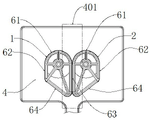
Fig. 1 is a front view of a magnetic field coil having a magnetic field distribution adjusting function according to the present invention;
fig. 2 isbase:Sub>A sectional viewbase:Sub>A-base:Sub>A ofbase:Sub>A magnetic field coil havingbase:Sub>A magnetic field distribution adjusting function according to the present invention;
fig. 3 is a front view of a first coil of a field coil having a magnetic field distribution adjusting function according to the present invention;
fig. 4 is a B-B sectional view of a first coil of a field coil having a magnetic field distribution adjusting function according to the present invention;
fig. 5 is a perspective view of a first coil of a magnetic field coil having a magnetic field distribution adjusting function according to the present invention;
fig. 6 is a perspective view of a first coil and a rotating frame of a magnetic field coil with a magnetic field distribution adjusting function according to the present invention;
fig. 7 is a schematic diagram of the two coils of the magnetic field coil with the magnetic field distribution adjusting function of the present invention with arc-shaped arms abutting against each other;
FIG. 8 is a schematic diagram of the second linear arms of two coils of a magnetic field coil with magnetic field distribution adjusting function abutting against each other according to the present invention;
FIG. 9 is a schematic diagram of two coils of a magnetic field coil with magnetic field distribution adjusting function with their first linear arms abutting against each other according to the present invention;
fig. 10 is a perspective view of the two coils of the magnetic field coil with magnetic field distribution adjusting function of the present invention with arc-shaped arms abutting against each other;
fig. 11 is a schematic diagram showing relative coordinates of a first coil and a second coil of a magnetic field coil with a magnetic field distribution adjusting function according to the present invention;
fig. 12 is a diagram showing a magnetic field intensity distribution in the X-axis direction of a magnetic field coil having a magnetic field distribution adjusting function according to the present invention;
fig. 13 is a Y-axis magnetic field intensity distribution diagram of a magnetic field coil having a magnetic field distribution adjusting function according to the present invention.
Detailed Description
Example (b):
referring to fig. 1-13, a magnetic field coil with magnetic field distribution adjusting function includes a first coil 1, a second coil 2, a rotating frame 3, and a housing 4;
the first coil 1 and the second coil 2 are coils wound by copper wires, and the number of turns of the first coil 1 is the same as that of the second coil 2;
the first coil 1 and the second coil 2 have the same shape, and the first coil 1 and the second coil 2 respectively comprise an arc-shaped support arm 61, a first straight support arm 62, a second straight support arm 63 and a third support arm 64;
the circular arc-shaped support arm 61 is in a semicircular arc shape, the first linear support arm 62 and the second linear support arm 63 are respectively connected with two ends of the circular arc-shaped support arm 61, and the first linear support arm 62 and the second linear support arm 63 are respectively tangent to the circular arc-shaped support arm 61;
the third support arm 64 is connected with the first linear support arm 62 and the second linear support arm 63, and the connecting positions are provided with circular arc transition;
the length of the first linear support arm 62 is different from that of the second linear support arm 63;
the length of the first straight supporting arm 62 is equal to the radius length of the circular arc supporting arm 61;
the length of the second straight support arm 63 is equal to the diameter of the circular arc support arm 61;
the included angle between the first linear support arm 62 and the second linear support arm 63 is 0-175 degrees;
the first coil 1 and the second coil 2 have the same number of turns, and the cross section is rectangular or triangular;
the cross sections of the first coil 1 and the second coil 2 are preferably triangular and isosceles triangular;
the adjacent side surfaces of the first coil 1 and the second coil 2 are vertical surfaces, namely the peripheral side surfaces of the first coil 1 and the second coil 2 are vertical surfaces, so that the maximum contact area of two surfaces of the two coils which are in contact with each other is ensured;
a rotating frame 3 for fixing is arranged inside the first coil 1 and the second coil 2;
the rotating frame 3 comprises a rotating shaft 31 and a supporting frame 32 which are fixedly arranged with each other;
the supporting frame 32 is matched with the inner shapes of the first coil 1 and the second coil 2, and the first coil 1 and the second coil 2 are wound on the outer surface of the supporting frame 32;
the rotating shaft 31 is fixedly arranged inside the supporting frame 32;
the rotating shaft 31 is coaxial with the circular arc-shaped support arm 61;
the rotating shaft 31 is also provided with a gear 33, and the gear 33 is arranged at one end of the rotating shaft;
the first coil 1, the second coil 2 and the rotating frame 3 are arranged inside the shell 4;
the shell 4 is in a rectangular box shape;
a magnetic field focusing area 401 is arranged in the middle of the shell 4;
the hinge holes 41 on the left side and the right side of the magnetic field focusing region 401 are symmetrically arranged;
the first coil 1, the second coil 2 and the rotating frame 3 are arranged inside the shell 4;
two ends of the rotating shaft 31 of the rotating frame 3 are hinged on the hinge holes 41, the gears 33 on the two rotating shafts 31 are meshed with each other, and the first coil 1 and the second coil 2 are symmetrically arranged around the central axis of the shell 4;
one end of the rotating shaft 31, which is far away from the gear 33, extends out of the shell 4;
a sealing device is arranged between the rotating shaft 31 and the hinge hole 41;
an adjusting device 311 for adapting to a wrench is arranged at one end part of the rotating shaft 31 extending out of the shell 4;
the adjusting device 311 can be a socket wrench hole or other shapes;
the first coil 1 and the second coil 2 are mutually abutted, and two circular arc-shaped support arms 61 or two first straight support arms 62 or two second straight support arms 63 of the first coil 1 and the second coil 2 can be adjusted to be mutually abutted by rotating the rotating shaft 31;
the current directions of the first coil 1 and the second coil 2 at the magnetic field focusing region 401 are the same;
when the maximum adjusting range of the rotating shaft 31 is-90 to 90 degrees and the rotating shaft is located at 0 degree, the two arc-shaped support arms 61 of the first coil 1 and the second coil 2 are abutted against each other; when the rotating shaft is positioned at an angle between 0 and 90 degrees, the two first linear support arms 62 of the first coil 1 and the second coil 2 are arranged in an abutting mode; when the rotating shaft is positioned at an angle between minus 90 degrees and 0 degrees, the two second linear support arms 63 of the first coil 1 and the second coil 2 are arranged in an abutting mode;
the rotating shaft 31 of the rotating frame 3 is also provided with a terminal 312 for connecting an external cable with the first coil 1 and the second coil 2;
the cable is connected to the first coil 1 and the second coil 2 via a connection terminal 312.
When the device is used, a cable is connected with the first coil 1 and the second coil 2 through the connecting terminal 312 to provide power for the coils, the first coil 1 and the second coil 2 form an 8-shaped coil, and the relative positions of the first coil 1 and the second coil 2 can be adjusted by rotating the rotating shaft 31 through a wrench; when the rotating shaft is located at 0 degree, the two circular arc-shaped support arms 61 of the first coil 1 and the second coil 2 are abutted against each other to form a magnetic field formed by mutually combining the two circular coils, the maximum magnetic field intensity is formed at the tangent point of the first coil 1 and the second coil 2, the magnetic field is in a conical peak shape, the magnetic field has better magnetic field penetrability and larger distribution range, and the distribution condition of the magnetic field is shown as the adjacent magnetic field distribution curves of the circular arc-shaped support arms in fig. 12 and 13; when the rotating shaft is located at an angle between 0 and 90 degrees, the two first linear support arms 62 of the first coil 1 and the second coil 2 are abutted against each other, the maximum magnetic field intensity is formed at the two linear support arms at the moment, the position of the maximum magnetic field intensity is linear, the magnetic field is in a conical sheet shape, the magnetic field penetrability is better, the longitudinal distribution range is larger, and the distribution condition of the magnetic field is shown as the adjacent magnetic field distribution curve of the first linear support arms in fig. 12 and 13; when the rotating shaft is positioned at an angle between-90 and 0 degrees, the two second linear support arms 63 of the first coil 1 and the second coil 2 are arranged in an abutting mode; at this time, the maximum magnetic field intensity is formed at the two linear arms, the position of the maximum magnetic field intensity is linear, the magnetic field is in a tapered sheet shape, the magnetic field penetration is good, the length of the second linear arm 63 is longer than that of the first linear arm 62, the distribution range in the X-axis direction is wide at this time, the magnetic field is larger than that formed by the two first linear arms 62, and the distribution of the magnetic field is as shown by the adjacent magnetic field distribution curves of the second linear arms in fig. 12 and 13.
When in use, the rotating shaft 31 is rotated, so that the relative positions of the first coil 1 and the second coil 2 can be adjusted; at this moment, because the gears 33 on the rotating shafts are meshed with each other, the rotating angles of the first coil 1 and the second coil 2 positioned on two sides of the magnetic field focusing area 401 can keep the same relative angle, the rotating shafts are always concentrically arranged with the circular arc-shaped coils in the rotating process, and the two coils are always kept in a mutually tight abutting state, because the first linear support arm 62 and the second linear support arm 63 are respectively arranged in a tangent mode with the circular arc-shaped support arm 61, the mutual abutting positions of the two coils can be changed by rotating the coils to a certain angle, when the mutual abutting positions of the two coils are switched from the circular arc-shaped support arms to the linear support arms to abut against each other, the distribution of the combined magnetic field generated by the coils is changed, the magnetic field focusing position is changed into a line from a point, and the distribution range of the magnetic field is increased. Because the coils which play a main role in the coils are the first linear support arm 62, the second linear support arm 63 and the circular arc support arm 61, the first linear support arm 62 and the second linear support arm 63 are respectively arranged at two sides of the circular arc support arm 61, and the two coils are respectively rotated within the range of 90-180 to complete the switching of the coil forms, the situation that the cable connected with the coils is wound and folded due to the fact that the cable is rotated or moved by too large distance can be guaranteed, and the use is not affected.
The design scheme that the straight line support arm and the arc support arm are tangent and adjacent can ensure that the change of a magnetic field generated by the coil is finished on the premise of not changing the shape of the coil, and meanwhile, the design can ensure that the use of the coil and a cable cannot be influenced when the angle and the position are changed.
The above-mentioned embodiments, objects, technical solutions and advantages of the present invention are further described in detail, it should be understood that the above-mentioned embodiments are only illustrative of the present invention and are not intended to limit the present invention, and any modifications, equivalents, improvements and the like made within the spirit and principle of the present invention should be included in the protection scope of the present invention.
Claims (7)
1. A magnetic field coil with a magnetic field distribution adjusting function is characterized in that: comprises rotating frames which are symmetrically arranged and are hinged with two sides of a magnetic field focusing area of a shell;
a first coil and a second coil provided on the support frame of the rotating frame; the first coil and the second coil are the same in shape and both comprise at least one circular arc-shaped support arm;
the first coil and the second coil are mutually abutted in a magnetic field focusing region, and the supporting arm of the coil at the magnetic field focusing part can be changed by rotating the first coil and the second coil, so that the magnetic field distribution range at the magnetic field focusing part is changed; the first coil and the second coil respectively comprise a first linear supporting arm and a second linear supporting arm which are tangent to the circular arc supporting arm and have different lengths; the first coil and the second coil have the same number of turns, and the cross section of the first coil and the second coil is rectangular or triangular; the adjacent side surfaces of the first coil and the second coil are vertical surfaces; the first coil and the second coil are fixedly arranged on the peripheral surface of the supporting frame, a rotating shaft is arranged in the supporting frame, and the supporting frame is fixedly arranged in the shell through the rotating shaft; the rotating shaft and the arc-shaped support arm are coaxially arranged.
2. A magnetic field coil having a magnetic field distribution adjusting function as defined in claim 1, wherein: the rotating shaft is also provided with a gear, two ends of the rotating shaft of the rotating frame are hinged and installed in the hinge holes on the shell, and the gears on the two rotating shafts are meshed with each other; the one end that the gear was kept away from to the pivot stretch out the shell setting, the one end tip that stretches out the shell is equipped with the adjusting device who is used for the adaptation spanner.
3. A magnetic field coil having a magnetic field distribution adjusting function as claimed in claim 2, wherein: the hinge holes are arranged on the left side and the right side of a magnetic field focusing area on the shell; the distance between the two hinge holes is equal to the diameter length of the circular arc-shaped support arm; the hinge holes on the left side and the right side of the magnetic field focusing area are symmetrically arranged.
4. A magnetic field coil having a magnetic field distribution adjusting function as defined in claim 3, wherein: the rotating shaft of the rotating frame is also provided with a connecting terminal for an external cable, a first coil and a second coil; the cable is connected with the first coil and the second coil through the connecting terminal.
5. A magnetic field coil having a magnetic field distribution adjusting function as defined in claim 4, wherein: the first coil and the second coil are coils wound by copper wires, and the number of turns of the first coil and the number of turns of the second coil are the same; the current directions of the first coil and the second coil at the magnetic field focusing area are the same.
6. A magnetic field coil having a magnetic field distribution adjusting function as set forth in claim 5, wherein: the length of the first straight supporting arm is equal to the radius length of the circular arc-shaped supporting arm; the length of the second linear support arm is equal to the diameter length of the circular arc support arm; the included angle between the first straight line support arm and the second straight line support arm is 0-175 degrees.
7. A magnetic field coil having a magnetic field distribution adjusting function as defined in claim 6, wherein: the first coil and the second coil also comprise a third support arm; the third support arm is connected with the first linear support arm and the second linear support arm, and circular arc transition is arranged at the connection position.
Priority Applications (1)
| Application Number | Priority Date | Filing Date | Title |
|---|---|---|---|
| CN202210978785.4A CN115083724B (en) | 2022-08-16 | 2022-08-16 | Magnetic field coil with magnetic field distribution adjusting function |
Applications Claiming Priority (1)
| Application Number | Priority Date | Filing Date | Title |
|---|---|---|---|
| CN202210978785.4A CN115083724B (en) | 2022-08-16 | 2022-08-16 | Magnetic field coil with magnetic field distribution adjusting function |
Publications (2)
| Publication Number | Publication Date |
|---|---|
| CN115083724A CN115083724A (en) | 2022-09-20 |
| CN115083724B true CN115083724B (en) | 2022-11-11 |
Family
ID=83244003
Family Applications (1)
| Application Number | Title | Priority Date | Filing Date |
|---|---|---|---|
| CN202210978785.4A Active CN115083724B (en) | 2022-08-16 | 2022-08-16 | Magnetic field coil with magnetic field distribution adjusting function |
Country Status (1)
| Country | Link |
|---|---|
| CN (1) | CN115083724B (en) |
Families Citing this family (8)
| Publication number | Priority date | Publication date | Assignee | Title |
|---|---|---|---|---|
| US20180001107A1 (en) | 2016-07-01 | 2018-01-04 | Btl Holdings Limited | Aesthetic method of biological structure treatment by magnetic field |
| US10695575B1 (en) | 2016-05-10 | 2020-06-30 | Btl Medical Technologies S.R.O. | Aesthetic method of biological structure treatment by magnetic field |
| US11464993B2 (en) | 2016-05-03 | 2022-10-11 | Btl Healthcare Technologies A.S. | Device including RF source of energy and vacuum system |
| US12558146B2 (en) | 2019-04-11 | 2026-02-24 | Btl Medical Solutions A.S. | Methods and devices for aesthetic treatment of biological structures by radiofrequency and magnetic energy |
| US12611545B2 (en) | 2020-05-04 | 2026-04-28 | Btl Healthcare Technologies A.S. | Device and method for unattended treatment of a patient |
| JP2023515722A (en) | 2020-05-04 | 2023-04-13 | ビーティーエル ヘルスケア テクノロジーズ エー.エス. | Devices and methods for unattended care of patients |
| US11878167B2 (en) | 2020-05-04 | 2024-01-23 | Btl Healthcare Technologies A.S. | Device and method for unattended treatment of a patient |
| US20260097226A1 (en) | 2024-10-08 | 2026-04-09 | Btl Medical Solutions A.S. | Devices and methods for application of a magnetic field to the nervous system |
Citations (3)
| Publication number | Priority date | Publication date | Assignee | Title |
|---|---|---|---|---|
| CN203736713U (en) * | 2014-03-13 | 2014-07-30 | 中国人民解放军兰州军区乌鲁木齐总医院 | Adjustable focus type focusing electromagnetic field transmitting coil |
| CN210575334U (en) * | 2019-08-30 | 2020-05-19 | 中国船舶工业系统工程研究院 | Double-winding magnetic field coil with variable parameters and structure |
| CN212967286U (en) * | 2020-08-20 | 2021-04-13 | 青岛理工大学 | Electromagnetic field device capable of adjusting any angle |
-
2022
- 2022-08-16 CN CN202210978785.4A patent/CN115083724B/en active Active
Patent Citations (3)
| Publication number | Priority date | Publication date | Assignee | Title |
|---|---|---|---|---|
| CN203736713U (en) * | 2014-03-13 | 2014-07-30 | 中国人民解放军兰州军区乌鲁木齐总医院 | Adjustable focus type focusing electromagnetic field transmitting coil |
| CN210575334U (en) * | 2019-08-30 | 2020-05-19 | 中国船舶工业系统工程研究院 | Double-winding magnetic field coil with variable parameters and structure |
| CN212967286U (en) * | 2020-08-20 | 2021-04-13 | 青岛理工大学 | Electromagnetic field device capable of adjusting any angle |
Also Published As
| Publication number | Publication date |
|---|---|
| CN115083724A (en) | 2022-09-20 |
Similar Documents
| Publication | Publication Date | Title |
|---|---|---|
| CN115083724B (en) | Magnetic field coil with magnetic field distribution adjusting function | |
| CN109212504B (en) | Low scattering carrier with both forward and sideways designs | |
| US7750763B2 (en) | Waveguide bend having a square shape cross-section | |
| EP1084871A3 (en) | Trailer coupling with axial deplacement | |
| DE69606602T2 (en) | SOCKETED ELECTRIC LAMP | |
| CA2608917A1 (en) | Waveguide transitions and method of forming components | |
| CN105572484B (en) | A kind of TEM cell impedance matching methods and device | |
| CN203248519U (en) | Rotation-prevention spherical joint | |
| JP2002151218A (en) | Coaxial elbow | |
| CN211957851U (en) | Circular arc phase shifter | |
| CN218134615U (en) | Mechanism for adjusting bending angle of flat wire on motor manufacturing equipment | |
| CN112909490A (en) | Be applied to on-vehicle glass antenna and vehicle glass | |
| CN216638741U (en) | Angle-adjustable auxiliary arm for lorry-mounted crane | |
| JP2008166856A (en) | Antenna structure | |
| CN209217126U (en) | Cross roller arrangement and up- coiler | |
| CN223903201U (en) | Internal supporting device for welding cylindrical structure | |
| CN2795519Y (en) | Rack rod joint connector | |
| CN210897691U (en) | Grounding wire clamp applied to 90-degree corner | |
| EP0894336A1 (en) | Incandescent lamp with reflection coating | |
| CN215771566U (en) | Broadband antenna with multidirectional adjusting mechanism | |
| CN223093168U (en) | Electrical coupling unit for high-voltage power transmission and distribution | |
| CN115283482A (en) | Electricity core utmost point ear preforming equipment | |
| CN220171865U (en) | Coil, inductance device and electronic equipment | |
| CN217853244U (en) | Novel connector for external fixing support | |
| CN222430519U (en) | Fixing device is used in processing of fiber woven pultrusion cable protection sleeve |
Legal Events
| Date | Code | Title | Description |
|---|---|---|---|
| PB01 | Publication | ||
| PB01 | Publication | ||
| SE01 | Entry into force of request for substantive examination | ||
| SE01 | Entry into force of request for substantive examination | ||
| GR01 | Patent grant | ||
| GR01 | Patent grant |