The invention was made with government support under contract # N00014-16-C-3042 awarded by the naval research office. The government has certain rights in this invention. This patent application publication describes inventive aspects including various novel innovations (hereinafter "publications"), and contains material that is protected by copyright, mask work, and/or other intellectual property. The corresponding owner of the intellectual property right has no objection to the facsimile reproduction by anyone of the disclosure in the published patent office files/records but otherwise reserves all rights whatsoever.
Drawings
The appendix and/or drawings represent various non-limiting example innovative aspects in accordance with the present description:
FIG. 1 illustrates the shape of a corrugated strip fin in one embodiment;
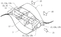
FIG. 2 illustrates the configuration of corrugated strip fins assembled into a mechanism in one embodiment;
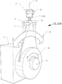
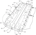
FIG. 3 shows details of the transmission assembly in one embodiment;
FIG. 4 shows details of the transmission assembly in one embodiment;
FIG. 5 shows details of the transmission assembly in one embodiment;
FIG. 6 illustrates an embodiment attached to a vessel and the mode of operation in one embodiment;
FIG. 7 illustrates an embodiment of a free-swimming vessel in one embodiment;
FIG. 8 illustrates an embodiment of a vessel or vehicle capable of moving on land in one embodiment;
FIG. 9 illustrates an embodiment attached to a non-moving object or substrate and the mode of operation in one embodiment;
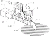
FIG. 10 shows another implementation of an embodiment;
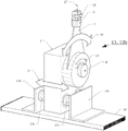
FIG. 11 shows details of the transmission assembly in one embodiment;
FIG. 12 shows an embodiment attached to a vessel in one embodiment;
FIG. 13 shows an embodiment attached to a non-movable object or substrate in one embodiment;
FIG. 14 shows another implementation of an embodiment;
FIG. 15 shows details of a drive assembly of an embodiment;
FIG. 16 illustrates an embodiment having two fins sharing a common actuator in one embodiment;
FIG. 17 illustrates an embodiment having two fins on two sets of actuators in one embodiment;
FIG. 18 illustrates an embodiment having two pairs of fins on two sets of actuators in one embodiment;
FIG. 19 is a schematic view of an embodiment having two fins sharing a common actuator in one embodiment;
FIG. 20 is a schematic view of an embodiment having two fins on two sets of actuators in one embodiment;
FIG. 21 is a schematic view of an embodiment having two pairs of fins on two sets of actuators in one embodiment;
FIG. 22 shows an embodiment with a cam in one embodiment;
FIG. 23 shows details of the drive assembly of the embodiment with a cam in one embodiment;
FIG. 24 shows details of another embodiment of a drive assembly having a cam in one embodiment;
FIG. 25 illustrates an embodiment with two pairs of fins sharing a cam driven actuator in one embodiment;
FIG. 26 shows an embodiment with two pairs of fins sharing a cam driven actuator in another embodiment;
FIG. 27 illustrates a generator implementation in one embodiment;
28-29 illustrate arcuate vanes added to one edge of an arcuate flexible sheet of material in one embodiment;
FIG. 30 depicts a cross-sectional view through an edge of a flexible sheet material in one embodiment;
FIG. 31 shows a cross-sectional view of an embodiment where the arcuate blade has a thickening or flange along the edge in one embodiment;
FIG. 32 illustrates an embodiment of an arcuate blade wherein, in one embodiment, the outer radius edge of the arcuate blade forms a continuous arc but its inner edge includes a series of narrow tabs;
FIG. 33 illustrates an embodiment of two or more composite fins, each coupled to two or more drive assemblies, in one embodiment;
FIG. 34 illustrates an embodiment of a shaft having conjugate cams for each composite fin in one embodiment;
35-36 illustrate an implementation of a thrust module in some embodiments;
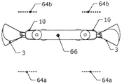
figure 37 illustrates an embodiment of a thrust module coupled by at least one flexible coupling member in one embodiment;
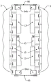
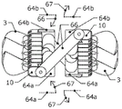
38-39 illustrate views of an embodiment of a coupled thrust module in a default operating position in one embodiment;
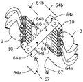
40-41 illustrate views of an embodiment of a coupled thrust module in another operational position in one embodiment;
42-43 show views of an embodiment of a coupled thrust module in another operating position in one embodiment;
44-45 show views of an embodiment of a coupled thrust module in another operating position in one embodiment;
FIG. 46 illustrates an embodiment of a thrust module coupled to a second chassis in one embodiment;
FIG. 47 illustrates an embodiment of a coupled thrust module having a fairing and a vehicle payload in one embodiment; and
48-52 illustrate an implementation of vehicle position and orientation changes in one embodiment.
Detailed Description
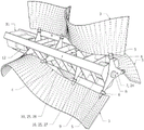
A force 1 is applied to the arcuate flexible sheet material 2 to produce a deformed corrugated strip fin 3 (which has a strain deformation) as shown in figure 1. The strain deformation takes a sinusoidal-like shape, which represents the internal energy state of the flexible sheet material 2 after it has been arranged into the corrugated strip-shaped fins 3. This strain deformation continues to be maintained after incorporation into the mechanism with the coupling 5, 6, 7, 10 (e.g. fig. 2), which prevents the accordion-like strip fin 3 from returning to its unstrained state.
In one embodiment, in its strained state, the corrugated strip fin 3 is prevented from returning to its relaxed state by being fixed to the first coupling 5 at least two locations along the inner edge 4 (the first coupling 5 being fixed to the vertebral plate 7), for example by a rotatable member 6 (the member 6 may be a bearing 6a, fig. 3), or by other members that allow transmission of force from the first coupling 5 and the vertebral plate 7 while allowing local rotation between the first coupling 5 and the vertebral plate 7, such as a flexible plate 6b (fig. 4), torsion spring, rubber bushing, or the like. The vertebral plate 7 is fixed to the shaft 8 of an actuator 9, fig. 2, such as an electromagnetic motor, a hydraulic motor, a servo mechanism, etc. The actuators may be fixed to the common member 10 and powered by a battery 11 or other power source. In one embodiment, the rotational position of the actuator 9 may be controlled by a central controller 12.
In one embodiment, the first coupling 5, the rotatable member 6, the vertebral plate 7 and the shaft 8 constitute a transmission assembly 13, fig. 3.
In one embodiment, the attachment points of the corrugated strip fin 3 to the transmission assemblies 13, 13a, 13b have three degrees of freedom of movement. The actuator 9 causes the vertebral plate 7 to rotate 14 about the axis of the shaft 8. Since the vertebral plate 7 is flexible in a direction 15 parallel to the axis of the shaft 8 in one embodiment, the end of the vertebral plate 7 where it is fixed to the rotatable part 6 can move 15 in a direction parallel to the axis of the shaft 8. The rotatable part 6 allows at least partial rotation 16, fig. 4, of the first coupling 5 about an axis 17 perpendicular to the shaft 8.
In one embodiment, the vertebral plate 7 may be rigid and movement of the drive assemblies 13, 13b in a direction 15 parallel to the axial direction of the shaft 8 may be facilitated by bearing tracks, sleeve bearings 17a, or the like, fig. 5. The transmission assemblies 13, 13b may be coupled with the common component 10 by mounting fixtures 17 b.
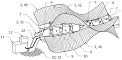
The central controller 12 causes the actuator 9 to rotate the vertebral plates 7 sequentially clockwise and counterclockwise, which causes the wave of travel to move along the corrugated, strip-shaped fins 3. When the mechanism is arranged in a fluid medium, fig. 6, the fluid moves 18 mainly in the direction of the travelling wave 19, so that the mechanism as well as the body 20 (which body 20 can be attached to the mechanism by equipping the fixture 22) travels in a direction 21 opposite to the direction of the travelling wave 19. Some examples of applications include surface or subsea vessel propulsion, propulsion of lighter-than-air vehicles, and the like.
The central controller 12 and the battery 11 or other power source may be arranged, for example, inside the common component 10, which common component 10 may be watertight or airtight in some embodiments. In one embodiment, one fin or two fins (fig. 7) or more than two fins may be attached to the common component 10 by a transmission assembly 13, 13a, 13b to create a free-swimming vessel or vehicle that can move through a fluid by applying a force to the fluid, as described above. For aircraft utilizing such embodiments, the thrust vectors may facilitate control of the pitch, yaw, roll, direction, turning, and other controllable motions of the vessel that may be performed by the central controller 12. Sensors such as accelerometers, gyroscopes, inertial measurement units, compasses, optical flow sensors, sonar, lidar and fluid motion sensors (e.g., pressure and velocity sensors, etc.) may be fed to the central controller 12 in order to achieve the desired behavior of the vessel, vehicle or structure.
In some embodiments, the mechanism shown in FIG. 7 may also be configured to move itself over land or other substrate 23, such as by adjusting the position of fins 3 to contact land or other substrate 23, and by configuring transmission assemblies 13, 13a, 13b to generate a crawling or "sliding" action by central controller 12 to move the vessel or vehicle in a desired direction, FIG. 8.
In another embodiment, the mechanism described above and shown in fig. 6 is not secured to the body 20 by the arming fixture 22, but rather is secured to the immovable object or substrate 23 by the arming fixture 22. The wave of travel 19 along the corrugated strip fins 3 caused by the transmission assembly 13, 13a, 13b may cause a fluid, such as air or water, to move 18 primarily in the direction of the wave of travel 19, fig. 9. Applications include fluid movement devices, such as fans or pumps; fluid transport or mixing, e.g., for industrial and chemical applications; aggregate, particulate or powder mixing or delivery, e.g., for industrial and chemical applications, etc.
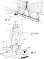
In another embodiment, the vertebral plate 7 has two or more lobes that may be evenly spaced and may be rotationally symmetric about the axis of the shaft 8. For example, in fig. 10, a tri-lobed vertebral plate 24 is shown. In this embodiment, the above-mentioned common component 10 may be a chassis-like structure 10, 25 comprising at least a main longitudinal element 10, 25, 26 and at least a main transverse element 10, 25, 27, to which at least one actuator 9 is fixed to the longitudinal element 10, 25, 26 and the transverse element 10, 25, 27. One or more actuators 9 are fixed to a chassis 25, which chassis 25 provides reaction torque for the actuators 9. The corrugated strip fin 3 is fixed to at least one angular vertebral plate 24 by a first coupling 5. In one embodiment, at least one actuator 9 is used to drive at least one angulated vertebral plate 24. In one embodiment, the central controller 12 controls the actuator 9, and a battery 11 or other power source powers the central controller 12 and the actuator 9.
In one embodiment, for the embodiment shown in fig. 10, the drive assembly 13, 28 of fig. 11 may include the first coupling 5 powered by the actuator 9, the rotatable member 6, the lobed vertebral plate 24, and the shaft 8, and may be capable of three degrees of freedom of movement.
In another embodiment, one or more equipment fixtures 22 may be added at locations on the chassis 10, 25 so that the mechanism may be secured to another body or to an immovable object or substrate 23. In embodiments where the further body 20 is a vessel such as a boat, submersible or lighter-than-air craft (fig. 12), the mechanism in operation may provide propulsive thrust in the manner shown in fig. 6. In another embodiment (fig. 13) where the body is a non-movable object or matrix 23, the mechanism in operation may move the ambient fluid in a desired direction for fluid transport purposes or for fluid, particulate, and aggregate mixing purposes in a manner similar to that shown in fig. 9.
In another embodiment, the actuator 9 is an electromagnetic and/or other transducer capable of utilizing energy. In such embodiments, when the arming fixture 22 is attached to an immovable object or substrate 23, the ambient fluid having a directional motion may cause the deformation of the corrugated strip 3 to move in a traveling wave in the direction of the fluid motion. Kinetic energy from the moving fluid is transferred to the corrugated strips 3 and may be converted to electrical energy by the actuator 9. In one embodiment, energy may be stored in the battery 11, fig. 9, 13, 14.
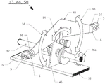
In another embodiment, the common component 10 is a chassis-like structure 29, to which chassis-like structure 29 the actuator 9 is fixed, fig. 14. In one embodiment, the chassis-like structure 29 passes continuously through the slots 30 in the vertebral plates 7, 24 to make them slotted vertebral plates 31, enabling the actuator 9 to rotate the slotted vertebral plates 31 without colliding with the chassis-like structure 29.
In one embodiment, a transmission assembly 33 (fig. 15) for this embodiment provides three degrees of freedom and may include a shaft 8 powered by an actuator 9, a first coupling 5, a rotatable member 6, and a slotted vertebral plate 31. In one embodiment, the inner region 34 of the slotted vertebral plate 31 is thicker or stiffer or wider than the region 35 closer to the attachment point of the bearing member to enable torque to be transferred from the shaft 8 while also enabling the portion 35 of the slotted vertebral plate 31 closer to the rotatable member 6 to bend and move along the axis 15 parallel to the shaft 8.
In one embodiment (fig. 16 and 19), two or more transmission assemblies 13 powered by actuators 9 and controlled by a central controller 12 may be shared by two or more corrugated strip fins 3 (fig. 19), the actuators 9 being fixed to a common part 10, powered by a battery 11 or other power source. The common component 10 is secured to an equipment fixture 22, which equipment fixture 22 is secured to a non-movable object or substrate 23 or to the body of the vessel 20 in a manner similar to that described in the above embodiments. The clockwise and anticlockwise rotation of the transmission assembly 13 can cause the sinusoidal deformations of the two corrugated strip fins 3 to travel in the same direction with each other along the axis of the shaft 8.
In another embodiment with two corrugated strip fins 3 (fig. 17 and 20), one corrugated strip fin 3, 36 is attached to one set of transmission assemblies 13, 37, while the other corrugated strip fin 3, 38 is connected to a second set of transmission assemblies 13, 39, fig. 20. This enables one corrugated strip fin 3, 36 to operate independently of the other corrugated strip fin 3, 38 under the control of the central controller 12. In one embodiment, this in turn allows the deformation of one corrugated strip fin 3, 36 to proceed in the opposite direction to the other corrugated strip fin 3, 38. The degree of rotation of the drive assemblies 13 may vary between sets of drive assemblies as well as within a set of drive assemblies. Thus, for a vessel utilizing this embodiment, thrust vectoring helps control the pitch, yaw, roll, direction, turning, and other control motions of the vessel that may be performed by the central controller 12. (e.g., FIGS. 19-21). Sensors such as accelerometers, gyroscopes, inertial measurement units, compasses, optical flow sensors, sonar, lidar and fluid motion sensors (e.g., pressure and velocity sensors) etc. may be fed into the central controller 12 to achieve the desired operation of the vessel, vehicle or mechanism.
Another embodiment utilizes two pairs of corrugated strip fins 3, fig. 18 and 21. The first pair 40 is coupled with one set of transmission assemblies 13, 37 and the second pair 42 is coupled with the second set of transmission assemblies 13, 39, fig. 21, which may allow this embodiment to apply more thrust without adding an actuator 9. For vessels utilizing this embodiment, thrust vectoring may be facilitated to control the pitch, yaw, roll, direction, turning, and other control motions of the vessel that may be performed by the central controller 12, such as described above.
In another embodiment of fig. 22-23, a single actuator 43 may be used to simultaneously drive multiple drive assemblies 13, 44 through the use of a crankshaft, scotch yoke, camshaft, or the like. An example of the use of a shaft with a conjugate cam is shown in fig. 22, and a battery or other power source 11 powers at least one actuator 43 attached to the common member 10. Two or more drive assemblies 13, 44 (fig. 23) are mounted on the common component 10 by drive assembly mounts 46. Rotation 46a of the cam shaft 47 causes the vertebral plates 7, 48 of the two or more drive assemblies 13, 44 to rotate clockwise and counter-clockwise 14 in a similar manner as described in the previous embodiments. The transmission assemblies 13, 44 are coupled with the corrugated strip fins 3 in a similar manner to that described in the previous embodiments. The common component 10 may be attached to a non-movable object or substrate 23 or to the body of the vessel 20 (fig. 22) in a similar manner and for a similar purpose as described in the above examples and embodiments.
In another embodiment, the transmission assembly 13, 44 may be coupled with two or more corrugated bar fins 3 through a lobed laminar plate 49, wherein a plurality of corrugated bar fins 3 are attached to the same lobed laminar plate 49, so as to create a lobed transmission assembly 50 with a plurality of fins attached, fig. 24. At least one cam-like drive assembly 50 mounted on the common member 10 may be driven by an actuator 43, such as an electric motor and central controller 12, and powered by a battery 11 or other power source to produce a free-swimming mechanism which may have a gear box 51 between the actuator and the cam shaft 47, fig. 25.
In another embodiment, the mechanism may be attached to the body 20 by one or more accessory fixtures 22 to provide thrust to the body 20. The body may be a subsea vessel, a surface vessel, or a body part of a person swimming or diving in the water, or the body 20 may be attached to equipment worn by the person swimming or diving, fig. 26.
In one generator embodiment, the common component 10, 25 may be secured to an equipment fixture 22, the equipment fixture 22 being secured to a non-movable object or substrate 23, fig. 27. The motive fluid 52 may exert a load on the fins 3, which may cause a strain deformation in the fins 3 to travel 54 in the direction of the motive fluid 52 to cause rotation of the shaft 47 through the transmission assembly 13, 44, 50. Shaft 47 may be rotationally coupled to a gearbox 51, which gearbox 51 is coupled to an electromagnetic generator 53 or other transducer capable of converting rotational motion into electrical energy. Power from the electromagnetic generator 53 or other transducer may be sent to the battery 11 or to the grid.
It will be appreciated that the embodiments described herein are susceptible to considerable flexibility and that the embodiments are capable of many variations, modifications, improvements and other uses and applications. All such changes, variations, modifications, and other uses and applications which do not depart from the spirit and scope of the invention are deemed to be covered by the embodiments and variations thereof described herein.
In another embodiment, arcuate vanes 55 are added to one edge of the arcuate flexible sheet of material 2, FIG. 28. The arcuate blades 55 may be fabricated, for example, from a hard, flexible material having high elasticity, such as stainless steel, hard polymers, and the like. The arcuate blade 55 may be attached, for example, to the side of one edge of the flexible sheet material 2, or it may be inserted into a slot 56 in one edge of the flexible sheet material 2, fig. 28-29. Fig. 30 shows a cross-sectional view through the edge of the flexible sheet material 2, wherein the arcuate blades 55 are inserted into the slots 56 and secured by rivets, bolts, grommets or similar attachment means 57 which pass through holes in the flexible sheet material and the arcuate blades 55. FIG. 31 shows a cross-sectional view of an embodiment in which arcuate vanes 55 have a thickened portion or flange along the edge that is inserted into slot 56, and slot 56 has a widened portion that accommodates the cross-sectional profile of arcuate vane 55 to mechanically retain arcuate vane 55 in slot 56. In addition to or instead of these mechanical means of securing the arcuate vanes 55 to the flexible sheet material 2, glue or other adhesive may be applied to secure the arcuate vanes 55 to the flexible sheet material 2.
In another embodiment of the arcuate blade 55, the outer radius edge of the arcuate blade 55 forms a continuous arc, but its inner edge includes a series of narrow tabs 58 for reducing in-plane bending loads on the arcuate blade 55 and a series of apertures 59, FIG. 32, the apertures 59 being contiguous with the arcuate blade 55. In an example of this embodiment, the coupling member 57 passing through the flexible sheet material may pass through the eyelet.
Once the arcuate blades 55 are installed in the flexible sheet material 2, one or more forces 1 are applied to the flexible sheet material 2 (to which the arcuate blades 55 are secured) to produce the deformed corrugated strip composite fin 60 having a strain deformation. In one propulsion embodiment, two or more composite fins 60 are each coupled with two or more transmission assemblies 13, 13a, 13b, the transmission assemblies 13, 13a, 13b being powered by a motor coupled with the common component 10, thereby creating a vehicle capable of "skating" on ice, fig. 33. The central controller 12 and battery 11 or other power source for powering the transmission assemblies 13a, 13b may be located within the common component 10.
In another embodiment, two or more composite fins 60 are each coupled with two or more transmission assemblies 13, 44, the transmission assemblies 13, 44 being coupled with a common component 10, 25, so as to create a vehicle that can be rolled on ice. The drive assemblies 13, 44 for each fin may be driven by a motor 43 operating a crankshaft, scotch yoke, camshaft, or the like. An example is shown in fig. 34, which uses a shaft 47 with a conjugate cam for each composite fin 60, whereby the central controller 12 and battery 11 or other power source power the motor of each composite fin 60, thereby enabling independent control of the speed and direction of undulating travel of each composite fin 60. The independent control of each composite fin 60 allows for vehicle direction change and maneuverability on ice. In an alternative embodiment, a single motor and/or coupling control for both composite fins may be provided.
In another embodiment, the vehicle may have two or more thrust modules, fig. 35-36. The thrust modules 62, 63 may comprise corrugated strip fins 3, which corrugated strip fins 3 are coupled with the common part 10 by means of transmission assemblies 13, 13a, 13b, 28, 44. In one embodiment, the common component 10 may include a cam having a cam shaft 47, the cam shaft 47 being driven, for example, by a single actuator 43 through a belt or gear or the like, to produce a cam thrust module 62 (fig. 35) having the battery 11 or other power source and the central controller 12. The common component 10 may be used to hold a plurality of actuators 9, such as servomotors, in order to make a servothrust module 63 (fig. 36), the servothrust module 63 having a battery 11 or other power source and a central controller 12, for example for autonomous or remote control operation.
In one vehicle embodiment, a rotary roll actuator 64 (e.g., an electric motor) is secured to the common component 10 at either end of the thrust modules 62, 63. The shaft or other rotating component 65 of the first roll actuator 64 is secured to one end of a flexible coupling member 66. The shaft or other rotating component 65 of the second roll actuator 64 is secured to the other end of the flexible coupling component 66, FIG. 37. Thus, in one embodiment, the first and second thrust modules 62, 63 of the vehicle may be elastically coupled to each other by the flexible coupling component 66 and by the rotational component 65 of the roll actuator 64. The central controllers 12 of the thrust modules 62, 63 may communicate with each other through a wired or wireless coupling. Each roll actuator 64 may rotate independently of the other roll actuators 64 under the control of central controller 12.
The wave motion of the fins is caused by the actuators of the thrust modules 62, 63. For example, the primary thrust vector of the thrust modules 62, 63 caused by the driving of a wave of travel along the fins 3 may generate a force in a direction substantially opposite to the wave of travel and substantially parallel to the longitudinal axis of the thrust modules 62, 63. The second, smaller thrust vector of the thrust module 62, 63 may be perpendicular to the longitudinal axis of the thrust module 62, 63.
In one embodiment, the default operating position of the vehicle may be a position in which the fins 3 are in a generally horizontal position, the thrust modules 62, 63 are substantially parallel to each other, and the flexible linkage members 66 are substantially parallel to each other. Fig. 38 shows the default operating position as viewed from the front of the vehicle, and fig. 39 shows the default position as viewed from above the vehicle. In this default position, the vehicle may travel in a straight line when the traveling wave of the fin 3 travels in the same direction. The dashed lines shown in FIG. 38 indicate the position of the forward roll actuator 64a relative to the flexible coupling 66 and indicate the position of the aft roll actuator 64b relative to the flexible coupling 66.
In various embodiments and/or modes of operation, various fin 3 tilt and fin 3 rotational positions may be implemented and/or realized to generate various thrust vector forces on the vehicle. Actuation of one or more roll actuators 64 of the vehicle enables the thrust modules 62, 63 to tilt relative to each other such that the primary thrust vectors of the two thrust modules 62, 63 are no longer parallel, thereby causing the vehicle to roll and/or change direction.
Fig. 40 shows an example, which is a view from the front of the vehicle, in which position the rotary part 65 of the left forward roll actuator 64a rotates the flexible coupling member 66 (which is fixed to the flexible coupling member 66) forty-five degrees (67) relative to itself, and the rotary part 65 of the left rearward roll actuator 64b rotates the flexible coupling member 66 (which is fixed to the flexible coupling member 66) 0 degrees relative to itself. The rotary component 65 of the right rear roll actuator 64b rotates the flexible coupling member 66 (which is fixed to the flexible coupling member 66) forty-five degrees (67) relative to itself, and the rotary component 65 of the right front roll actuator 64a rotates the flexible coupling member 66 (which is fixed to the flexible coupling member 66) 0 degrees relative to itself. Fig. 41 shows the same configuration as fig. 40 when the vehicle is viewed from above.
Another example is shown in fig. 42, which shows a view from the front of the vehicle, where the rotary part 65 of the left front roll actuator 64a rotates the flexible coupling member 66 (to which it is fixed) counterclockwise forty-five degrees (67) relative to itself, and the rotary part 65 of the right front roll actuator 64a rotates the flexible coupling member 66 (to which it is fixed 66) counterclockwise forty-five degrees (67) relative to itself. The rotational component 65 of the left aft roll actuator 64b rotates the flexible coupling 66 (which is attached to the flexible coupling 66) forty-five degrees clockwise (67) relative to itself, and the rotational component of the right aft roll actuator 64b rotates the flexible coupling 66 (which is fixed to the flexible coupling 66) 45 degrees clockwise (67) relative to itself. Fig. 43 shows the same positioning of roll actuator 64 when the vehicle is viewed from above. In this example, the thrust vector of the left thrust module 62 is angled downward, while the thrust vector of the right thrust module 62 is angled upward.
Another example is shown in fig. 44, which shows a view from the front of the vehicle, in which position the rotary part 65 of the left forward roll actuator 64a rotates the flexible coupling part 66 (to which it is fixed) 90 degrees counterclockwise (67) relative to itself, and the rotary part 65 of the right forward roll actuator 64a rotates the flexible coupling part 66 (to which it is fixed 66) 90 degrees counterclockwise (67) relative to itself. The rotational components 65 of both the left and right aft roll actuators 64b, 64b rotate the coupling member 66 (to which they are fixed to the flexible coupling member 66) 0 degrees relative to itself. In this example, the primary thrust vectors of the thrust modules 62 are angled upward and downward relative to each other and inward toward the central longitudinal axis of the vehicle. Fig. 45 shows the same positioning of the roll actuator 64 when the vehicle is viewed from above.
When one or more roll actuators 64 have caused the thrust modules 62, 63 to tilt, the distance measured horizontally between the forward and aft roll actuators 64, 64 decreases, and the flexible coupling member 66 is now out of plane, causing bending and twisting, the surfaces of the flexible coupling member 66 no longer being parallel to each other. The flexible nature of the flexible coupling members 66 allows out-of-plane bending while substantially resisting in-plane bending due to their aspect ratios.
In another embodiment, the two flexible link members 66 may be connected by a second chassis 68, the second chassis 68 may be rigid or semi-rigid, and one or more vehicle payloads may be attached to the second chassis 68, fig. 46. In one embodiment, one end of the second chassis 68 may be rigidly fixed 69 to the first flexible coupling member 66, while the other end may be rotationally coupled to the second flexible coupling member 66, for example, by a shaft and bearing 70 or other member capable of one degree of rotational freedom.
FIG. 47 illustrates an embodiment having a fairing 71 surrounding thrust modules 62, 63 and illustrates a payload 72 coupled to second chassis 68.
In various embodiments, the enhanced mobility of the vehicle may be caused by various factors. For example, these may include fast and/or near instantaneous thrust (due to their large surface area) caused by the fins 3, the fins 3 being able to cause drag vectoring in addition to thrust vectoring, and/or roll actuators enabling the fins 3 to tilt and rotate relative to the longitudinal axis of the vehicle.
Examples of rapid position and orientation changes and maneuverability in this embodiment are shown sequentially in fig. 48-52. In fig. 48, the roll actuator 64 is in a default position in one embodiment with the direction of fin undulation travel 73 directly aft, thereby causing vehicle motion 74 to be directly forward. The horizontal plane 75 is shown as a dashed line in fig. 48-52 as a reference plane to show how the position and movement of the vehicle changes in the sequence.
In fig. 49, the roll actuator 64 tilts the thrust modules 62, 63 in opposite directions, such as shown in fig. 44-45, so that the thrust vector of one fin is locally upward and the thrust vector of the other fin is locally downward. This causes the vehicle motion 74 to include a rotational component (e.g., roll) about the longitudinal axis of the vehicle as it travels forward. Fig. 50 shows the vehicle after this rotation about the vehicle longitudinal axis, rotating the horizontal plane of the vehicle 90 degrees, and the roll actuators 64 returning to their default positions. In fig. 51, the undulations 73 of the upper fin 3 travel rearwardly while the undulations 73 of the lower fin travel forwardly, so that the vehicle motion 74 includes a rotational component (e.g., yaw) about the lateral axis of the vehicle. In fig. 52, the vehicle has completed the 90 degree turn and the undulations 73 of both fins travel rearwardly (now upwardly in the figure) causing the vehicle to move 74 directly downwardly. In this way, according to the embodiment, a vehicle traveling horizontally forward can quickly roll and pitch directly downward.
To address various issues and advance the art, the entire contents of this application (including covers, titles, headings, areas, background, summary, brief description of the drawings, detailed description, claims, abstract, drawings, appendix, etc.) of the "vehicle with traveling wave thrust module apparatus", illustrates by way of illustration various embodiments in which the claimed innovations may be made, arranged and/or implemented. The advantages and features of the present application are merely representative of the embodiments and are not intended to be exhaustive and/or exclusive. They are presented merely to assist in understanding and teaching the principles of the claims. It should be understood that they do not represent all of the claimed innovations. Accordingly, certain aspects of the disclosure are not discussed herein. That alternate embodiments may not have been presented for a specific portion of the innovation, or that further alternate embodiments may be presented for a portion, is not to be considered a disclaimer of those alternate embodiments. It should be understood that many of these undescribed embodiments contain the same principles of innovation, and other embodiments are equivalent. It is therefore to be understood that other embodiments may be utilized and that functional, logical, operational, organizational, structural and/or topological changes may be made without departing from the scope and/or spirit of the present invention. Accordingly, all examples and/or embodiments are to be considered in a non-limiting sense throughout this disclosure. Also, except for the purpose of reducing space and repetition, reference should not be made to those embodiments described herein with respect to those not described herein. For example, it should be understood that the logic and/or topology of any combination of any set of process steps and/or features described in the figures and/or throughout is not limited to a fixed order and/or arrangement of operations, but rather that any disclosed order is exemplary and that the invention contemplates all equivalents regardless of order. Similarly, some features apply to one aspect of the innovation, but not to others. Additionally, the present invention encompasses multiple innovations, including some that may not be presently claimed, and the applicant reserves all rights in those innovations presently claimed, including the rights to claim such innovations, file additional applications, continuation-in-part, divisional, etc. Accordingly, it should be understood that advantages, embodiments, examples, functions, features, logic, operations, organizations, structures, topologies, and/or other aspects of the present invention should not be considered limitations on the invention as determined by the claims or limitations on equivalents to the claims.