Disclosure of Invention
The invention aims to provide a beverage capsule brewing device and a capsule coffee machine, which can automatically discharge capsules after brewing, and simultaneously have a more compact integral structure and are beneficial to miniaturization development.
The invention provides a beverage capsule brewing device, which comprises a shell, a brewing seat arranged in the shell and a pressing mechanism, wherein the pressing mechanism can move relative to the brewing seat, a brewing cavity is arranged in the brewing seat, an avoiding space is formed between the outer side of the brewing seat and the inner side wall of the shell, the pressing mechanism is provided with a clamping mechanism for clamping a beverage capsule, and in the process that the pressing mechanism moves towards the direction close to the brewing seat, the clamping mechanism is pushed open by the beverage capsule when the beverage capsule enters the brewing cavity, so that the clamping mechanism loosens the beverage capsule and enters the avoiding space.
In some embodiments, the holding mechanism comprises holding pieces respectively arranged at two sides of the pressing mechanism, the holding pieces are connected with a reset mechanism, the reset mechanism is fixedly connected with the pressing mechanism, and the holding pieces are reset under the control of the reset mechanism.
In some embodiments, the reset mechanism includes a connecting member and a reset member, the connecting member is fixed on the compressing mechanism, and two ends of the reset member respectively abut against the connecting member and the compressing mechanism.
In some embodiments, a plug connector is convexly arranged on the outer side of the pressing mechanism, a slot is arranged in the plug connector, the two ends of the connecting member are respectively a first end and a second end, the first end is fixedly connected with the clamping member, and the second end is inserted into the slot.
In some embodiments, two ends of the reset piece respectively abut against the second end and an inner side wall of the slot away from the pressing mechanism.
In some embodiments, a groove is formed in an inner side wall, away from the pressing mechanism, of the slot, and one end, away from the connecting piece, of the resetting piece abuts against the groove.
In some embodiments, the resetting member is configured as a first clamping member, an included angle is formed between the length direction of the first clamping member and the length direction of the connecting member, and one end of the first clamping member, which is far away from the connecting member, is clamped in the groove.
In some embodiments, a mounting groove is formed in one side of the retaining member away from the axis of the pressing mechanism, and the first end is located in the mounting groove and detachably connected with the retaining member.
In some embodiments, a guide groove and a lifting piece are arranged on one side of the holding piece close to the axis of the pressing mechanism, and the lifting piece is positioned below the guide groove.
In some embodiments, a side wall of the guide groove close to the pressing mechanism is connected with a second clamping piece, and during the process that the pressing mechanism moves to the direction far away from the brewing base, the side of the second clamping piece far away from the guide groove can abut against the convex edge of the beverage capsule.
In some embodiments, a side of the second card member near the axial center of the hold-down mechanism is provided with an inclined portion that is inclined from a direction away from the guide groove toward a direction near the guide groove.
In some embodiments, a limiting member protrudes from a side of the retaining member away from the axial center of the pressing mechanism, and a guide member is disposed on an inner side wall of the housing, and during the movement of the pressing mechanism relative to the brewing base, a side of the limiting member away from the axial center of the pressing mechanism can abut against the guide member.
In some embodiments, the length directions of the limiting member and the guiding member are perpendicular to each other.
A second aspect of the invention provides a coffee capsule machine comprising water supply means and a beverage capsule brewing apparatus as described in the first aspect; the water supply device is communicated with the beverage capsule brewing device and provides water source for the beverage capsule brewing device, and the beverage capsule is a coffee capsule.
The beverage capsule brewing device and the capsule coffee machine provided by the invention have the beneficial effects that in the process that the pressing mechanism moves towards the direction close to the brewing base, the clamping mechanism is pushed open by the beverage capsule when the beverage capsule enters the brewing cavity so that the clamping mechanism loosens the beverage capsule and enters the avoiding space, the clamping mechanism resets after loosening the beverage capsule, so that in the process that the pressing mechanism moves towards the direction far away from the brewing base after brewing, the clamping mechanism drags the beverage capsule out of the brewing cavity and automatically drops the beverage capsule, the capsule can be automatically discharged after brewing, the automatic bag dropping is realized, the operation is convenient, meanwhile, shoulders for pushing open the clamping mechanism are not required to be arranged at two sides of the brewing cavity, only the avoiding space is reserved for the clamping mechanism, the occupied space of the brewing base can be reduced, the radial size of the shell is reduced, and the overall structure is more compact, is beneficial to the miniaturization development.
Detailed Description
In order to facilitate an understanding of the invention, specific embodiments thereof will be described in more detail below with reference to the accompanying drawings.
As used herein, unless otherwise specified or defined, "first" and "second" … are used merely to distinguish between names and do not denote a particular quantity or order.
As used herein, the term "and/or" includes any and all combinations of one or more of the associated listed items, unless specified or otherwise defined.
It should be noted that "fixed to" or "connected to" in this document may be directly fixed to or connected to one element or may be indirectly fixed to or connected to one element.
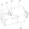
As shown in fig. 1 to 5, the embodiment of the invention discloses a beverage capsule brewing apparatus 100, which comprises a housing 10, a brewing base 20 disposed in the housing 10, and a pressing mechanism 30, wherein the pressing mechanism 30 is movable relative to the brewing base 20, a brewing cavity 21 is disposed in the brewing base 20, an avoiding space is formed between the outer side of the brewing base 20 and the inner side wall of the housing 10, and the pressing mechanism 30 is provided with a holding mechanism for holding a beverage capsule 200 (hereinafter referred to as capsule).
Wherein, the capsule can be filled with beverage solutes such as coffee powder, bean powder or milk powder, and the corresponding beverage capsule brewing device 100 is suitable for brewing and making beverages such as coffee, soybean milk or milk. The brewing base 20 and the pressing mechanism 30 are horizontally arranged in the horizontal direction, so that the pressing mechanism 30 can move back and forth relative to the brewing base 20 in the horizontal direction. The power source for the horizontal movement of the pressing mechanism 30 may be a plurality of manners such as hinge structure control, motor driving control, etc., and here, the hydraulic control movement manner is preferably used.
The capsule holding space is arranged in the shell 10 and is positioned between the brewing base 20 and the pressing mechanism 30, the top of the shell 10 is provided with a capsule inlet, the bottom of the shell 10 is correspondingly provided with a capsule outlet, the capsule inlet and the capsule outlet are respectively communicated with the capsule holding space, the clamping mechanism is normally positioned in the capsule holding space, before brewing, the capsule is firstly placed into the capsule holding space from the capsule inlet, and the capsule is clamped at the clamping part of the clamping mechanism and can be driven by the clamping mechanism to move along with the pressing mechanism 30. The clamping mechanism is provided with a clamping part and a falling part.
In the process that the hold-down mechanism 30 moves towards the direction close to the brewing base 20, the clamping mechanism is pushed open by the capsule when the capsule 200 enters the brewing cavity 21 so that the clamping mechanism loosens the capsule and enters the avoiding space, the clamping mechanism resets after loosening the capsule, so that in the process that the hold-down mechanism 30 moves towards the direction far away from the brewing base 20 after brewing, the clamping mechanism contacts with the capsule again, the capsule is positioned at the falling part of the clamping mechanism and is dragged out of the brewing cavity 21 by the clamping mechanism, when the capsule is dragged back to the capsule containing space, the capsule automatically falls from the capsule outlet due to the self gravity, so that the capsule can be automatically discharged after brewing, automatic bag falling is realized, the operation is convenient, meanwhile, shoulders for pushing open the clamping mechanism are not required to be arranged at the two sides of the brewing cavity 21, only the avoiding space is reserved for avoiding the clamping mechanism, and the occupied space of the brewing base 20 can be reduced, so as to reduce the radial dimension of the shell 10, and further make the whole structure more compact, which is beneficial to the miniaturization development.
In addition, compared to the prior art solution in which the two sides of the brewing chamber 21 are provided with protruding shoulders, the retention mechanism cooperates with the two parts of the shoulders, and the retention mechanism just reaches the shoulders and is pushed open by the shoulders when the capsule 200 enters the brewing chamber 21. In the invention, the clamped capsule is used for ejecting the clamping mechanism, so that the clamping mechanism can be ensured to be ejected when the capsule 200 enters the brewing cavity 21, thereby avoiding the situation that any one of two parts which need to be matched is loosened, for example, the clamping mechanism movably connected with the pressing mechanism 30 is loosened, so that the clamping mechanism can not reach the shoulder when the capsule 200 enters the brewing cavity 21, and further improving the transmission performance.
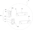
Wherein, the holding mechanism comprises holding pieces 40 respectively arranged at both sides of the pressing mechanism 30, the holding pieces 40 are normally positioned in the capsule containing space, and the connecting line between the holding pieces 40 at both sides and the connecting line between the capsule inlet and the capsule outlet are arranged perpendicular to each other. The holding member 40 is connected with a reset mechanism which is fixedly connected with the pressing mechanism 30, and the holding member 40 is controlled by the reset mechanism to reset after the capsule is loosened.
In this embodiment, the reset mechanism includes the connecting piece and resets on, the connecting piece is fixed in hold-down mechanism 30, resets both ends of piece respectively the butt in connecting piece and hold-down mechanism 30, and the connecting piece plays elastic deformation's effect, and resets and play the effect that causes connecting piece elasticity to reset. Preferably, the connecting member is provided as a spring plate 50, and the spring plate 50 is a thin steel plate and is fixedly clamped on the pressing mechanism 30. The outer side of the pressing mechanism 30 is provided with a plug connector 31 in a protruding manner, a slot 311 is arranged in the plug connector 31, two ends of the springboard 50 are respectively a first end and a second end, the first end is fixedly connected with the clamping member 40, and the second end is inserted into the slot 311.
In this embodiment, two ends of the reset element respectively abut against the second end and the inner side wall of the slot 311 far away from the pressing mechanism 30. When the holding member 40 is forced by the capsule to be ejected, the elastic plate 50 is driven to move in a direction close to the reset member (i.e. opposite to the clamping direction), and the reset member abuts against the inner side wall of the slot 311 far away from the pressing mechanism 30, so as to generate an inward acting force on the elastic plate 50, so that the elastic plate 50 is reset by the action force of the reset member after the holding member 40 is ejected. The inner side wall of the slot 311 away from the pressing mechanism 30 is provided with a groove 312, an installation space is reserved for the reset element, and one end of the reset element away from the connecting element abuts against the groove 312.
In other possible embodiments, the restoring member may be an elastic member, such as a spring, the length direction of the spring is perpendicular to the length of the elastic plate 50, and two ends of the spring abut against the elastic plate 50 and the groove 312, respectively. In this embodiment, the resetting member is configured as a first latch 60, an included angle is formed between the length direction of the first latch 60 and the length direction of the elastic plate 50, and one end of the first latch 60 away from the elastic plate 50 is clamped in the groove 312. When the holding member 40 is subjected to the capsule ejecting force, the elastic plate 50 is deformed outward to release the capsule, and after the elastic plate 50 releases the capsule, the elastic plate 50 is restored. Wherein, preferably, the first clip 60 is integrally formed with the spring plate 50.
In this embodiment, a mounting groove 41 is formed on a side of the retaining member 40 away from the axial center of the pressing mechanism 30, and the first end is located in the mounting groove 41 and detachably connected to the retaining member 40. Wherein, the size of mounting groove 41 and the size phase-match of first end, the bottom protrusion of mounting groove 41 is provided with fixture block 411, and first end is provided with spacing groove 51, and spacing groove 51 and fixture block 411 phase-match realize that first end just blocks to locate in mounting groove 41. Alternatively, in some other possible embodiments, the first end of the connecting member may be mounted in the mounting groove 41 by screws.
In this embodiment, a guide groove 42 and a lifting member are provided on one side of the holding member 40 close to the axial center of the pressing mechanism 30, the lifting member is located below the guide groove 42, and the lifting member is preferably provided as a supporting table 43. The width of the guide groove 42 is matched with the size of the convex edge of the capsule, and the guide groove 42 is used for guiding the capsule to be put in when the capsule is put in. The distance between the pallets 43 on both sides of the hold-down mechanism 30 is smaller than the radial dimension of the convex edge of the capsule and smaller than the distance between the side walls of the guide grooves 42 on both sides, and the pallets 43 are placed at the bottom of the guide grooves 42 for fixing the capsule.
In this embodiment, a side wall of the guide groove 42 close to the pressing mechanism 30 is connected with a second clamping piece 44, when viewed from the axial direction of the pressing mechanism 30, the distance between the second clamping pieces 44 at both sides of the pressing mechanism 30 is smaller than the radial dimension of the convex edge of the capsule, and a side surface of the second clamping piece 44 away from the guide groove 42 is a degummed capsule surface 441. During the movement of the pressing mechanism 30 away from the brewing base 20, the degummed surface 441 can abut against the convex edge of the capsule, thereby pulling the capsule over the outlet of the capsule.
In this embodiment, the second hook 44 is provided with an inclined portion 442 on a side closer to the axial center of the pressing mechanism 30, and the inclined portion 442 is inclined in a direction from a position away from the guide groove 42 to a position closer to the guide groove 42. When the pressing mechanism 30 continues to move forward after moving the capsule delivered to the brewing chamber 21, the convex edge of the capsule comes into abutment with the inclined portion 442 and pushes open the inclined portion 442, causing the elastic plate 50 to deform outwardly.
In this embodiment, a pressing base 70 is further provided, the pressing mechanism 30 is fixed in the housing 10 through the pressing base 70, and the pressing base 70 is disposed opposite to the brewing base 20. For the convenience of installation, the housing 10 includes two brackets 11, symmetrical avoiding grooves are formed on the two brackets 11, when the two brackets 11 are spliced together, the symmetrical avoiding grooves form a capsule inlet and a capsule outlet, and the pressing seat 70 and the brewing seat 20 are fixedly connected with the two brackets 11 through fasteners, such as screws, respectively.
In this embodiment, the retaining member 40 is provided with a limiting member 45 protruding from a side thereof away from the axial center of the pressing mechanism 30, the inner side walls of the two brackets 11 are provided with the guide members 12, and the guide members 12 are normally located between the pressing mechanism 30 and the brewing base 20, i.e. located in the capsule accommodating space. The length direction of the limiting member 45 is the same as the length direction of the guide groove 42, and the length direction of the guide 12 is the same as the axial center direction of the pressing mechanism 30, that is, the length directions of the limiting member 45 and the guide 12 are perpendicular to each other. In the process that the holding member 40 moves along with the pressing mechanism 30 relative to the brewing base 20, especially when the holding member 40 is located in the capsule accommodating space and moves along with the pressing mechanism 30 relative to the brewing base 20, one side of the limiting member 45 away from the axis of the pressing mechanism can abut against one side of the guide member 12 close to the axis of the pressing mechanism.
Preferably, the retaining member 45 and the guide member 12 are each shaped as a rib. The limiting ribs are arranged on the outer side of the clamping part 40 and are matched with the guide ribs on the inner side wall of the bracket 11, so that acting force towards the clamping direction can be applied to the clamping part 40, and therefore, in the process that the pressing mechanism 30 moves towards the direction close to the brewing base 20, the effect of further stabilizing and clamping the capsule can be achieved, and the clamping part 40 is prevented from deforming outwards to loosen the capsule before the beverage capsule enters the brewing cavity; in the process that the pressing mechanism 30 moves away from the brewing base 20, the degummed capsule surface 441 is continuously abutted with the convex edge of the capsule until the pressing mechanism 30 is reset, so that the elastic plate 50 can be completely reset to carry out the manufacture of the next cycle.
The limiting member 45 and the mounting groove 41, which are located on the side of the holding member 40 away from the axial center of the pressing mechanism 30, may be arranged in parallel or in a crossed manner. In the present embodiment, it is preferable that the mounting groove 41 is provided in a cross manner, and the stopper 45 is divided into two sections by the mounting groove 41 and is located at both side positions of the mounting groove 41. It should be noted that the position-limiting member 45 should be protruded from the top cover of the mounting groove 41, so that the fit between the position-limiting member 45 and the guide member 12 is not affected. Two guide members 12 are provided on the inner sidewall of each bracket 11 corresponding to the two segments of the position-limiting members 45.
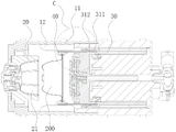
Wherein, the bottom of the brewing cavity 21 is provided with an outlet piercing plate 22 and an outlet piercing needle 23, a piercing through groove is arranged in the outlet piercing plate 22, the outlet piercing needle 23 is positioned in the piercing through groove, and the outlet piercing needle 23 is elastically connected with the bottom of the brewing cavity 21, so that the outlet piercing needle 23 can move back and forth relative to the outlet piercing plate 22 in the axial direction of the pressing mechanism 30. During the movement of the pressing means 30 towards the brewing seat 20, the capsule does not move inwards any more when it touches the outlet piercing plate 22.
Correspondingly, the side of the pressing mechanism 30 close to the brewing base 20 is provided with an inlet piercing plate 32 and inlet piercing needles 33, and the inlet piercing needles 33 are fixed to the side of the inlet piercing plate 32 close to the brewing base 20. Typically, one outlet piercing plate 22 is provided and a plurality of inlet piercing pins 33 are provided.
In addition, the pressing mechanism 30 is further provided with an elastic push plate 34, the elastic push plate 34 is positioned on one side of the inlet piercing plate 32 close to the brewing base 20, the elastic push plate 34 is provided with a piercing avoiding groove, and the inlet piercing needle 33 penetrates through the piercing avoiding groove. The resilient pusher plate 34 is movable relative to the inlet piercing plate 32 in a direction towards the brew chamber 20. Wherein, the elastic push plate 34 is provided with a support rod near the axial center, the support rod penetrates through the inlet piercing plate 32, and the support rod is fixedly connected with the hold-down mechanism 30 through a push plate spring 35. The elastic push plate 34 and the inlet piercing plate 32 are also sleeved with a sealing ring 36 for contacting the capsule 200 to form a high-pressure sealing state, so as to ensure the sealing effect in the brewing process.
Taking brewed coffee as an example, the brewing process of the beverage capsule brewing device is as follows:
as shown in FIGS. 6 and 8, the convex edge of the capsule 200 smoothly drops onto the holder 43 through the guide groove 42, and the convex edge of the capsule 200 drops onto the upper end surface of the holder 43, so that the capsule 200 is fixed to the axial center of the beverage capsule brewing apparatus.
As shown in figure 9, the pressing mechanism 30 starts to move towards the brewing base 20, and during the movement, the holding member 40 is moved, thereby moving the capsule 200 towards the brewing base 20.
During the movement, the capsule 200 is fed into the brewing chamber 21, when the bottom of the capsule 200 contacts the outlet piercing plate 22, the capsule 200 is pressed by the outlet piercing plate 22, the capsule 200 does not move into the brewing chamber 21 any more, but the pressing mechanism 30 continues to move forward, at this time, the convex edge of the capsule 200 forcibly props up the inclined portion 442 of the second clamping member 44, so that the elastic plate 50 deforms outward, when the pressing mechanism 30 continues to move forward, the convex edge of the capsule 200 enters a clearance area along the axial direction of the pressing mechanism 30 along with the inclined portion 442 separating from the guide groove 42, and after the capsule 200 separates from the guide groove 42, the elastic plate 50 resets to drive the clamping member 40 to reset.
As shown in fig. 10, the pressing mechanism 30 continues to move, the sealing ring 36 contacts with the capsule 200 to form a high-pressure sealing state, and during the movement, the elastic push plate 34 moves backwards, the push plate spring 35 is compressed, and the inlet piercing needle 33 and the outlet piercing needle 23 pierce the capsule 200 to brew the beverage. Wherein the inlet piercing needle 33 inputs hot water into the capsule 200 to brew coffee powder in the capsule 200 into coffee, which is discharged by the outlet piercing needle 23.
As shown in fig. 11 to 14, after the beverage is boiled, the pressing mechanism 30 moves away from the brewing base 20 to drive the holding member 40 to move backward, the push plate spring 35 resets, the elastic push plate 34 moves forward to push the capsule 200 to disengage from the inlet piercing needle 33, at this time, the elastic plate 50 is in a reset state, the degummed capsule surface 441 contacts with the convex edge of the capsule 200, the capsule 200 is slowly pulled out to disengage from the brewing chamber 21 during the backward movement of the pressing mechanism 30, and when the capsule 200 is completely disengaged from the brewing, the capsule 200 falls out by gravity and falls into a recovery container in the coffee machine, thereby completing the automatic bag falling process.
The embodiment of the invention also discloses a capsule coffee machine, which comprises a water supply device and the beverage capsule brewing device; wherein the water supply is in communication with and provides a source of water for the beverage capsule brewing device, and the capsule 200 is a coffee capsule. Furthermore, the water supply device comprises a water path device and a heating device, and water arranged in the water path device is heated by the heating device and then is supplied to the beverage capsule brewing device so as to brew the coffee powder in the coffee capsule.
By adopting the beverage capsule brewing device as a core component, the beverage capsule brewing device completes a series of motion conversion in the machine so as to realize the brewing process of one cup of coffee. The capsule 200 can be automatically dropped in the machine after brewing, the operation steps of a user are reduced, the operation is simple and convenient, the use is convenient for the user, shoulders for jacking the clamping mechanism are not required to be arranged on two sides of the brewing cavity 21, and only the avoidance space is reserved for avoiding the clamping mechanism, so that the occupied space of the brewing seat 20 can be reduced, the radial size of the shell 10 is reduced, the integral structure is more compact, and the miniaturization development is facilitated. It is also ensured that the catch mechanism is pushed open when the capsule 200 enters the brewing chamber 21, so that the situation that the catch mechanism cannot just reach the shoulder when the capsule 200 enters the brewing chamber 21 is avoided, and the transmission performance is improved.
The above examples are not intended to be exhaustive of the invention and there may be many other embodiments not listed. Any alterations and modifications without departing from the spirit of the invention are within the scope of the invention.