CN115031286A - Energy-saving equipment for hotel and use method - Google Patents
Energy-saving equipment for hotel and use method Download PDFInfo
- Publication number
- CN115031286A CN115031286A CN202111677005.4A CN202111677005A CN115031286A CN 115031286 A CN115031286 A CN 115031286A CN 202111677005 A CN202111677005 A CN 202111677005A CN 115031286 A CN115031286 A CN 115031286A
- Authority
- CN
- China
- Prior art keywords
- rotating rod
- heating
- water
- bin
- rod
- Prior art date
- Legal status (The legal status is an assumption and is not a legal conclusion. Google has not performed a legal analysis and makes no representation as to the accuracy of the status listed.)
- Pending
Links
- 238000000034 method Methods 0.000 title claims abstract description 20
- XLYOFNOQVPJJNP-UHFFFAOYSA-N water Substances O XLYOFNOQVPJJNP-UHFFFAOYSA-N 0.000 claims abstract description 159
- 238000010438 heat treatment Methods 0.000 claims abstract description 79
- OKTJSMMVPCPJKN-UHFFFAOYSA-N Carbon Chemical compound [C] OKTJSMMVPCPJKN-UHFFFAOYSA-N 0.000 claims abstract description 78
- 238000004140 cleaning Methods 0.000 claims abstract description 41
- 238000007789 sealing Methods 0.000 claims abstract description 37
- 238000001914 filtration Methods 0.000 claims abstract description 20
- 239000010865 sewage Substances 0.000 claims abstract description 20
- 239000002184 metal Substances 0.000 claims description 24
- 238000003825 pressing Methods 0.000 claims description 12
- 238000009434 installation Methods 0.000 claims description 11
- 239000002699 waste material Substances 0.000 claims description 6
- 238000005086 pumping Methods 0.000 claims description 4
- 238000005406 washing Methods 0.000 claims description 4
- 239000007788 liquid Substances 0.000 claims description 3
- 238000004064 recycling Methods 0.000 claims description 3
- 229910052799 carbon Inorganic materials 0.000 claims 10
- 241001233242 Lontra Species 0.000 claims 4
- 230000000712 assembly Effects 0.000 claims 1
- 238000000429 assembly Methods 0.000 claims 1
- 230000000903 blocking effect Effects 0.000 claims 1
- 238000004134 energy conservation Methods 0.000 claims 1
- 230000000694 effects Effects 0.000 abstract description 7
- 239000012535 impurity Substances 0.000 abstract description 2
- 238000009298 carbon filtering Methods 0.000 abstract 2
- 125000004122 cyclic group Chemical group 0.000 abstract 1
- 238000004321 preservation Methods 0.000 description 5
- 238000011010 flushing procedure Methods 0.000 description 3
- 239000000463 material Substances 0.000 description 3
- 230000007423 decrease Effects 0.000 description 2
- 238000013461 design Methods 0.000 description 2
- 230000007774 longterm Effects 0.000 description 2
- 238000012552 review Methods 0.000 description 2
- 238000007790 scraping Methods 0.000 description 2
- 238000013020 steam cleaning Methods 0.000 description 2
- 238000013459 approach Methods 0.000 description 1
- 238000011001 backwashing Methods 0.000 description 1
- 230000009286 beneficial effect Effects 0.000 description 1
- 230000006835 compression Effects 0.000 description 1
- 238000007906 compression Methods 0.000 description 1
- 238000001816 cooling Methods 0.000 description 1
- 238000011161 development Methods 0.000 description 1
- 238000010586 diagram Methods 0.000 description 1
- 238000005516 engineering process Methods 0.000 description 1
- 238000007667 floating Methods 0.000 description 1
Images


Classifications
-
- F—MECHANICAL ENGINEERING; LIGHTING; HEATING; WEAPONS; BLASTING
- F24—HEATING; RANGES; VENTILATING
- F24D—DOMESTIC- OR SPACE-HEATING SYSTEMS, e.g. CENTRAL HEATING SYSTEMS; DOMESTIC HOT-WATER SUPPLY SYSTEMS; ELEMENTS OR COMPONENTS THEREFOR
- F24D17/00—Domestic hot-water supply systems
- F24D17/0005—Domestic hot-water supply systems using recuperation of waste heat
- F24D17/001—Domestic hot-water supply systems using recuperation of waste heat with accumulation of heated water
-
- C—CHEMISTRY; METALLURGY
- C02—TREATMENT OF WATER, WASTE WATER, SEWAGE, OR SLUDGE
- C02F—TREATMENT OF WATER, WASTE WATER, SEWAGE, OR SLUDGE
- C02F1/00—Treatment of water, waste water, or sewage
- C02F1/001—Processes for the treatment of water whereby the filtration technique is of importance
- C02F1/004—Processes for the treatment of water whereby the filtration technique is of importance using large scale industrial sized filters
-
- C—CHEMISTRY; METALLURGY
- C02—TREATMENT OF WATER, WASTE WATER, SEWAGE, OR SLUDGE
- C02F—TREATMENT OF WATER, WASTE WATER, SEWAGE, OR SLUDGE
- C02F1/00—Treatment of water, waste water, or sewage
- C02F1/28—Treatment of water, waste water, or sewage by sorption
- C02F1/283—Treatment of water, waste water, or sewage by sorption using coal, charred products, or inorganic mixtures containing them
-
- C—CHEMISTRY; METALLURGY
- C02—TREATMENT OF WATER, WASTE WATER, SEWAGE, OR SLUDGE
- C02F—TREATMENT OF WATER, WASTE WATER, SEWAGE, OR SLUDGE
- C02F9/00—Multistage treatment of water, waste water or sewage
-
- F—MECHANICAL ENGINEERING; LIGHTING; HEATING; WEAPONS; BLASTING
- F24—HEATING; RANGES; VENTILATING
- F24D—DOMESTIC- OR SPACE-HEATING SYSTEMS, e.g. CENTRAL HEATING SYSTEMS; DOMESTIC HOT-WATER SUPPLY SYSTEMS; ELEMENTS OR COMPONENTS THEREFOR
- F24D19/00—Details
- F24D19/0092—Devices for preventing or removing corrosion, slime or scale
-
- F—MECHANICAL ENGINEERING; LIGHTING; HEATING; WEAPONS; BLASTING
- F24—HEATING; RANGES; VENTILATING
- F24D—DOMESTIC- OR SPACE-HEATING SYSTEMS, e.g. CENTRAL HEATING SYSTEMS; DOMESTIC HOT-WATER SUPPLY SYSTEMS; ELEMENTS OR COMPONENTS THEREFOR
- F24D19/00—Details
- F24D19/08—Arrangements for drainage, venting or aerating
- F24D19/082—Arrangements for drainage, venting or aerating for water heating systems
- F24D19/088—Draining arrangements
-
- Y—GENERAL TAGGING OF NEW TECHNOLOGICAL DEVELOPMENTS; GENERAL TAGGING OF CROSS-SECTIONAL TECHNOLOGIES SPANNING OVER SEVERAL SECTIONS OF THE IPC; TECHNICAL SUBJECTS COVERED BY FORMER USPC CROSS-REFERENCE ART COLLECTIONS [XRACs] AND DIGESTS
- Y02—TECHNOLOGIES OR APPLICATIONS FOR MITIGATION OR ADAPTATION AGAINST CLIMATE CHANGE
- Y02B—CLIMATE CHANGE MITIGATION TECHNOLOGIES RELATED TO BUILDINGS, e.g. HOUSING, HOUSE APPLIANCES OR RELATED END-USER APPLICATIONS
- Y02B30/00—Energy efficient heating, ventilation or air conditioning [HVAC]
- Y02B30/18—Domestic hot-water supply systems using recuperated or waste heat
Landscapes
- Engineering & Computer Science (AREA)
- Chemical & Material Sciences (AREA)
- General Engineering & Computer Science (AREA)
- Thermal Sciences (AREA)
- Combustion & Propulsion (AREA)
- Mechanical Engineering (AREA)
- Physics & Mathematics (AREA)
- Life Sciences & Earth Sciences (AREA)
- Hydrology & Water Resources (AREA)
- Environmental & Geological Engineering (AREA)
- Water Supply & Treatment (AREA)
- Organic Chemistry (AREA)
- Filtration Of Liquid (AREA)
Abstract
Description
技术领域technical field
本发明涉及酒店节能设备技术领域,具体为一种用于酒店的节能设备及使用方法。The invention relates to the technical field of hotel energy-saving equipment, in particular to an energy-saving equipment used in hotels and a method of using the same.
背景技术Background technique
在酒店,各个设备需要高温热源,而通常都采用热水或者蒸汽做热源的方式,随着社会发展和生活水平的提高,热源供应系统在住宅、酒店、办公、洗浴中心、会所等场所广泛使用,以热水作为热媒的供热系统称为热水供热设备,热水供热设备的热能利用率较高,输送时无效损失较小,散热设备不易腐蚀,使用周期长,并且散热设备表面温度较低,符合卫生要求。In hotels, each equipment requires a high-temperature heat source, and hot water or steam is usually used as the heat source. With the development of society and the improvement of living standards, the heat source supply system is widely used in residences, hotels, offices, bath centers, clubs and other places. , The heating system with hot water as the heat medium is called hot water heating equipment. The hot water heating equipment has a high thermal energy utilization rate, less ineffective loss during transportation, and the cooling equipment is not easy to corrode, has a long service life, and has a long service life. The surface temperature is low and meets the hygienic requirements.
当前的酒店热水供热设备在使用时:现有的酒店热水供热设备在长久使用时,其内壁会堆积较多热水结垢,而其采取的清理方式往往是通过蒸汽清扫或反冲洗等方式进行清理的,该种清洁方式效果较差,操作复查,耗时长,人力物力投资较大,从而增加了该热水供热设备清理的繁琐性;现有热水供热设备在使用清水冲洗时,其清洁完成的污水多数是直接排除至室外的,而其直接的排除,会增加清水的消耗,增加了清水资源的浪费现象,不便于经常采用清理;现有热水供热设备其内部结构较为单一,在对供热设备清理完成后的污水进行过滤时,多数是使用单一的过滤网板,长久使用会导致污水内部含有的结垢堵塞过滤网板,降低过滤效果,从而降低了过滤网板的使用寿命。When the current hotel hot water heating equipment is in use: when the existing hotel hot water heating equipment is used for a long time, there will be a lot of hot water scaling on the inner wall, and the cleaning method is often through steam cleaning or reverse cleaning. If the cleaning method is carried out by washing, the effect of this cleaning method is poor, the operation review is time-consuming, and the investment in manpower and material resources is large, which increases the tediousness of cleaning the hot water heating equipment; the existing hot water heating equipment is in use When rinsing with clean water, most of the cleaned sewage is directly discharged to the outside, and its direct removal will increase the consumption of clean water and increase the waste of clean water resources, which is not convenient for frequent cleaning; the existing hot water heating equipment Its internal structure is relatively simple. When filtering the sewage after the cleaning of the heating equipment, most of them use a single filter screen plate. Long-term use will cause the scale contained in the sewage to block the filter screen plate, reducing the filtering effect, thereby reducing the prolongs the life of the filter plate.
发明内容SUMMARY OF THE INVENTION
本发明的目的在于提供一种用于酒店的节能设备及使用方法,以解决上述背景技术中提出的酒店热水供热设备在使用时:多数是通过蒸汽清扫或反冲洗等方式进行清理的,该种清洁方式效果较差,操作复查,耗时长,人力物力投资较大;现有热水供热设备在使用清水冲洗时,会增加清水的消耗,增加了清水资源的浪费现象,不便于经常采用清理;现有热水供热设备其内部结构较为单一,在对供热设备多数是使用单一过滤网板对污水进行过滤工作的,长久使用会堵塞过滤网板,降低过滤效果的相关问题。The purpose of the present invention is to provide a kind of energy-saving equipment for hotels and a method of use, to solve the problem that the hotel hot water heating equipment proposed in the above-mentioned background technology is used: most of them are cleaned by steam cleaning or backwashing, etc., This cleaning method has poor effect, operation review, time-consuming, and large investment in manpower and material resources; when the existing hot water heating equipment is rinsed with clean water, it will increase the consumption of clean water and increase the waste of clean water resources, which is inconvenient to frequently Cleaning is adopted; the internal structure of the existing hot water heating equipment is relatively simple, and most of the heating equipment uses a single filter screen plate to filter the sewage. Long-term use will block the filter screen plate and reduce the related problems of the filtering effect.
为实现上述目的,本发明提供如下技术方案:一种用于酒店的节能设备及使用方法,包括过滤仓,所述过滤仓内部的中间位置处设有活性炭过滤网板,所述过滤仓内侧的顶部设有环形滑槽,所述环形滑槽的内部滑动设有环形滑杆,所述环形滑杆的底部设有过滤网板,所述过滤网板底部的边缘处均匀设有第一梯形块,所述环形滑杆的顶部设有伞齿圈,所述过滤仓内部两侧靠近活性炭过滤网板的正上方设有撞击组件,所述过滤仓顶部的四角处皆设有支撑杆,四组所述支撑杆的顶部共同设有安装板,所述安装板的顶部设有清水仓,所述过滤仓顶部一侧的中间位置处设有水泵,所述水泵的输入端设有延伸至过滤仓内底部一侧的进水管;In order to achieve the above purpose, the present invention provides the following technical solutions: a kind of energy-saving equipment for hotels and a method of use, including a filter chamber, an activated carbon filter screen plate is arranged at the middle position inside the filter chamber, and an activated carbon filter screen is arranged inside the filter chamber. The top is provided with an annular chute, the inside of the annular chute is slidably provided with an annular slide bar, the bottom of the annular slide bar is provided with a filter screen plate, and the edge of the bottom of the filter screen plate is evenly provided with a first trapezoid block , the top of the annular sliding rod is provided with a bevel gear ring, the two sides of the inside of the filter box are provided with impact components near the activated carbon filter screen plate, and the four corners of the top of the filter box are provided with support rods. The top of the support rod is provided with a mounting plate, the top of the mounting plate is provided with a clean water silo, a water pump is provided at the middle position on one side of the top of the filter silo, and the input end of the water pump is provided with an extension to the filter silo. The water inlet pipe on the inner bottom side;
所述水泵的输出端设有延伸至清水仓内顶部一侧的排水管,四组所述支撑杆相靠近的一侧共同设有加热保温炉,所述加热保温炉的底部设有与过滤仓内部相连通的连接管,所述连接管的内部设有延伸至其外部的第一密封板,所述加热保温炉一侧的顶部设有与清水仓内底部一侧相连通的进水管,所述进水管的外侧设有密封槽,所述加热保温炉顶部的中间位置处设有延伸至其内部的第二转动杆,所述第二转动杆的两侧设有与加热保温炉内侧相贴合的清洁刮板,所述第二转动杆的内部设有警示组件,所述安装板底部的中间位置处设有驱动组件,同端两组所述支撑杆正面一端的顶部皆设有提示灯。The output end of the water pump is provided with a drain pipe extending to one side of the top of the clean water silo. The side of the four groups of the support rods that are close to each other is provided with a heating and heat preservation furnace. The bottom of the heating and heat preservation furnace is provided with a filter chamber. A connecting pipe that communicates internally, the inside of the connecting pipe is provided with a first sealing plate extending to the outside, and the top of one side of the heating and holding furnace is provided with a water inlet pipe that communicates with the bottom side of the inner bottom of the clean water silo. The outer side of the water inlet pipe is provided with a sealing groove, the middle position of the top of the heating and holding furnace is provided with a second rotating rod extending to the inside thereof, and the two sides of the second rotating rod are provided with the inner side of the heating and holding furnace. A warning component is arranged inside the second rotating rod, a driving component is arranged at the middle position of the bottom of the mounting plate, and a warning light is arranged on the top of the front end of the two support rods at the same end. .
优选的,所述撞击组件包括安装杆、第一弹簧、撞击块、撞击球和第二连接杆,所述安装杆设有两组,两组所述安装杆位于过滤仓内部两侧靠近活性炭过滤网板的正上方,两组所述安装杆的内部皆贯穿设有第二连接杆并延伸至活性炭过滤网板的外部,两组所述第二连接杆的顶部皆设有与第一梯形块相配合的撞击球,两组所述第二连接杆的外侧皆套设有与安装杆和活性炭过滤网板相连接的第一弹簧,两组所述第二连接杆的底部皆设有与活性炭过滤网板相配合的撞击块。Preferably, the impact assembly includes an installation rod, a first spring, an impact block, an impact ball and a second connecting rod. There are two sets of the installation rods, and the two sets of the installation rods are located on both sides of the interior of the filter box and are close to the activated carbon filter. Right above the screen plate, the inside of the two sets of installation rods are provided with second connecting rods and extend to the outside of the activated carbon filter screen plate, and the tops of the two sets of second connecting rods are provided with first trapezoidal blocks. For the matching impact balls, the outer sides of the two sets of second connecting rods are sleeved with first springs that are connected with the mounting rods and the activated carbon filter screen, and the bottoms of the two sets of second connecting rods are provided with activated carbon The impact block matched with the filter screen plate.
优选的,所述警示组件包括第二弹簧、第一连接杆、浮漂、套圈、重物块、按压板、通槽和金属接触块,所述第二弹簧位于第二转动杆的内底部,所述第二弹簧的顶部设有第一连接杆,所述第一连接杆的顶部和第二转动杆的内顶部皆设有金属接触块,且两组金属接触块相互配合,所述通槽设有两组,两组所述通槽位于第二转动杆的两侧,两组所述通槽的内部皆滑动设有按压板,且按压板与第一连接杆两侧的底部相连接,所述套圈套设与第二转动杆的外侧,所述套圈的外侧设有浮漂,所述套圈底部的两侧皆设有重物块。Preferably, the warning assembly includes a second spring, a first connecting rod, a float, a ferrule, a weight block, a pressing plate, a through groove and a metal contact block, the second spring is located at the inner bottom of the second rotating rod, The top of the second spring is provided with a first connecting rod, the top of the first connecting rod and the inner top of the second rotating rod are both provided with metal contact blocks, and the two sets of metal contact blocks cooperate with each other, and the through grooves There are two groups, the two groups of through grooves are located on both sides of the second rotating rod, and the inside of the two groups of through grooves are slidingly provided with pressing plates, and the pressing plates are connected with the bottoms of both sides of the first connecting rod, The ferrule is sleeved on the outer side of the second rotating rod, the outer side of the ferrule is provided with a float, and both sides of the bottom of the ferrule are provided with heavy blocks.
优选的,所述驱动组件包括伺服电机、第二梯形块、U型转动杆、铰接杆、第二密封板、滑槽、L型固定板、第三弹簧、齿条、齿轮、第一转动杆和伞齿轮,所述伺服电机位于安装板底部的中间位置处,所述伺服电机的输出端设有U型转动杆,且U型转动杆的底部并与第二转动杆相互连接,所述U型转动杆的外侧套设有铰接杆,所述铰接杆远离U型转动杆的一侧套设有延伸至密封槽内部并与其相配合的第二密封板,所述L型固定板位于安装板底部远离排水管一侧的中间位置处;Preferably, the drive assembly includes a servo motor, a second trapezoidal block, a U-shaped rotating rod, a hinge rod, a second sealing plate, a chute, an L-shaped fixed plate, a third spring, a rack, a gear, and a first rotating rod and bevel gear, the servo motor is located at the middle position of the bottom of the mounting plate, the output end of the servo motor is provided with a U-shaped rotating rod, and the bottom of the U-shaped rotating rod is connected with the second rotating rod. A hinge rod is sleeved on the outer side of the U-shaped rotating rod, and the side of the hinge rod away from the U-shaped rotating rod is sleeved with a second sealing plate extending to the inside of the sealing groove and matching with it, and the L-shaped fixing plate is located on the mounting plate. The bottom is in the middle of the side away from the drain pipe;
所述L型固定板的正面一端设有齿条,所述齿条的背面一端设有与L型固定板相配合的滑槽,所述齿条的一侧设有与U型转动杆相配合的第二梯形块,所述滑槽内部靠近第二梯形块的一侧设有与L型固定板相连接的第三弹簧,所述第一转动杆位于过滤仓顶部远离水泵一侧的中间位置处,所述第一转动杆的顶部和底部分别设有与齿条和伞齿圈相啮合的齿轮和伞齿轮。The front end of the L-shaped fixed plate is provided with a rack, the back end of the rack is provided with a chute matching the L-shaped fixed plate, and one side of the rack is provided with a U-shaped rotating rod. The second trapezoidal block is located inside the chute, and a third spring connected to the L-shaped fixing plate is provided on the side of the chute close to the second trapezoidal block. The top and bottom of the first rotating rod are respectively provided with gears and bevel gears meshing with the rack and bevel gear rings.
优选的,同侧两组所述支撑杆相靠近的一侧皆设有固定板,且固定板套设在第一转动杆的外侧。Preferably, the two groups of the support rods on the same side are provided with a fixing plate on one side that is close to each other, and the fixing plate is sleeved on the outer side of the first rotating rod.
优选的,所述加热保温炉底部的一侧和正面一端顶部的一侧分别设有出水连接管和进水连接口,所述加热保温炉的正面一端设有液态观察窗。Preferably, one side of the bottom of the heating and holding furnace and one side of the top of one end of the front side are respectively provided with a water outlet connection pipe and a water inlet connection port, and one side of the front side of the heating and holding furnace is provided with a liquid observation window.
优选的,所述第二转动杆内部两侧的顶部均匀设有与其外部相连通的通孔,所述第二转动杆内侧的顶部设有与第一连接杆相配合的密封圈。Preferably, the tops of both inner sides of the second rotating rod are evenly provided with through holes communicating with the outside thereof, and the top inner side of the second rotating rod is provided with a sealing ring matched with the first connecting rod.
优选的,所述过滤网板内部的两侧皆套设有固定螺栓,所述环形滑杆内部的两侧皆设有固定螺孔,且固定螺孔与固定螺栓相互配合。Preferably, fixing bolts are sleeved on both sides inside the filter screen plate, fixing screw holes are provided on both sides inside the annular sliding rod, and the fixing screw holes and the fixing bolts cooperate with each other.
优选的,多组所述第一梯形块的一侧和第二梯形块的一侧皆设有倾斜面,且倾斜面与撞击球和U型转动杆相互配合。Preferably, one side of the plurality of groups of the first trapezoidal blocks and one side of the second trapezoidal blocks are provided with inclined surfaces, and the inclined surfaces cooperate with the impact ball and the U-shaped rotating rod.
一种用于酒店的节能设备及使用方法,使用步骤如下:An energy-saving equipment for hotels and a method of using the same, the use steps are as follows:
步骤一:首先,可对清水仓和加热保温炉的内部加入适量冷水,然后通过加热保温炉的工作可对其内部冷水进行加热工作,为酒店内部提供热水,当加热保温炉内部热水逐渐减少时,可使两组金属接触块相互远离打开提示灯对操作人员进行提示工作,便于告知操作人员加热保温炉内部热水使用完成,此时通过伺服电机可带动U型转动杆和第二转动杆与清洁刮板同时进行转动,便于对加热保温炉的内侧进行清洁工作,同时U型转动杆的转动可使得清水仓内部冷水进入至加热保温炉的内部进行冲洗,冲洗完成后的污水可通过第一密封板的打开,通过连接管流入至过滤仓的内部;Step 1: First, add an appropriate amount of cold water to the clean water silo and the heating and holding furnace, and then through the work of the heating and holding furnace, the internal cold water can be heated to provide hot water for the interior of the hotel. When it is reduced, the two groups of metal contact blocks can be kept away from each other, and the prompt light can be turned on to remind the operator, which is convenient to inform the operator that the hot water inside the heating and holding furnace is completed. At this time, the U-shaped rotating rod and the second rotating rod can be driven by the servo motor. The rod and the cleaning scraper rotate at the same time, which is convenient for cleaning the inside of the heating and holding furnace. At the same time, the rotation of the U-shaped rotating rod allows the cold water from the clean water tank to enter the interior of the heating and holding furnace for washing. After washing, the sewage can pass through The opening of the first sealing plate flows into the interior of the filter chamber through the connecting pipe;
步骤二:通过过滤仓内部设计的过滤网板和活性炭过滤网板可对污水进行过滤工作,过滤完成后的污水可存储至过滤仓的内底部,然后通过水泵的工作可将过滤仓过滤完成后的清水抽入至清水仓的内部,已实现清水仓内部冷水的循环使用,降低水源浪费,提高该设备使用的节能性;Step 2: The sewage can be filtered through the filter screen and activated carbon filter screen designed inside the filter box. The filtered sewage can be stored in the inner bottom of the filter box, and then the filter box can be filtered through the work of the water pump. The clean water is pumped into the clean water tank, which has realized the recycling of cold water in the clean water tank, reducing the waste of water source and improving the energy saving of the equipment;
步骤三:通过U型转动杆的转动可推动齿条移动,使得齿条在移动过程中带动齿轮、第一转动杆、伞齿轮和伞齿圈同时进行转动,通过环形滑杆可第一梯形块进行转动,使得可推动撞击球和撞击块远离与过滤网板和活性炭过滤网板的贴合,最后再通过第一弹簧的弹性恢复力带动撞击球和撞击块复原对过滤网板和活性炭过滤网板进行撞击工作,以提高过滤网板和活性炭过滤网板的过滤效率,防止其发生堵塞现象;Step 3: Through the rotation of the U-shaped rotating rod, the rack can be pushed to move, so that the rack drives the gear, the first rotating rod, the bevel gear and the bevel gear ring to rotate at the same time, and the first trapezoidal block can be moved by the annular sliding rod. Rotate so that the impact ball and impact block can be pushed away from the fit with the filter screen plate and the activated carbon filter screen plate. Finally, the elastic restoring force of the first spring drives the impact ball and the impact block to restore the impact on the filter screen plate and the activated carbon filter screen. The plate is impacted to improve the filtration efficiency of the filter plate and the activated carbon filter plate and prevent it from clogging;
步骤四:当清洁工作完成后,停止水泵的抽水工作,然后操作人员通过第一密封板对连接管进行密封工作,然后再对加热保温炉的内部进行灌输冷水,当冷水水位上升时,可带动两组金属接触块接触,从而关闭伺服电机及其以上部件的工作,以便通过加热保温炉再次对冷水进行加热工作。Step 4: When the cleaning work is completed, stop the pumping work of the water pump, and then the operator seals the connecting pipe through the first sealing plate, and then pours cold water into the interior of the heating and holding furnace. When the cold water level rises, it can drive the The two sets of metal contact blocks are in contact, thereby shutting down the work of the servo motor and the above components, so that the cold water can be heated again through the heating and holding furnace.
与现有技术相比,本发明提供了一种用于酒店的节能设备及使用方法,具备以下有益效果:Compared with the prior art, the present invention provides an energy-saving equipment and a method for use in hotels, which have the following beneficial effects:
1、本发明通过加热保温炉内部水位的升降可带动两组金属接触块进行相互远离或靠近,从而可打开伺服电机及其以上部件进行转动,以便实现加热保温炉内部部件的自动化工作,且通过伺服电机可带动第二转动杆和清洁刮板同时进行转动,以便实现对加热保温炉内部的刮式清理工作,同时在刮式过程中,还可通过伺服电机带动U型转动杆进行转动,使得U型转动杆间歇式的对第二密封板进行拉推工作,以便清水仓内部冷水可间歇式的通过进水管流入至加热保温炉的内部,进而可实现对加热保温炉内壁的冲洗工作,以提高加热保温炉内侧壁的清洁效果,降低人力物力的消耗,且该结构设计简单合理适于推广,便于提高该设备使用的便捷性。1. The present invention can drive two groups of metal contact blocks to move away from or approach each other through the rise and fall of the water level inside the heating and holding furnace, so that the servo motor and the above components can be turned on to rotate, so as to realize the automatic work of the internal parts of the heating and holding furnace, and through The servo motor can drive the second rotating rod and the cleaning blade to rotate at the same time, so as to realize the scraping cleaning work inside the heating and holding furnace. The U-shaped rotating rod pulls and pushes the second sealing plate intermittently, so that the cold water in the clean water tank can intermittently flow into the interior of the heating and holding furnace through the water inlet pipe, and then the inner wall of the heating and holding furnace can be flushed, so that the The cleaning effect of the inner side wall of the heating and holding furnace is improved, the consumption of manpower and material resources is reduced, and the structure design is simple and reasonable, which is suitable for popularization, and is convenient to improve the convenience of use of the equipment.
2、本发明通过第一密封板可打开对连接管的密封,以便将加热保温炉内部清洁时产生的污水引流入过滤仓的内部,此时通过过滤仓内部设计的过滤网板和活性炭过滤网板可对污水中的杂质进行过滤,过滤完成后的清水可通过水泵将其抽入至进水管内部,在通过排水管排入至清水仓的内部,从而实现清水仓内部冷水的循环利用,降低清理时所消耗的水源,以便提高该设备清洁时的节能效果。2. The present invention can open the sealing of the connecting pipe through the first sealing plate, so as to lead the sewage generated during the cleaning of the heating and holding furnace into the interior of the filter chamber. At this time, the filter screen and the activated carbon filter screen designed inside the filter chamber The plate can filter the impurities in the sewage, and the filtered clean water can be pumped into the water inlet pipe through the water pump, and then discharged into the clean water silo through the drain pipe, so as to realize the recycling of the cold water inside the clean water silo and reduce the The water consumed in cleaning, in order to improve the energy saving effect of the equipment when cleaning.
3、本发明通过伺服电机的转动可推动第二梯形块和齿条进行移动,使得齿条带动齿轮和第一转动杆同时进行转动,通过第一转动杆可带动伞齿轮进行转动,通过伞齿轮与伞齿圈的相互啮合可带动过滤网板和第一梯形块同时进行转动,从而可通过第一梯形块的转动推动撞击球带动第二连接杆在安装杆的内部移动对第一弹簧进行压缩工作,以便带动撞击块脱离与活性炭过滤网板的解除,当第一梯形块转动脱离与撞击球的接触时,可通过第一弹簧的弹性恢复力带动撞击球和撞击块复原对过滤网板和活性炭过滤网板进行撞击工作,以便提高过滤网板和活性炭过滤网板的过滤效率,防止其发生堵塞现象,且降低了操作人员清理步骤,从而可延长过滤网板和活性炭过滤网板的使用寿命。3. The present invention can push the second trapezoidal block and the rack to move through the rotation of the servo motor, so that the rack drives the gear and the first rotating rod to rotate at the same time, and the first rotating rod can drive the bevel gear to rotate, and the bevel gear The mutual meshing with the bevel gear ring can drive the filter screen plate and the first trapezoidal block to rotate at the same time, so that the rotation of the first trapezoidal block can push the impact ball to drive the second connecting rod to move inside the installation rod to compress the first spring Work in order to drive the impact block away from the activated carbon filter screen plate. When the first trapezoidal block rotates out of contact with the impact ball, the impact ball and the impact block can be driven by the elastic restoring force of the first spring to restore the filter screen plate and the impact block. The activated carbon filter plate is impacted to improve the filtration efficiency of the filter plate and the activated carbon filter plate, prevent it from clogging, and reduce the cleaning steps of the operator, thereby prolonging the service life of the filter plate and the activated carbon filter plate. .
附图说明Description of drawings
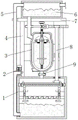
图1为本发明的主视剖视图;Fig. 1 is the front sectional view of the present invention;
图2为本发明的主视图;Fig. 2 is the front view of the present invention;
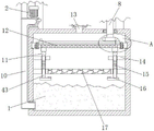
图3为本发明的过滤仓的主视剖视放大图;Fig. 3 is the front sectional enlarged view of the filter chamber of the present invention;
图4为本发明的加热保护炉的主视剖视放大图;Fig. 4 is the front sectional enlarged view of the heating protection furnace of the present invention;
图5为本发明的转动杆的主视剖视放大图;Fig. 5 is the front sectional enlarged view of the rotating lever of the present invention;
图6为本发明的过滤网板的立体结构示意图;Fig. 6 is the three-dimensional structure schematic diagram of the filter screen plate of the present invention;
图7为本发明的齿条的俯视剖视图;7 is a top sectional view of the rack of the present invention;
图8为本发明的U型转动杆的主视剖视放大图;Fig. 8 is the front sectional enlarged view of the U-shaped rotating rod of the present invention;
图9为本发明的图3的A处结构放大示意图;FIG. 9 is an enlarged schematic view of the structure at A of FIG. 3 of the present invention;
图10为本发明的图5的B处结构放大示意图。FIG. 10 is an enlarged schematic view of the structure at B in FIG. 5 of the present invention.
图中:1、过滤仓;2、水泵;3、加热保温炉;4、支撑杆;5、排水管;6、清水仓;7、安装板;8、第一转动杆;9、第一密封板;10、进水管;11、撞击球;12、过滤网板;13、连接管;14、安装杆;15、第一弹簧;16、撞击块;17、活性炭过滤网板;18、伞齿轮;19、伞齿圈;20、环形滑槽;21、环形滑杆;22、第一梯形块;23、提示灯;24、齿条;25、齿轮;26、第二转动杆;27、进水管;28、密封槽;29、伺服电机;30、第二梯形块;31、U型转动杆;32、铰接杆;33、第二密封板;34、第二弹簧;35、第一连接杆;36、浮漂;37、套圈;38、重物块;39、按压板;40、通槽;41、金属接触块;42、清洁刮板;43、第二连接杆;44、滑槽;45、L型固定板;46、第三弹簧。In the figure: 1. Filter bin; 2. Water pump; 3. Heating and holding furnace; 4. Support rod; 5. Drain pipe; 6. Clean water bin; 7. Mounting plate; 8. First rotating rod; plate; 10, water inlet pipe; 11, impact ball; 12, filter screen plate; 13, connecting pipe; 14, installation rod; 15, first spring; 16, impact block; 17, activated carbon filter screen plate; 18, bevel gear ; 19, bevel gear ring; 20, annular chute; 21, annular sliding rod; 22, the first trapezoidal block; 23, prompt light; 24, rack; 25, gear; 26, the second rotating rod; 27, advance Water pipe; 28, sealing groove; 29, servo motor; 30, second trapezoidal block; 31, U-shaped rotating rod; 32, hinge rod; 33, second sealing plate; 34, second spring; 35, first connecting rod ;36, floating; 37, ferrule; 38, heavy block; 39, pressing plate; 40, through groove; 41, metal contact block; 42, cleaning scraper; 43, second connecting rod; 44, chute; 45. L-shaped fixing plate; 46. The third spring.
具体实施方式Detailed ways
下面将结合本发明实施例中的附图,对本发明实施例中的技术方案进行清楚、完整地描述,显然,所描述的实施例仅仅是本发明一部分实施例,而不是全部的实施例。基于本发明中的实施例,本领域普通技术人员在没有做出创造性劳动前提下所获得的所有其他实施例,都属于本发明保护的范围。The technical solutions in the embodiments of the present invention will be clearly and completely described below with reference to the accompanying drawings in the embodiments of the present invention. Obviously, the described embodiments are only a part of the embodiments of the present invention, but not all of the embodiments. Based on the embodiments of the present invention, all other embodiments obtained by those of ordinary skill in the art without creative efforts shall fall within the protection scope of the present invention.
请参阅图1-10,本发明提供一种技术方案:一种用于酒店的节能设备及使用方法,包括过滤仓1,过滤仓1内部的中间位置处设有活性炭过滤网板17,过滤仓1内侧的顶部设有环形滑槽20,环形滑槽20的内部滑动设有环形滑杆21,环形滑杆21的底部设有过滤网板12,过滤网板12底部的边缘处均匀设有第一梯形块22,环形滑杆21的顶部设有伞齿圈19,过滤仓1内部两侧靠近活性炭过滤网板17的正上方设有撞击组件,便于提高过滤网板12和活性炭过滤网板17的过滤效率以延长其使用寿命,过滤仓1顶部的四角处皆设有支撑杆4,四组支撑杆4的顶部共同设有安装板7,安装板7的顶部设有清水仓6,过滤仓1顶部一侧的中间位置处设有水泵2,水泵2的输入端设有延伸至过滤仓1内底部一侧的进水管10;1-10, the present invention provides a technical solution: an energy-saving equipment for hotels and a method of use, comprising a
水泵2的输出端设有延伸至清水仓6内顶部一侧的排水管5,四组支撑杆4相靠近的一侧共同设有加热保温炉3,加热保温炉3的底部设有与过滤仓1内部相连通的连接管13,连接管13的内部设有延伸至其外部的第一密封板9,加热保温炉3一侧的顶部设有与清水仓6内底部一侧相连通的进水管27,进水管27的外侧设有密封槽28,加热保温炉3顶部的中间位置处设有延伸至其内部的第二转动杆26,第二转动杆26的两侧设有与加热保温炉3内侧相贴合的清洁刮板42,第二转动杆26的内部设有警示组件,便于实现自动清洁工作无需操作人员在进行繁琐的手动清洁工作提高该设备使用的便捷性,安装板7底部的中间位置处设有驱动组件,便于驱动清洁刮板42进行转动以便对加热保温炉3的内部进行冲洗刮式工作,以便提高清洁效率,同端两组支撑杆4正面一端的顶部皆设有提示灯23。The output end of the
作为本实施例的优选方案:撞击组件包括安装杆14、第一弹簧15、撞击块16、撞击球11和第二连接杆43,安装杆14设有两组,两组安装杆14位于过滤仓1内部两侧靠近活性炭过滤网板17的正上方,两组安装杆14的内部皆贯穿设有第二连接杆43并延伸至活性炭过滤网板17的外部,两组第二连接杆43的顶部皆设有与第一梯形块22相配合的撞击球11,两组第二连接杆43的外侧皆套设有与安装杆14和活性炭过滤网板17相连接的第一弹簧15,两组第二连接杆43的底部皆设有与活性炭过滤网板17相配合的撞击块16,便于提高过滤网板12和活性炭过滤网板17的过滤效率以延长其使用寿命。As a preferred solution of this embodiment: the impact assembly includes a mounting
作为本实施例的优选方案:警示组件包括第二弹簧34、第一连接杆35、浮漂36、套圈37、重物块38、按压板39、通槽40和金属接触块41,第二弹簧34位于第二转动杆26的内底部,第二弹簧34的顶部设有第一连接杆35,第一连接杆35的顶部和第二转动杆26的内顶部皆设有金属接触块41,且两组金属接触块41相互配合,通槽40设有两组,两组通槽40位于第二转动杆26的两侧,两组通槽40的内部皆滑动设有按压板39,且按压板39与第一连接杆35两侧的底部相连接,套圈37套设与第二转动杆26的外侧,套圈37的外侧设有浮漂36,套圈37底部的两侧皆设有重物块38,便于实现自动清洁工作无需操作人员在进行繁琐的手动清洁工作提高该设备使用的便捷性。As a preferred solution of this embodiment: the warning assembly includes a
作为本实施例的优选方案:驱动组件包括伺服电机29、第二梯形块30、U型转动杆31、铰接杆32、第二密封板33、滑槽44、L型固定板45、第三弹簧46、齿条24、齿轮25、第一转动杆8和伞齿轮18,伺服电机29位于安装板7底部的中间位置处,伺服电机29的输出端设有U型转动杆31,且U型转动杆31的底部并与第二转动杆26相互连接,U型转动杆31的外侧套设有铰接杆32,铰接杆32远离U型转动杆31的一侧套设有延伸至密封槽28内部并与其相配合的第二密封板33,L型固定板45位于安装板7底部远离排水管5一侧的中间位置处;As a preferred solution of this embodiment: the drive assembly includes a
L型固定板45的正面一端设有齿条24,齿条24的背面一端设有与L型固定板45相配合的滑槽44,齿条24的一侧设有与U型转动杆31相配合的第二梯形块30,滑槽44内部靠近第二梯形块30的一侧设有与L型固定板45相连接的第三弹簧46,第一转动杆8位于过滤仓1顶部远离水泵2一侧的中间位置处,第一转动杆8的顶部和底部分别设有与齿条24和伞齿圈19相啮合的齿轮25和伞齿轮18,便于驱动清洁刮板42进行转动以便对加热保温炉3的内部进行冲洗刮式工作,以便提高清洁效率。The front end of the L-shaped
作为本实施例的优选方案:同侧两组支撑杆4相靠近的一侧皆设有固定板,且固定板套设在第一转动杆8的外侧,便于固定安装第一转动杆8。As a preferred solution of this embodiment, the two groups of
作为本实施例的优选方案:加热保温炉3底部的一侧和正面一端顶部的一侧分别设有出水连接管和进水连接口,加热保温炉3的正面一端设有液态观察窗,便于对加热保温炉3的内部进行灌输水源和取出水源使用。As the preferred solution of this embodiment: one side of the bottom of the heating and holding
作为本实施例的优选方案:第二转动杆26内部两侧的顶部均匀设有与其外部相连通的通孔,第二转动杆26内侧的顶部设有与第一连接杆35相配合的密封圈,便于对第二转动杆26的内顶部进行密封工作,防止加热保温炉3内部热水高温进入至其内部对金属接触片41的工作产生影响。As a preferred solution of this embodiment: the tops of both inner sides of the second
作为本实施例的优选方案:过滤网板12内部的两侧皆套设有固定螺栓,环形滑杆21内部的两侧皆设有固定螺孔,且固定螺孔与固定螺栓相互配合,便于固定安装过滤网板12。As a preferred solution of this embodiment: both sides of the
作为本实施例的优选方案:多组第一梯形块22的一侧和第二梯形块30的一侧皆设有倾斜面,且倾斜面与撞击球11和U型转动杆31相互配合,便于第一梯形块22转动时推动撞击球进行移动,便于U型转动杆31转动时可推动第二梯形块30进行移动。As a preferred solution of this embodiment: one side of the first
一种用于酒店的节能设备及使用方法的使用方法,使用步骤如下:A method of using energy-saving equipment for hotels and a method of using the same, the use steps are as follows:
步骤一:首先,可对清水仓6和加热保温炉3的内部加入适量冷水,然后通过加热保温炉3的工作可对其内部冷水进行加热工作,为酒店内部提供热水,当加热保温炉3内部热水逐渐减少时,可使两组金属接触块41相互远离打开提示灯23对操作人员进行提示工作,便于告知操作人员加热保温炉3内部热水使用完成,此时通过伺服电机29可带动U型转动杆31和第二转动杆26与清洁刮板42同时进行转动,便于对加热保温炉3的内侧进行清洁工作,同时U型转动杆31的转动可使得清水仓6内部冷水进入至加热保温炉3的内部进行冲洗,冲洗完成后的污水可通过第一密封板9的打开,通过连接管13流入至过滤仓1的内部;Step 1: First, an appropriate amount of cold water can be added to the interior of the
步骤二:通过过滤仓1内部设计的过滤网板12和活性炭过滤网板17可对污水进行过滤工作,过滤完成后的污水可存储至过滤仓1的内底部,然后通过水泵2的工作可将过滤仓1过滤完成后的清水抽入至清水仓6的内部,已实现清水仓6内部冷水的循环使用,降低水源浪费,提高该设备使用的节能性;Step 2: The sewage can be filtered through the
步骤三:通过U型转动杆31的转动可推动齿条24移动,使得齿条24在移动过程中带动齿轮25、第一转动杆8、伞齿轮18和伞齿圈19同时进行转动,通过环形滑杆21可第一梯形块22进行转动,使得可推动撞击球11和撞击块16远离与过滤网板12和活性炭过滤网板17的贴合,最后再通过第一弹簧15的弹性恢复力带动撞击球11和撞击块16复原对过滤网板12和活性炭过滤网板17进行撞击工作,以提高过滤网板12和活性炭过滤网板17的过滤效率,防止其发生堵塞现象;Step 3: Through the rotation of the U-shaped
步骤四:当清洁工作完成后,停止水泵2的抽水工作,然后操作人员通过第一密封板9对连接管13进行密封工作,然后再对加热保温炉3的内部进行灌输冷水,当冷水水位上升时,可带动两组金属接触块41接触,从而关闭伺服电机29及其以上部件的工作,以便通过加热保温炉3再次对冷水进行加热工作;Step 4: When the cleaning work is completed, stop the pumping work of the
实施例1:如图1、2、3和4所示,当冲洗完抽的污水可通过连接管13流入至过滤仓1的内部时,通过过滤仓1内部设计的过滤网板12和活性炭过滤网板17可对污水进行过滤工作,过滤完成后的污水可存储至过滤仓1的内底部,然后通过水泵2的工作可将过滤仓1过滤完成后的清水抽入至进水管10的内部,再通过进水管10传输至排水管5的内部,最后再通过排水管5排入至清水仓6的内部,已实现清水仓6内部冷水的循环使用,降低水源浪费,提高该设备使用的节能性。Example 1: As shown in Figures 1, 2, 3 and 4, when the flushed and pumped sewage can flow into the interior of the
实施例2:如图1、4、5和10所示,当清洁工作完成后,停止水泵2的抽水工作,然后操作人员通过第一密封板9对连接管13进行密封工作,然后再对加热保温炉3的内部进行灌输冷水,当冷水水位上升时,可带动浮漂36漂浮,使得套圈37带动重物块38在第二转动杆26的外侧滑动上移,从而可使得重物块38脱离与按压板39的放置,解除对第二弹簧34的压缩工作,然后通过第二弹簧34的弹性恢复力可带动第一连接杆35复位,使得第一连接杆35带动一组金属接触块41与另一组金属接触块41相互接触,进而可关闭伺服电机29的转动工作,当加热保温炉3内部冷水灌输完成后,可再次通过加热保温炉3对冷水进行加热工作。Example 2: As shown in Figures 1, 4, 5 and 10, when the cleaning work is completed, the pumping work of the
工作原理:首先,可对清水仓6和加热保温炉3的内部加入适量冷水,然后通过加热保温炉3的工作可对其内部冷水进行加热工作,以便为酒店内部提供热水,当加热保温炉3内部热水逐渐减少时,通过重物块38的重量可带动套圈37和浮漂36同时在第二转动杆26的外部进行滑动下移,当下移至指定位置处时,可使得套圈37及其以上部件置于按压板39的顶部,然后在通过重物块38的自重带动第一连接杆35在第二转动杆26的内部下移对第二弹簧34进行压缩工作,从而可使第一连接杆35带动一组金属接触块41与另一组金属接触块41相互远离工作,通过两组金属接触块41的相互远离可打开提示灯23,通过提示灯23的工作可对操作人员进行提示工作,以便告知操作人员加热保温炉3内部热水使用完成,此时操作人员可拉动第一密封板9解除对连接管13的密封工作;Working principle: First, an appropriate amount of cold water can be added to the interior of the
同时通过两组金属接触块41的相互远离可打开伺服电机29,通过伺服电机29可带动U型转动杆31和第二转动杆26及其以上部件同时进行转动,使得第二转动杆26及其以上部件带动清洁刮板42进行转动,使得清洁刮板42对加热保温炉3的内侧进行清洁工作,同时通过U型转动杆31的转动可带动铰接杆32进行转动移动,使得铰接杆32可对第二密封板33进行拉动工作,从而可使得第二密封板33脱离至密封槽28的内部解除对进水管27的密封,以便清水仓6内部冷水可通过进水管27流入至加热保温炉3的内部进行冲洗工作;At the same time, the
同时通过U型转动杆31的转动可通过第二梯形块30设计的斜面,推动其进行移动,使得第二梯形块30带动齿条24移动,通过齿条24可带动滑槽44在L型固定板45的外侧滑动对第三弹簧46进行压缩工作,同时通过齿条24与齿轮25的相互啮合,使得齿条24在移动过程中带动齿轮25进行转动,通过齿轮25可带动第一转动杆8和伞齿轮18同时进行转动,通过伞齿轮18与伞齿圈19的相互啮合可带动其进行转动,通过伞齿圈19可带动环形滑杆21及其以上部件在环形滑槽20的内部进行转动;At the same time, through the rotation of the U-shaped
可通过环形滑杆21带动过滤网板12和第一梯形块22同时进行转动,通过第一梯形块22转动时的斜面设计,可推动撞击球11带动第二连接杆43在安装杆14的内部进行移动对第一弹簧15进行压缩工作,同时通过第二连接杆43的移动可带动撞击块16脱离与活性炭过滤网板17的贴合,当第一梯形块22转动脱离与撞击球11的推动时,可通过第一弹簧15的弹性恢复力带动撞击球11复原对过滤网板12进行撞击工作,同时还可通过第二连接杆43带动撞击块16复原对活性炭过滤网板17进行撞击工作,从而通过撞击球11与撞击块16的撞击可提高过滤网板12和活性炭过滤网板17的过滤效率,防止其发生堵塞现象。The
最后应当说明的是,以上内容仅用以说明本发明的技术方案,而非对本发明保护范围的限制,本领域的普通技术人员对本发明的技术方案进行的简单修改或者等同替换,均不脱离本发明技术方案的实质和范围。Finally, it should be noted that the above content is only used to illustrate the technical solution of the present invention, rather than limiting the protection scope of the present invention. The essence and scope of the technical solution of the invention.
Claims (10)
Priority Applications (1)
| Application Number | Priority Date | Filing Date | Title |
|---|---|---|---|
| CN202111677005.4A CN115031286A (en) | 2021-12-31 | 2021-12-31 | Energy-saving equipment for hotel and use method |
Applications Claiming Priority (1)
| Application Number | Priority Date | Filing Date | Title |
|---|---|---|---|
| CN202111677005.4A CN115031286A (en) | 2021-12-31 | 2021-12-31 | Energy-saving equipment for hotel and use method |
Publications (1)
| Publication Number | Publication Date |
|---|---|
| CN115031286A true CN115031286A (en) | 2022-09-09 |
Family
ID=83117906
Family Applications (1)
| Application Number | Title | Priority Date | Filing Date |
|---|---|---|---|
| CN202111677005.4A Pending CN115031286A (en) | 2021-12-31 | 2021-12-31 | Energy-saving equipment for hotel and use method |
Country Status (1)
| Country | Link |
|---|---|
| CN (1) | CN115031286A (en) |
Cited By (1)
| Publication number | Priority date | Publication date | Assignee | Title |
|---|---|---|---|---|
| CN115751432A (en) * | 2022-11-07 | 2023-03-07 | 沧州青尚环保科技有限公司 | Indoor heating and ventilation processing system |
Citations (8)
| Publication number | Priority date | Publication date | Assignee | Title |
|---|---|---|---|---|
| US4406794A (en) * | 1979-02-05 | 1983-09-27 | Brigante Miguel F | External sludge collector for boiler bottom blowdown and automatic blowdown control initiated by conductivity probe within the boiler and method |
| JP2001029910A (en) * | 1999-07-27 | 2001-02-06 | Tokyo Electric Power Co Inc:The | Sediment removal device in water tank |
| CN110030734A (en) * | 2019-05-16 | 2019-07-19 | 天津海实翔节能技术有限公司 | A kind of house electric heating heating boiler |
| CN112206562A (en) * | 2020-10-14 | 2021-01-12 | 北京大禹惠民环境科技有限公司 | Dirt blocking structure convenient to clean for water taking pump station and cleaning method of dirt blocking structure |
| CN112283943A (en) * | 2020-10-20 | 2021-01-29 | 广州捷睿科技有限公司 | Surface decontamination device and method for domestic boiler |
| CN112460674A (en) * | 2020-11-29 | 2021-03-09 | 蓝祝生 | Heating device for heating and ventilation engineering |
| CN213192657U (en) * | 2020-06-06 | 2021-05-14 | 宜兴市苏恒环保设备有限公司 | Self-cleaning filter |
| CN213558904U (en) * | 2020-08-05 | 2021-06-29 | 佛山市南海区震利达电器有限公司 | Cleaning device for machining spiral copper pipe |
-
2021
- 2021-12-31 CN CN202111677005.4A patent/CN115031286A/en active Pending
Patent Citations (8)
| Publication number | Priority date | Publication date | Assignee | Title |
|---|---|---|---|---|
| US4406794A (en) * | 1979-02-05 | 1983-09-27 | Brigante Miguel F | External sludge collector for boiler bottom blowdown and automatic blowdown control initiated by conductivity probe within the boiler and method |
| JP2001029910A (en) * | 1999-07-27 | 2001-02-06 | Tokyo Electric Power Co Inc:The | Sediment removal device in water tank |
| CN110030734A (en) * | 2019-05-16 | 2019-07-19 | 天津海实翔节能技术有限公司 | A kind of house electric heating heating boiler |
| CN213192657U (en) * | 2020-06-06 | 2021-05-14 | 宜兴市苏恒环保设备有限公司 | Self-cleaning filter |
| CN213558904U (en) * | 2020-08-05 | 2021-06-29 | 佛山市南海区震利达电器有限公司 | Cleaning device for machining spiral copper pipe |
| CN112206562A (en) * | 2020-10-14 | 2021-01-12 | 北京大禹惠民环境科技有限公司 | Dirt blocking structure convenient to clean for water taking pump station and cleaning method of dirt blocking structure |
| CN112283943A (en) * | 2020-10-20 | 2021-01-29 | 广州捷睿科技有限公司 | Surface decontamination device and method for domestic boiler |
| CN112460674A (en) * | 2020-11-29 | 2021-03-09 | 蓝祝生 | Heating device for heating and ventilation engineering |
Cited By (1)
| Publication number | Priority date | Publication date | Assignee | Title |
|---|---|---|---|---|
| CN115751432A (en) * | 2022-11-07 | 2023-03-07 | 沧州青尚环保科技有限公司 | Indoor heating and ventilation processing system |
Similar Documents
| Publication | Publication Date | Title |
|---|---|---|
| CN110000136A (en) | A kind of cleaning plant of the solar energy photovoltaic panel of environmental protection | |
| CN207277422U (en) | A kind of indoor water treatment facilities | |
| CN115031286A (en) | Energy-saving equipment for hotel and use method | |
| CN211513751U (en) | Filter screen cleaning device for haze air purifier | |
| CN216523359U (en) | Energy-saving scale prevention closed cooling circulation device for thermal power plant | |
| CN211025301U (en) | An oilfield water injection backflushing filter and decontamination device | |
| CN209876887U (en) | Electric boiler with descaling function | |
| CN221825603U (en) | A water tank with a coil fixing structure | |
| CN103290639B (en) | Recovery system for waste heat of printing and dyeing wastewater | |
| CN219481736U (en) | Cleaning mechanism of sewage source heat pump | |
| CN111892266A (en) | A new type of sludge thickening tank | |
| CN118527342A (en) | A screening device for recycling waste NdFeB magnets | |
| CN203256475U (en) | Printing and dyeing wastewater waste heat recovery system | |
| CN211451414U (en) | An environmentally friendly solar water heater with automatic descaling | |
| CN115999238A (en) | Water circulation filtering device and method of geothermal energy system | |
| CN221147320U (en) | A filtration for heat exchanger makes things convenient for dismouting | |
| CN220852622U (en) | Wall-mounted boiler with water filtering function | |
| CN219579981U (en) | A petrochemical filter | |
| CN221063736U (en) | Quartz sand washing machine capable of drying and used for fracturing | |
| CN221548106U (en) | A water conservancy pipeline with dirt interception function | |
| CN218722358U (en) | Descaling device for water heater | |
| CN216726064U (en) | Automatic clean filter | |
| CN217357598U (en) | Integrated pressure-bearing solar vacuum glass heat pipe water heater | |
| CN219103481U (en) | Quick cooler outside tank | |
| CN217781960U (en) | River course floater collection device |
Legal Events
| Date | Code | Title | Description |
|---|---|---|---|
| PB01 | Publication | ||
| PB01 | Publication | ||
| SE01 | Entry into force of request for substantive examination | ||
| SE01 | Entry into force of request for substantive examination | ||
| WD01 | Invention patent application deemed withdrawn after publication | ||
| WD01 | Invention patent application deemed withdrawn after publication |
Application publication date: 20220909 |