Disclosure of Invention
The application provides an electronic equipment, and this electronic equipment can compromise frivolousization design and heat dispersion, is favorable to improving electronic equipment's performance.
The application provides an electronic device, this electronic device includes: the heat dissipation module comprises a shell, a heat dissipation module and a boss, wherein an accommodating space is formed in the shell; the bulge is arranged on the outer surface of the shell, the interior of the bulge is hollow to form a containing groove, the containing groove is communicated with the containing space, and at least part of the heat dissipation module is arranged in the containing groove.
The application provides an electronic equipment, through set up the inside bellying that has the storage tank on the surface of casing to set up the at least part of heat dissipation module in the storage tank, can be with the help of the at least partial heat dissipation module of storage tank holding, under the certain prerequisite of the volume and the thickness of casing, can increase the volume of heat dissipation module, improve heat dispersion of heat dissipation module. Meanwhile, the bulge can support the electronic equipment, the gap between the electronic equipment and the supporting surface is increased, a heat dissipation space is formed between the shell of the electronic equipment and the supporting surface, heat exchange between the electronic equipment and air is facilitated, the dissipation speed of heat inside the electronic equipment can be increased, and the heat dissipation performance of the heat dissipation module can be further improved. Therefore, the electronic equipment provided by the embodiment of the application can give consideration to both light and thin design and heat dissipation performance, and is simple in mechanism and ingenious in design.
In one possible design, the heat dissipation module includes a heat conduction structure and a first heat sink, the heat conduction structure has a first section, the first section is in heat conduction connection with the first heat sink, at least a portion of the first section is located in the receiving groove, and at least a portion of the first heat sink is located in the receiving space. . Therefore, the occupied space of the heat conduction structure and the part in heat conduction connection with the first radiator in the accommodating space can be saved, the size of the first radiator can be further increased, the heat exchange area of the first radiator is increased, and the heat radiation performance of the heat radiation module can be further improved.
In a possible design, the first section is entirely located in the accommodating groove. That is, the whole part of the heat conduction structure in heat conduction connection with the first heat sink is positioned in the accommodating groove. Therefore, the occupied space of the part of the heat conduction structure in heat conduction connection with the first radiator in the accommodating space can be further saved, the size of the first radiator can be further increased, the heat exchange area of the first radiator is increased, and the heat radiation performance of the heat radiation module can be further improved.
In a possible design, a portion of the first segment is located in the receiving groove. One part of the heat conduction structure in heat conduction connection with the first radiator is arranged in the accommodating groove. Therefore, the occupied space of the heat conduction structure and the part in heat conduction connection with the first radiator in the accommodating space can be saved, the size of the first radiator can be further increased, the heat exchange area of the first radiator is increased, and the heat radiation performance of the heat radiation module can be further improved.
In one possible design, a side surface of the first section facing the accommodating space is flush with the notch of the accommodating groove, or a side surface of the first section facing the accommodating space is lower than the notch of the accommodating groove.
In one possible embodiment, a side surface of the first section facing away from the receiving space adjoins the inner bottom wall and/or the inner side wall of the receiving groove. Therefore, the first section can be sunk into the accommodating groove to the maximum extent, so that the volume of the first radiator can be further increased, and the radiating efficiency is improved.
In a possible design, a side surface of the first section facing away from the accommodating space is spaced from an inner bottom wall of the accommodating groove, the heat dissipation module further includes a second heat sink connected to the first section in a heat-conducting manner, and the second heat sink and the first heat sink are respectively located at two opposite sides of the first section. Therefore, the space in the accommodating groove can be fully utilized, the volume of the radiator is further increased on the basis of not increasing the whole thickness of the electronic equipment, and the radiating efficiency is further improved.
In a possible design manner, the second heat sink is in contact with the inner bottom wall of the accommodating groove, or the second heat sink is in contact with the inner side wall of the accommodating groove, or the second heat sink is in contact with both the inner bottom wall and the inner side wall of the accommodating groove.
In one possible embodiment, the first heat sink and the second heat sink are formed as a single-piece structure. Therefore, the structure of the heat dissipation module can be simplified, and the production efficiency and the assembly efficiency are improved.
In a possible design manner, the protrusion portion is provided with a first heat dissipation hole communicating the accommodating groove and the outside of the protrusion portion. Therefore, the heat on the first radiator or the second radiator positioned in the accommodating groove can be discharged to the outside of the electronic equipment through the first heat dissipation hole, and the heat dissipation efficiency is further improved.
In one possible embodiment, the first heat sink is located entirely within the receiving space. Like this, can avoid the inside wall of storage tank to block the circulation of heat transfer air current, and then can improve the heat dispersion of first radiator. On the basis, the part of the heat conduction structure in heat conduction connection with the first radiator can be integrally arranged in the accommodating groove. Therefore, circulation of air exchanging heat with the first radiator in the accommodating space can be guaranteed, the size of the first radiator can be increased, and the heat radiation performance of the heat radiation module is further improved.
In a possible design mode, the housing is provided with a second heat dissipation hole for communicating the accommodating space with the outside of the housing. In this way, the heat on the first heat sink can be discharged out of the electronic device through the second heat dissipation hole.
In one possible design, the housing is provided with an air inlet which communicates the accommodating space with the outside of the housing. Therefore, after external air flow enters the accommodating space from the air inlet, the external air flow exchanges heat with the first radiator, and the air flow after heat exchange is discharged to the outside of the electronic equipment through the second heat dissipation hole. Therefore, the air flow mobility of the accommodating space can be improved, and the heat dissipation performance of the heat dissipation module is further improved.
In a possible design, the heat dissipation module further includes a fan disposed in the accommodating space, the fan has a fan inlet and a fan outlet, the fan inlet is communicated with the air inlet, the fan outlet is communicated with the second heat dissipation hole, and the first heat sink is disposed between the fan outlet and the second heat dissipation hole. The fan is used for driving airflow to flow to the second heat dissipation hole from the air inlet. Therefore, under the driving of the fan, the airflow enters the accommodating space from the air inlet and flows to the fan outlet through the fan inlet of the fan, and the airflow blown out from the fan outlet exchanges heat with the first radiator and then flows to the second heat dissipation hole and is discharged out of the electronic equipment through the second heat dissipation hole. Therefore, by arranging the fan, the airflow flowing speed in the accommodating space can be improved, and the heat dissipation performance of the heat dissipation module is further improved.
In one possible embodiment, the heat conducting structure comprises: the heat conducting fins are connected with the heating element in the shell in a heat conduction way; the soaking piece includes evaporation zone and condensation segment, and evaporation zone and condensation segment are located soaking piece extending direction's both ends respectively, and the condensation segment forms first district section, and the condensation segment is connected with first radiator heat-conduction, and the evaporation zone is connected with the conducting strip. Simple structure and convenient processing.
In a possible design, the free end of the condensation section is provided with a flange, which is in heat-conducting connection with the first heat sink. Thus, the contact area between the first heat sink and the soaking member can be increased, and the heat conduction efficiency between the first heat sink and the soaking member can be increased.
In a possible design mode, the heat conducting fins and the soaking pieces are soaking plates, and the heat conducting fins and the soaking pieces are of an integrated structure. That is, the heat conducting fin and the soaking member are integrally formed.
In one possible embodiment, the evaporation section and the condensation section are bent to form a section difference, so that the evaporation section and the condensation section are located at different heights. Like this, when the assembly, can set up the condensation segment of soaking piece in the storage tank, the assembly of the soaking piece of being convenient for can guarantee the heat-conduction between evaporation zone and the heating element simultaneously and be connected, has reduced the assembly degree of difficulty, is favorable to improving assembly efficiency.
In one possible embodiment, the stepped section is in thermally conductive connection with the first heat sink. Thus, the contact area between the first heat sink and the soaking member can be increased, and the heat conduction efficiency between the first heat sink and the soaking member can be increased.
In one possible design, the heat pipe includes a pipe shell, a wick, and an end cap, the pipe shell is formed in a hollow structure, the wick covers an inner wall of the pipe shell, the pipe shell is filled with a working liquid, and the end cap is used for sealing the pipe shell.
In one possible embodiment, the heat pipe is formed as a flat pipe.
In one possible design, the heat generating element includes at least one of a CPU and a GPU.
In one possible design, the first heat sink includes: the heat dissipation substrate is connected with the heat conduction structure; every radiating fin all fixes on the radiating base plate, and a plurality of radiating fins set up at interval on the radiating base plate. A heat dissipation channel is defined between two adjacent heat dissipation fins, and when air flows through the heat dissipation channel, the air can exchange heat with the heat dissipation fins, so that heat on the heat dissipation fins can be brought to the outside of the electronic equipment through the air.
In one possible embodiment, each heat sink fin is arranged perpendicular to the heat sink base. Therefore, the structure of the first radiator is more compact, the heat dissipation area of the first radiator is increased, and the heat dissipation performance of the heat dissipation module can be improved, so that the performance of the electronic equipment is improved.
In one possible design, the air inlet and the projection are formed on the same side surface of the housing.
In one possible embodiment, the surface of the projection facing away from the housing is formed as a plane. That is, the end surface of the free end of the boss is formed as a flat surface. Thus, the contact area between the protruding part and the supporting surface can be increased, and the supporting stability of the protruding part is improved.
In one possible embodiment, the surface of the projection remote from the housing is provided with an anti-slip structure. Therefore, the anti-skid performance and the wear resistance of the protruding portion can be improved, and the supporting stability and the reliability of the protruding portion are improved.
In one possible embodiment, the anti-slip structure is a non-slip mat arranged on the raised portion.
In one possible design, the anti-slip structure is a stud formed on the surface of the boss.
In a possible design, the anti-slip structure may also be an anti-slip groove formed on the surface of the protrusion.
In one possible embodiment, the projection is of one-piece construction with the housing. That is, the boss is integrally formed with the housing. Illustratively, the boss is injection molded integrally with the housing. Therefore, the processing technology of the shell can be simplified, the assembling step of the shell can be omitted, meanwhile, the connection strength between the protruding part and the shell can be improved, and the connection reliability between the protruding part and the shell is improved.
In a possible embodiment, the housing comprises a first wall, the projection is provided on an outer surface of the first wall, and a projection direction of the projection is perpendicular to the first wall or inclined with respect to the first wall. The first wall may be a bottom panel of the housing. Therefore, at least part of the heat dissipation module is conveniently arranged in the accommodating groove, and the electronic equipment can be stably supported through the protruding part. In addition, the processing difficulty of the shell can be simplified, and the processing efficiency is improved.
In one possible design, the electronic device is a notebook computer, the notebook computer includes a keyboard host, and the protrusion is disposed on a bottom surface of the keyboard host. When placing electronic equipment on the holding surface (for example desktop etc.), electronic equipment can utilize this bellying and holding surface contact, and like this, electronic equipment sets up the relative other end of one end of bellying and raises, has increased the clearance between electronic equipment and the holding surface, forms heat dissipation space between messenger electronic equipment's casing and the holding surface, and the electronic equipment of being convenient for carries out the heat transfer with the air, can increase the inside thermal speed of giving off of electronic equipment, and then can further improve heat dissipation module's heat dispersion.
In one possible design, the projection is disposed near the rear end of the keyboard host. Therefore, the comfort of the user using the electronic equipment can be improved, and the fatigue can be relieved.
In one possible design, the notebook computer further includes: the supporting legs are arranged on the bottom surface of the keyboard host, and the supporting legs are arranged close to the front end of the keyboard host. Thus, the gap between the electronic equipment and the supporting surface can be further increased, and the heat dissipation space of the electronic equipment is enlarged, so that the heat dissipation efficiency is improved.
In one possible design, the height of the supporting legs protruding from the bottom surface of the main body is less than or equal to the height of the protruding portion protruding from the bottom surface of the main body. Therefore, the supporting legs are protruded out of the bottom surface of the keyboard host, the height of the supporting legs protruding out of the bottom surface of the keyboard host is smaller than or equal to the height of the protruding portions protruding out of the bottom surface of the keyboard host, so that the comfort of a user using the electronic equipment can be improved, and the supporting legs are favorable for relieving fatigue.
In one possible design, the electronic device is a tablet computer, and the protruding portion is disposed on a back cover of the tablet computer.
Detailed Description
In the embodiments of the present application, the terms "first", "second", "third", and "fourth" are used for descriptive purposes only and are not to be construed as indicating or implying relative importance or implying any number of technical features indicated. Thus, features defined as "first", "second", "third", "fourth" may explicitly or implicitly include one or more of the features.
In the embodiments of the present application, the terms "include", "include" or any other variations are intended to cover non-exclusive inclusions, so that a process, a method, an article, or an apparatus including a series of elements includes not only those elements but also other elements not explicitly listed, or further includes elements inherent to such a process, a method, an article, or an apparatus. Without further limitation, an element defined by the phrase "comprising an … …" does not exclude the presence of other like elements in a process, method, article, or apparatus that comprises the element.
In the embodiment of the present application, "and/or" is only one kind of association relationship describing an association object, and indicates that three relationships may exist, for example, a and/or B may indicate: a exists alone, A and B exist simultaneously, and B exists alone. In addition, the character "/" herein generally indicates that the former and latter related objects are in an "or" relationship.
The present application provides an electronic device 100, wherein the electronic device 100 is a type of electronic device 100 having a heat dissipation module 25. Specifically, the electronic device 100 includes, but is not limited to, a mobile phone, a tablet computer (tab let personal computer), a laptop computer (laptop computer), a Personal Digital Assistant (PDA), a personal computer, a notebook computer (notebook), a vehicle-mounted device, and a wearable device, etc. the electronic device 100 may be a mobile phone, a tablet computer (tablet let personal computer), a laptop computer (laptop), a PDA, or a mobile phone.
Referring to fig. 1, fig. 1 is a schematic structural diagram of an electronic device 100 according to some embodiments of the present disclosure. In this embodiment, the electronic device 100 is a notebook computer. Specifically, the electronic device 100 includes a display 1 and a keyboard host 2.
The display 1 is used to display images, videos, and the like. The keyboard main body 2 is rotatably connected with the display 1. The keyboard host 2 is used for inputting instructions and data and controlling the display 1 to display images and videos according to the input instructions and data. Meanwhile, the keyboard main body 2 is also used for playing voice or music.
The electronic device 100 is capable of switching between an open state and a closed state. When the electronic device 100 is in the open state, the display 1 and the keyboard host 2 form an included angle greater than 0 ° and less than 180 °. When the electronic device 100 is in the closed state, the display 1 covers the keyboard host 2, and the display surface of the display 1 is opposite to the keyboard 23 surface of the keyboard host 2.
For convenience of the following description of the embodiments, an XYZ coordinate system is established for the keyboard host 2. Specifically, the extending direction of the rotation axis of the keyboard main body 2 and the display 1 is defined as an X-axis direction, the thickness direction of the keyboard main body 2 is defined as a Z-axis direction, and the direction perpendicular to both the X-axis direction and the Z-axis direction is defined as a Y-axis direction. It is understood that the coordinate system of the keyboard host 2 can be flexibly configured according to actual needs, and is not limited in particular.
Referring to fig. 2, fig. 2 is a perspective view of the keyboard main body 2 of the electronic device 100 shown in fig. 1, and fig. 3 is a cross-sectional view taken along the line a-a of the perspective view shown in fig. 2. It should be noted that "at line a-a" means at the plane where the arrows at the two ends of line a-a and line a-a are located, and the description of the similar drawings shall be understood in the following, and will not be repeated herein. In the present embodiment, the keyboard host 2 includes a housing 21, a middle plate 22, a keyboard 23, a main board 24 and a heat dissipation module 25.
It should be noted that fig. 2 to fig. 3 only schematically show some components included in the keyboard main body 2, and the actual shape, the actual size, the actual position, and the actual configuration of these components are not limited by fig. 2 and fig. 3 and the following drawings.
The housing 21 serves to protect the internal structure of the keyboard main unit 2. The housing 21 may be a unitary structure or may be formed by assembling a plurality of parts. In some embodiments, referring to fig. 2-3, the housing 21 includes a C-shell 211 and a D-shell 212. The C-shell 211 is mated with the D-shell 212 to enclose the inner accommodating space 21a of the housing 21. The C shell 211 and the D shell 212 may be fixed by clamping, or may be fixed by gluing, or may be fixed by screwing, and is not limited specifically herein.
The middle plate 22 is located in the inner receiving space 21a of the housing 21. The middle plate 22 is fixed on the inner surface of the C-shell 211 by gluing, clamping, screwing, riveting, etc. In other embodiments, the middle plate 22 may also be fixed to the inner surface of the D-shell 212. The material of the middle plate 22 includes, but is not limited to, plastic and metal. Midplane 22 serves as a support "skeleton" for the electronic components within keyboard host 2. The keyboard 23 and the heat sink module 25 are fixed to the middle plate 22 by direct or indirect means.
The keyboard 23 is used for inputting instructions and data. The keypad 23 includes a fixing plate 231 and a plurality of keys 232 connected to the fixing plate 231. Referring to fig. 3, the fixing plate 231 is fixed on the middle plate 22. The middle plate 22 is provided with a first avoidance port 22 a. A second avoiding opening 211a is formed in the position, corresponding to each key 232, of the C shell 211. The key 232 passes through the first avoiding opening 22a and the second avoiding opening 211a corresponding to the key 232 and extends out of the C-shell 211.
The main board 24 is used for integrating a control chip. The control chip may include a Central Processing Unit (CPU), a Graphics Processing Unit (GPU), an application processing unit (AP), a double data rate synchronous dynamic random access memory (DDR), a universal memory (UFS), and the like.
The main board 24 may be a hard circuit board, a flexible circuit board, or a rigid-flexible circuit board. The main board 24 may be an FR-4 dielectric board, a Rogers (Rogers) dielectric board, a hybrid FR-4 and Rogers dielectric board, or the like. Here, FR-4 is a code for a grade of flame-resistant material, and the Rogers dielectric plate is a high-frequency plate.
The heat dissipation module 25 is disposed in the accommodating space 21a, and the heat dissipation module 25 is used for dissipating heat of the heating element 3 in the electronic device 100 to ensure normal operation of the electronic device 100. For example, the heat generating element 3 may include at least one of a CPU and a GPU on the motherboard 24. That is, the heat dissipation module 25 may be used to cool at least one of the CPU and the GPU on the motherboard 24. Referring to fig. 3, the heat dissipation module 25 is fixed on the motherboard 24 and is connected to the CPU and the GPU in a heat conduction manner.
As the transistor density of various chips (particularly CPUs) in the electronic device 100 increases, the electronic device 100 has an increasing demand for heat dissipation. In order to increase the heat dissipation performance of the heat dissipation module 25, the volume of the heat dissipation module 25 has to be increased. This increases the thickness of the electronic device 100, which is disadvantageous for achieving a slim design of the electronic device 100.
To solve the contradiction between the light and thin design and the heat dissipation performance of the electronic device 100, please refer to fig. 4, and fig. 4 is a cross-sectional view of the keyboard host 2 according to another embodiment of the present application. The electronic device 100 in the present embodiment is different from the keyboard host 2 of the electronic device 100 shown in fig. 2 in that: the keyboard host 2 in this embodiment includes a protruding portion 213, in addition to the housing 21, the middle plate 22, the keyboard 23, the main board 24 and the heat sink module 25 of the keyboard host 2 shown in fig. 2, the protruding portion 213 is disposed on the bottom surface of the housing 21 and protrudes from the bottom surface of the housing 21. The protrusion 213 is hollow to form a receiving groove 213a, the receiving groove 213a is communicated with the receiving space 21a, and at least a portion of the heat dissipation module 25 is disposed in the receiving groove 213 a. That is, a portion of the heat dissipation module 25 is disposed in the receiving groove 213a, or the heat dissipation module 25 is disposed in the receiving groove 213 a. Thus, at least a portion of the heat dissipation module 25 can be accommodated in the accommodation groove 213a, and the volume and thickness of the housing 21 can be constant, so as to increase the volume of the heat dissipation module 25 and improve the heat dissipation performance of the heat dissipation module 25.
Meanwhile, when the electronic device 100 is placed on a supporting surface (for example, a desktop, etc.), the electronic device 100 may contact the supporting surface by using the protruding portion 213, so that one end of the electronic device 100, which is provided with the protruding portion 213, is raised relative to the other end, thereby increasing a gap between the electronic device 100 and the supporting surface, forming a heat dissipation space between the housing 21 of the electronic device 100 and the supporting surface, facilitating heat exchange between the electronic device 100 and air, increasing the heat dissipation speed of the inside of the electronic device 100, and further improving the heat dissipation performance of the heat dissipation module 25.
It should be noted that fig. 4 only shows an example that the protruding portion 213 is disposed on the bottom surface of the casing 21, and when the electronic device 100 has other structures, such as a display of a notebook computer, a tablet computer, and a mobile phone, the protruding portion 213 may be disposed on the back surface, the side surface, and the like of the casing 21. For example, when the electronic device 100 is a router, the protrusion 213 may be disposed on any side surface of the housing 21. The specific position of the protrusion 213 is not limited in the present application, as long as the protrusion 213 is located on the outer surface of the housing 21 and protrudes toward the outside of the housing 21, so as to expand more space inside the protrusion 21 to accommodate the heat dissipation module 25.
In the electronic device 100 provided in the embodiment of the present application, the protrusion 213 having the receiving groove 213a therein is disposed on the outer surface of the housing 21, and at least a portion of the heat dissipation module 25 is disposed in the receiving groove 213a, so that at least a portion of the heat dissipation module 25 can be received by the receiving groove 213a, and on the premise that the size and the thickness of the housing 21 are fixed, the size of the heat dissipation module 25 can be increased, and the heat dissipation performance of the heat dissipation module 25 can be improved. Meanwhile, the protruding portion 213 can support the electronic device 100, reduce the contact area between the electronic device 100 and the supporting surface, increase the radiating speed of the heat inside the electronic device 100, and further improve the heat dissipation performance of the heat dissipation module 25. Therefore, the electronic device 100 provided by the embodiment of the application can give consideration to both the light and thin design and the heat dissipation performance, and is simple in mechanism and ingenious in design.
In some embodiments, the boss 213 is a unitary structure with the housing 21. That is, the boss 213 is integrally formed with the housing 21. Illustratively, the boss 213 is injection molded integrally with the housing 21. Thus, the process of manufacturing the housing 21 can be simplified, the assembly step of the housing 21 can be omitted, the connection strength between the protruding portion 213 and the housing 21 can be improved, and the connection reliability between the protruding portion 213 and the housing 21 can be improved.
In other embodiments, the protrusion 213 and the housing 21 may be a separate structure. That is, after the protruding portion 213 and the housing 21 are separately formed, the protruding portion 213 is fixed to the housing 21 by bonding, snapping, screwing, or the like.
In some embodiments, referring to fig. 4, the protrusion 213 is disposed near the rear end of the keyboard host 2. In this way, the comfort of the user using the electronic apparatus 100 can be improved, which is advantageous for relieving fatigue.
Specifically, the housing 21 includes a first wall plate, and the boss is provided on an outer surface of the first wall plate. It will be appreciated that the first wall is the wall of the housing 21 provided with the boss 213. In the example of fig. 4, the first wall plate is a bottom plate of the housing 21. In other embodiments, the first wall plate may be a back plate, a side plate, or the like of the housing 21.
In some embodiments, referring to fig. 4, the protrusion direction of the protrusion 213 is perpendicular to the first wall of the housing 21. That is, the central axis O of the boss 213 is perpendicular to the first wall plate of the housing 21. Therefore, at least a portion of the heat dissipation module 25 is conveniently disposed in the receiving groove 213a, and the electronic device 100 can be stably supported by the protrusion 213. In addition, the difficulty of processing the housing 21 can be simplified, and the processing efficiency can be improved.
In other embodiments, the protruding direction of the protruding portion 213 may also be inclined with respect to the first wall of the housing 21, and the central axis O of the protruding portion 213 is inclined with respect to the first wall of the housing 21. For example, referring to fig. 5, fig. 5 is a sectional view of a keyboard host 2 according to some embodiments of the present application. When the protrusion 213 is disposed near the rear end of the housing 21, the protrusion direction of the protrusion 213 may be inclined backward relative to the first wall of the housing 21. Thus, it is also convenient to dispose at least a portion of the heat dissipation module in the receiving groove 213a, and the supporting stability of the protrusion 213 can be improved.
The "back end" described in the present application refers to a direction in which the electronic apparatus 100 is away from the user when the user uses the electronic apparatus 100. Accordingly, the term "front end" as used herein refers to a direction in which the electronic device 100 is close to one end of the user when the user uses the electronic device 100. In addition, in the description of the present application, the terms "front", "back", "bottom", "inside", "outside", and the like indicate orientations or positional relationships based on those shown in the drawings, and are only for convenience of describing the present invention but do not require that the present invention must be constructed and operated in a specific orientation, and thus, should not be construed as limiting the present invention.
It is understood that in other embodiments, when the protrusion 213 is disposed near the front end of the housing 21, the protrusion direction of the protrusion 213 may be inclined forward relative to the first wall of the housing 21 to improve the support stability of the protrusion 213.
Alternatively, the outer side surface of the protrusion 213 may be formed as an arc-shaped surface or a flat surface. This is not particularly limited in this application.
In some embodiments, referring to fig. 4-5, the surface of the protrusion 213 away from the housing 21 is formed as a flat surface. That is, the end surface of the free end of the boss 213 is formed to be flat. Thus, the contact area between the boss 213 and the support surface can be increased, which is advantageous for improving the support stability of the boss 213.
Referring to fig. 6 to 7, fig. 6 is a cross-sectional view of a keyboard host 2 according to still other embodiments of the present application, and fig. 7 is an enlarged view of a portion a in fig. 6. The surface of the boss 213 remote from the housing 21 is provided with a non-slip structure 214. The anti-slip structure 214 in this embodiment is a non-slip pad disposed on the boss 213. Illustratively, the non-slip pad is a rubber pad, a silicone pad, a plastic pad, or the like. The non-slip mat may be secured to the boss 213 by gluing, snapping, screwing, etc. This improves the anti-slip performance and wear resistance of the boss 213, and improves the support stability and reliability of the boss 213.
In other embodiments, please refer to fig. 8-9, fig. 8 is a cross-sectional view of the keyboard host 2 according to still other embodiments of the present application, and fig. 9 is an enlarged view of a portion B in fig. 8. In this embodiment, the anti-slip structure 214 is an anti-slip projection formed on the above-mentioned surface of the projection 213. The anti-slip protrusions protrude from the surface of the protrusion 213. Alternatively, the anti-slip protrusions are formed as a single body with the protrusions 213. This also improves the anti-slip performance and wear resistance of the boss 213, thereby improving the support stability and reliability of the boss 213.
In still other embodiments, please refer to fig. 10-11, fig. 10 is a cross-sectional view of the keyboard main body 2 according to still other embodiments of the present application, and fig. 11 is an enlarged view of a region C in fig. 10. The anti-slip structure 214 may be an anti-slip groove formed on the surface of the protrusion 213. The anti-slip groove is formed by the above surface of the convex portion 213 being concaved toward the direction close to the housing 21. Alternatively, the anti-slip groove and the protrusion 213 are formed in a single body.
Referring to fig. 12, fig. 12 is a bottom view of the keyboard main unit 2 shown in fig. 4. The projection 213 is formed in one and long shape. The extending direction of the projection 213 is parallel to the X-axis direction. In this way, the strip-shaped receiving groove 213a can be formed in the protrusion 213, so that at least a portion of the heat dissipation module 25 can be disposed in the receiving groove 213a, and the heat dissipation module has a simple structure and is easy to process.
On the basis, in order to further increase the gap between the electronic device 100 and the supporting surface, the heat dissipation efficiency is improved. Referring to fig. 13-14, fig. 13 is a cross-sectional view of a keyboard main unit 2 according to still other embodiments of the present application, and fig. 14 is a bottom view of the keyboard main unit 2 shown in fig. 13. The keyboard host 2 in this embodiment is different from the keyboard host 2 shown in fig. 4 in that the keyboard host 2 in this embodiment further includes a supporting leg 26, the supporting leg 26 is disposed on the bottom surface of the casing 21, and the supporting leg 26 is disposed near the front end of the casing 21. That is, the support leg 26 is provided near the front end of the keyboard main unit 2. The supporting feet 26 protrude downward from the bottom surface of the housing 21.
Referring to fig. 13-14, there are two support legs 26, and the two support legs 26 are spaced apart from each other in the X-axis direction. Each of the supporting legs 26 is a strip-shaped structure, and the length direction of the supporting leg 26 is parallel to the X-axis direction. In other embodiments, the supporting foot 26 may be formed as an elongated protrusion extending along the X-axis direction, or the supporting foot 26 may be formed as two hemispherical protrusions spaced apart in the X-axis direction.
In some embodiments, the height of the supporting legs 26 protruding from the bottom surface of the keyboard main body 2 is less than or equal to the height of the protrusions 213 protruding from the bottom surface of the keyboard main body 2. The "height of the protrusion 213 protruding from the bottom surface of the keyboard 23" refers to a distance between one end of the protrusion 213 away from the housing 21 and the housing 21. It can be understood that, when the anti-slip structure 214 is disposed on the protruding portion 213, the distance between the end of the anti-slip structure 214 away from the protruding portion 213 and the casing 21 is the height of the protruding portion 213 protruding from the bottom surface of the keyboard main body 2. Accordingly, the "height of the supporting foot 26 protruding from the bottom surface of the keyboard 23" refers to a distance between one end of the supporting foot 26 away from the casing 21 and the casing 21. Therefore, the height of the supporting legs 26 protruding from the bottom surface of the keyboard main body 2 is less than or equal to the height of the protruding portions 213 protruding from the bottom surface of the keyboard main body 2, so that the comfort of the user using the electronic device 100 can be improved, and the fatigue can be relieved.
Referring to fig. 15-16, fig. 15 is a perspective view of a heat dissipation module 25 in the keyboard main unit 2 shown in fig. 13, and fig. 16 is a structural schematic diagram of the internal structure of the keyboard main unit 2 shown in fig. 15, as viewed from top to bottom. The heat dissipation module 25 includes a heat conducting structure 251 and a first heat sink 252. The heat conductive structure 251 serves to conduct heat of the heat generating element 3 to the first heat sink 252. In this way, when the electronic device 100 operates, the heat generated by the heat generating element 3 can be transferred to the first heat sink 252 through the heat conducting structure 251, and then the heat can be exhausted to the outside of the electronic device 100 through the first heat sink 252.
The heat conducting structure 251 is connected to the heat generating element 3 in a heat conducting manner, the heat conducting structure 251 has a first section 2512e, and the first section 2512e is connected to the first heat sink 252 in a heat conducting manner. At least a portion of the first zone 2512e is located in the receiving groove 213a, and at least a portion of the first heat sink 252 is located in the receiving space 21 a. That is, a portion of the first segment 2512e is located in the receiving groove 213a, or the whole first segment 2512e is located in the receiving groove 213 a. A part of the first heat sink 252 is located in the accommodating space 21a, or the entire first heat sink 252 is located in the accommodating space 21 a. Therefore, at least part of the first section 2512e in heat conduction connection with the heat conducting structure 251 and the first heat sink 252 is disposed in the accommodating groove 213a, so that the heat conducting structure 251 and the first heat sink 252 can be sunk, the occupied space of the heat conducting structure 251 in the accommodating space 21a can be saved, the size of the first heat sink 252 can be increased, the heat exchange area of the first heat sink 252 can be increased, and the heat dissipation performance of the heat dissipation module 25 can be effectively improved.
In some embodiments, referring to fig. 16a, a portion of the first segment 2512e is disposed in the receiving groove 213a, and at this time, a side surface of the first segment 2512e facing the receiving space 21a is higher than the notch position of the receiving groove 213a, and a side surface of the first segment 2512e facing away from the receiving space 21a is lower than the notch position of the receiving groove 213 a. Therefore, the occupied space of the heat conducting structure 251 and the part of the first heat sink 252 in heat conduction connection in the accommodating space 21a can be saved, so that the volume of the first heat sink 252 can be increased, the heat exchange area of the first heat sink 252 can be increased, and the heat radiation performance of the heat radiation module 25 can be effectively improved.
In other embodiments, the first section 2512e is entirely located in the receiving groove 213 a. At this time, in some embodiments, referring to fig. 16b, a side surface of the first section 2512e facing the accommodating space 21a is flush with the notch of the accommodating groove 213 a. In this embodiment, the first heat sink 252 is entirely located in the accommodating space 21 a. In other embodiments, referring to fig. 16c, a side surface of the first segment 2512e facing the accommodating space 21a is lower than the notch position of the accommodating groove 213 a. In this embodiment, a portion of the first heat sink 252 is located in the accommodating space 21a, and another portion is located in the accommodating groove 213 a.
Therefore, the occupied space of the heat conducting structure 251 and the first heat sink 252 in the accommodating space 21a can be further saved, so that the volume of the first heat sink 252 can be further increased, the heat exchange area of the first heat sink 252 can be increased, and the heat radiation performance of the heat radiation module 25 can be further improved.
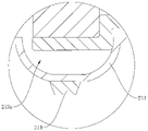
In addition to the above embodiments, in order to further increase the volume of the first heat sink 252, referring to fig. 16d, a side surface of the first section 2512e facing the internal accommodating space 21a of the electronic apparatus 100 is lower than the notch position of the accommodating groove 213a, and a side surface of the first section 2512e facing away from the accommodating space 21a is attached to the inner wall surface 212a of the accommodating groove 213 a. Specifically, a side surface of the first section 2512e facing away from the accommodating space 21a is fitted to at least one of the inner bottom wall 213a1 and the inner side wall 213a2 in the inner wall surface 213a0 of the accommodating groove 213 a. In this way, the first section 2512e can be maximally sunk into the receiving groove 213a, so that the volume of the first heat sink 252 can be further increased, and the heat dissipation efficiency can be improved.
Specifically, after the first segment 2512e is disposed in the receiving groove 213a, the height of the first heat sink 252 (i.e., the dimension of the first heat sink 252 in the Z-axis direction) can be increased, so as to increase the volume of the first heat sink 252. Illustratively, the height of the first heat sink 252 may be increased by at least 1mm to 2 mm.
It is understood that, in other embodiments, referring to fig. 16e, a side surface of the first section 2512e facing away from the receiving space 21a may be spaced apart from the inner bottom wall 213a1 of the receiving groove 213 a. In this embodiment, a side surface of the first section 2512e facing the accommodating space 21a may be flush with the notch of the accommodating groove 213a, or may be lower or higher than the notch of the accommodating groove 213 a.
On this basis, the heat dissipation module 25 may further include a second heat sink 254, the second heat sink 254 is in thermal conductive connection with the first section 2512e, and the second heat sink 254 and the first heat sink 252 are respectively located at two opposite sides of the first section 2512 e. Referring to fig. 16e, the first heat sink 252 is connected to a side surface of the first section 2512e facing the accommodating space 21a, and the second heat sink 254 is connected to a side surface of the first section 2512d facing away from the accommodating space 21 a. Thus, the space in the receiving groove 213a can be fully utilized, and the heat dissipation area can be further increased without increasing the overall thickness of the electronic device 100, thereby further improving the heat dissipation efficiency.
In order to improve the heat dissipation efficiency of the second heat sink 254, the second heat sink 254 may contact the inner bottom wall 213a1 of the receiving groove 213a, or the second heat sink 254 may contact the inner sidewall 213a2 of the receiving groove 213a, or the second heat sink 254 may contact both the inner bottom wall 213a1 and the inner sidewall 213a2 of the receiving groove 213 a. In this way, the heat on the second heat sink 254 can be transferred to the outside of the electronic device 100 through the protrusion 213, thereby improving the heat dissipation efficiency.
In some embodiments, the second heat sink 254 is a unitary structure with the first heat sink 252. Thus, the structure of the heat dissipation module 25 can be simplified, and the production efficiency and the assembly efficiency can be improved.
Of course, in other embodiments, the first heat sink 252 and the second heat sink 254 may be a split structure. In this embodiment, the second heat sink 254 may have the same structure as the first heat sink 252 or may be different from the first heat sink 52, which is not specifically limited in this application.
Based on the above embodiment, please refer to fig. 16d and fig. 16e, the protrusion 213 is provided with a first heat dissipation hole 213b communicating the accommodating groove 213a and the external space of the protrusion 213. Optionally, the first heat dissipation hole 213 is formed on a sidewall of the protrusion 213. Thus, the airflow fluidity in the accommodating groove 213a can be improved, and the heat on the first heat sink 252 or the second heat sink 254 located in the accommodating groove 213a can be discharged to the outside of the electronic device 100 through the first heat dissipation hole 213b, thereby further improving the heat dissipation efficiency.
With continued reference to fig. 15-16, the thermal conductive structure 251 includes a thermal conductive fin 2511 and a thermal spreader 2512. The heat spreader 2512 is a heat pipe or a heat spreader. The heat-conducting sheet 2511 is connected to the heating element 3 by heat conduction, and the heat-conducting sheet 2511 is connected to the heat equalizer 2512 by heat conduction. Optionally, the material of the heat conducting sheet 2511 is copper. The good and ductility of metallic copper's thermal conductivity is higher, adopts metallic copper material preparation conducting strip 2511, can be when guaranteeing conducting strip 2511 thermal conductivity, makes conducting strip 2511 thin, has reduced conducting strip 2511's occupation space, can compromise the radiating efficiency and the frivolous design of electronic equipment 100 simultaneously.
Referring to fig. 15, the heat conducting sheet 2511 may be formed in a rectangular sheet structure, and an orthographic projection of the heating element 3 on a plane where the heat conducting sheet 2511 is located may be located in the heat conducting sheet 2511. In this way, the contact area between the heat generating element 3 and the heat conducting structure 251 can be increased, so that the heat on the heat generating element 3 can be rapidly transferred to the first heat sink 252 through the heat conducting structure 251, which is beneficial to improving the heat dissipation efficiency.
It is understood that, in other embodiments, the heat-conducting sheet 2511 may also be formed in an oval, circular, racetrack-shaped structure, and the specific shape of the heat-conducting sheet 2511 is not limited in this application.
Referring back to fig. 13, the heat-conducting sheet 2511 is fixed on the motherboard 24 and is connected to the CPU, GPU, etc. on the motherboard 24 in a heat-conducting manner. Opposite side surfaces of the heat-conducting sheet 2511 are connected to the soaking member 2512 and the heating element 3, respectively. Illustratively, the heat-conducting fins 2511 may be fixed to the main board 24 by gluing, clamping, screwing, or the like.
Referring to fig. 17a, fig. 17a is a perspective view of the heat spreader 2512 in the heat dissipation module 25 shown in fig. 15. The heat spreader 2512 includes an evaporation section 2512d and a condensation section, and the evaporation section 2512d and the condensation section are respectively located at two ends of the heat spreader 2512 in the extending direction. The condensing section is formed as the first section 2512e described above. Illustratively, the condensation section of heat spreader 2512 extends along the X-axis and evaporation section 2512d extends along the Y-axis. The evaporation section 2512d is connected to the heating element 3 in a heat conduction manner, and the condensation section is connected to the first heat sink 252 in a heat conduction manner. That is, both ends of the soaking member 2512 in the extending direction are thermally conductively connected to the first heat sink 252 and the heat-conducting fin 2511, respectively.
In order to improve the heat conduction efficiency between the heat spreader 2512 and the first heat sink 252, in some embodiments, please refer to fig. 17b, and fig. 17b is a perspective view of the heat dissipation module 25 according to another embodiment. In this embodiment, the free end of the first section 2512e (i.e., the condenser section) is provided with a flange 2512e1, and the first heat sink 252 is in heat-conducting connection with the flange 2512 e. In this way, the contact area between the first heat spreader 252 and the heat spreader 2512 can be increased, and the heat conduction efficiency between the first heat spreader 252 and the heat spreader 2512 can be increased.
In some embodiments, referring to fig. 18a, fig. 18a is a cross-sectional view taken along line B-B of fig. 17 a. In this embodiment, the heat spreader 2512 is a heat pipe. The heat pipe includes a case 2512a, a wick 2512b, and an end cap 2512c, where the case 2512a is formed in a hollow structure and the wick 2512b covers the inner wall of the case 2512 a. After the tube is pumped to negative pressure, a proper amount of working liquid 2512g is filled in the tube, so that the capillary porous material of the wick 2512b tightly attached to the inner wall of the tube is filled with the liquid, and then the capillary porous material is sealed through the end cover 2512 c. When one end (i.e., the evaporation section 2512d) of the heat pipe is heated, the liquid in the wick 2512b evaporates and vaporizes, the vapor flows to the other end (i.e., the condensation section) under a slight pressure difference to release heat and condense into liquid, and the liquid flows back to the evaporation section 2512d along the porous material under the action of capillary force. This cycle operation achieves a rapid heat transfer effect, and the heat is uniformly distributed to the first heat sink 252, and then the heat is dissipated through the air, thereby improving the heat dissipation efficiency of the electronic device 100 to a certain extent.
In other embodiments, thermal spreader 2512 can also be a thermal spreader. The vapor chamber is a vacuum chamber with a fine structure on the inner wall, usually made of copper, and the inside of the vacuum chamber is filled with a cooling liquid. When heat is conducted to the evaporation section 2512d from the heat source, the coolant in the vacuum cavity starts to generate a gasification phenomenon after being heated in a low-vacuum-degree environment, at the moment, heat energy is absorbed, the volume rapidly expands, the whole vacuum cavity is rapidly filled with gaseous cooling medium, and a condensation phenomenon can be generated when the gaseous working medium contacts a relatively cold region. The heat accumulated during evaporation is released by the condensation phenomenon, and the condensed cooling liquid returns to the evaporation heat source by the capillary tube of the microstructure, and the operation is repeated in the cavity to achieve a rapid heat transfer effect, and is uniformly distributed to the first heat sink 252, and then the heat energy is dissipated by air, so that the heat dissipation efficiency of the electronic device 100 can be improved to a certain extent.
To facilitate the assembly of the heat spreader 2512, referring to fig. 17a, a level difference 2512f is formed by bending the evaporation level 2512d and the condensation level of the heat spreader 2512 such that the evaporation level 2512d and the condensation level are at different heights. Like this, when the assembly, can set up the condensation segment of soaking 2512 in storage tank 213a, the assembly of soaking 2512 of being convenient for can guarantee the heat-conduction between evaporation zone 2512d and the heating element 3 simultaneously and be connected, has reduced the assembly degree of difficulty, is favorable to improving assembly efficiency.
In some embodiments, the first heat spreader 252 may be in thermally conductive connection with the stepped portion 2512 f. In this way, the contact area between the first heat spreader 2512f and the heat spreader 2512 can be increased, and the heat conduction efficiency between the first heat spreader 252 and the heat spreader 2512 can be increased.
In some embodiments, referring to fig. 17 a-18 a, the heat pipes 2512 are formed as flat tubes. Thus, the occupied space of the heat pipe 2512 in the Z-axis direction can be reduced, which is beneficial to realizing the light and thin design of the electronic device 100.
In some embodiments, referring back to fig. 15, each of the thermal spreader 2512 and the first heat spreader 252 is two, and for convenience of description, the two thermal spreaders 2512 are respectively referred to as a "first thermal spreader" and a "second thermal spreader", and the two first heat spreaders 252 are respectively referred to as a "first sub-heat spreader" and a "second sub-heat spreader". The evaporation section 2512d of the first soaking member and the evaporation section 2512d of the second soaking member are both connected with the heat-conducting fin 2511, and the evaporation section 2512d of the first soaking member and the evaporation section 2512d of the second soaking member are spaced from each other. The condensation section of the first soaking piece and the condensation section of the second soaking piece extend towards the directions far away from each other respectively. The first sub-radiator is connected with the condensation section of the first soaking piece, and the second sub-radiator is connected with the condensation section of the second soaking piece. Thus, by providing two heat spreaders 2512 (i.e., a first heat spreader and a second heat spreader) and two first heat sinks 252 (i.e., a first sub-heat sink and a second first sub-heat sink), the heat dissipation performance of the heat dissipation module 25 can be improved, and the performance of the electronic device 100 can be improved.
In other embodiments, please refer to fig. 18b, fig. 18b is a top view of a thermal conductive structure 251 according to other embodiments of the present application. In this embodiment, the heat-conductive sheet 2511 and the heat spreader 2512 are heat spreaders. The heat-conducting fins 2511 and the heat spreader 2512 are integrated. That is, the heat-conducting sheet 2511 and the soaking member 2511 are integrally formed. Thus, the processing technology of the heat conducting structure 251 can be simplified, the processing efficiency can be improved, and the heat conducting efficiency of the heat conducting structure 251 can be ensured.
Referring to fig. 19, fig. 19 is a perspective view of the first heat sink 252 of the heat dissipation module 25 shown in fig. 15. The first heat sink 252 includes a heat dissipating substrate 252a and a plurality of heat dissipating fins 252b, the heat dissipating substrate 252a is connected to the condensation section of the heat spreader 2512 in a heat conducting manner, each heat dissipating fin 252b is fixed on the heat dissipating substrate 252a, and the plurality of heat dissipating fins 252b are arranged on the heat dissipating substrate 252a at intervals. Illustratively, the heat dissipation substrate 252a is formed in a rectangular plate-like structure. The longitudinal direction of the heat dissipation substrate 252a is parallel to the X-axis direction, the width direction of the heat dissipation substrate 252a is parallel to the Y-axis direction, and the width direction of the heat dissipation substrate 252a is parallel to the Z-axis direction. The plurality of heat dissipation fins 252b may be provided at intervals in the longitudinal direction of the heat dissipation substrate 252 a. A heat dissipation channel 252c is defined between two adjacent heat dissipation fins 252b, and when air flows through the heat dissipation channel 252c, the air can exchange heat with the heat dissipation fins 252b, so that heat on the heat dissipation fins 252b can be brought to the outside of the electronic device 100 through the air.
Alternatively, each of the heat dissipation fins 252b is disposed perpendicular to the heat dissipation substrate 252 a. In this way, the structure of the first heat sink 252 can be more compact, which is beneficial to increase the heat dissipation area of the first heat sink 252, and further can improve the heat dissipation performance of the heat dissipation module 25, so as to improve the performance of the electronic device 100.
It is understood that the heat dissipating base 252a and the heat dissipating fins 252b may be an integral structure or a separate structure. The first heat sink 252 is used to dissipate heat from the heat generating element 3, and when this requirement is satisfied, the first heat sink 252 may have another structure, and is not limited to this embodiment.
In some embodiments, please refer to fig. 20, fig. 20 is a cross-sectional view of the keyboard host 2 according to still other embodiments of the present application, a second heat dissipation hole 216 is disposed on the housing 21 of the electronic device 100 to communicate the accommodating space 21a with the exterior of the housing 21, and the second heat dissipation hole 216 may be formed on any sidewall of the housing 21. For example, referring to fig. 20, the second heat dissipation hole 216 is formed on the rear wall of the housing 21. Thus, the heat on the first heat sink 252 can be exhausted out of the electronic device 100 through the second heat dissipation hole 216. In other embodiments, the electronic device 100 may not have the second heat dissipation hole 216, and at this time, the heat on the first heat sink 252 may be dissipated to the outside of the electronic device 100 through the assembly gap of the electronic device 100.
On this basis, in order to further improve the heat dissipation performance of the heat dissipation module 25, please refer to fig. 20-21, fig. 21 is a schematic structural view of the internal structure of the keyboard main unit 2 shown in fig. 20, as viewed from top to bottom. The housing 21 of the keyboard main unit 2 in this embodiment is further provided with an air inlet 215 communicating the accommodating space 21a with the outside of the electronic device 100, and the first heat sink 252 is disposed between the air inlet 215 and the second heat dissipating hole 216. Thus, after entering the accommodating space 21a from the air inlet 215, the external air flow exchanges heat with the first heat sink 252, and the air flow after heat exchange is discharged to the outside of the electronic device 100 through the second heat dissipation hole 216. This improves the air flow fluidity of the housing space 21a, and improves the heat dissipation performance of the heat dissipation module 25.
Specifically, the air inlet 215 and the protruding portion 213 are formed on the same side surface of the housing 21. For example, referring to fig. 21, the air inlet 215 and the protrusion 213 are formed on the bottom surface of the keyboard main body 2, the protrusion 213 is disposed near the rear end of the keyboard main body 2, and the air inlet 215 is located at the front side of the protrusion 213. Illustratively, the intake vent 215 includes a plurality of intake vents 2151 spaced apart in the X-axis direction. Thus, when the protruding portion 213 contacts the supporting surface for placing the electronic device 100, the airflow can enter the accommodating space 21a from the air inlet space between the protruding portion 213 and the supporting surface through the air inlet 215, which not only increases the airflow in the accommodating space 21a, but also hides the air inlet 215 at the bottom of the housing 21, thereby improving the appearance of the electronic device 100.
On this basis, in order to further improve the heat dissipation performance of the heat dissipation module 25, please refer to fig. 22, and fig. 22 is a perspective view of the heat dissipation module 25 according to some further embodiments of the present application. The difference between the heat dissipation module 25 in this embodiment and the heat dissipation module 25 shown in fig. 15 is that: the thermal module 25 in this embodiment includes a fan 253, in addition to the heat conducting structure 251 and the first heat sink 252 of the thermal module 25 shown in fig. 15, the fan 253 has a fan inlet and a fan outlet.
Referring to fig. 23, fig. 23 is an assembly diagram of the heat dissipation module 25 shown in fig. 15 on the keyboard host 2. The fan 253 is disposed in the accommodating space 21a, an inlet of the fan is communicated with the air inlet 215, an outlet of the fan is communicated with the second heat dissipating hole 216, and the first heat sink 252 is disposed between the outlet of the fan and the second heat dissipating hole 216. The fan 253 is used for driving the airflow to flow from the air inlet 215 to the second heat dissipation hole 216. Thus, under the driving of the fan 253, the airflow enters the accommodating space 21a from the air inlet 215, flows to the fan outlet through the fan inlet of the fan 253, and flows to the second heat dissipation hole 216 after exchanging heat with the first heat sink 252, and is discharged to the outside of the electronic device 100 through the second heat dissipation hole 216. Thus, by providing the fan 253, the airflow flow rate in the accommodating space 21a can be increased, and the heat radiation performance of the heat radiation module 25 can be improved.
In addition, according to the electronic device 100 provided in the embodiment of the present application, since the heat conducting structure 251 sinks into the accommodating groove along with the heat conducting connection portion of the first heat sink 252, blocking of the fan outlet by the heat conducting structure 251 is reduced, an effective air outlet area of the fan outlet is increased, that is, an area of the fan outlet opposite to the first heat sink 252 is increased, flow resistance of air flow is reduced, and improvement of air volume and heat dissipation performance is facilitated.
Optionally, the fan outlet is disposed opposite to the second heat dissipation hole 216. That is, the orthographic projection of the fan outlet on the plane of the second heat dissipation hole 216 overlaps with the air outlet. Thus, the airflow blown out from the fan outlet can directly blow to the second heat dissipation hole 216 after exchanging heat with the first heat sink 252, thereby reducing the flow resistance of the airflow and being beneficial to reducing the noise of the heat dissipation module 25. Meanwhile, the heat exchange efficiency between the airflow and the first heat sink 252 can be improved, and the heat dissipation performance of the heat dissipation module 25 is further improved.
In the description herein, particular features, structures, materials, or characteristics may be combined in any suitable manner in any one or more embodiments or examples.
Finally, it should be noted that: the above embodiments are only used to illustrate the technical solutions of the present application, and not to limit the same; although the present application has been described in detail with reference to the foregoing embodiments, it should be understood by those of ordinary skill in the art that: the technical solutions described in the foregoing embodiments may still be modified, or some technical features may be equivalently replaced; and such modifications or substitutions do not depart from the spirit and scope of the corresponding technical solutions in the embodiments of the present application.