CN114978796A - Method for operating a communication system, communication system and computing system - Google Patents
Method for operating a communication system, communication system and computing system Download PDFInfo
- Publication number
- CN114978796A CN114978796A CN202210165606.5A CN202210165606A CN114978796A CN 114978796 A CN114978796 A CN 114978796A CN 202210165606 A CN202210165606 A CN 202210165606A CN 114978796 A CN114978796 A CN 114978796A
- Authority
- CN
- China
- Prior art keywords
- communication system
- configuration table
- communication
- intermediate controller
- computing system
- Prior art date
- Legal status (The legal status is an assumption and is not a legal conclusion. Google has not performed a legal analysis and makes no representation as to the accuracy of the status listed.)
- Pending
Links
Images


Classifications
-
- H—ELECTRICITY
- H04—ELECTRIC COMMUNICATION TECHNIQUE
- H04L—TRANSMISSION OF DIGITAL INFORMATION, e.g. TELEGRAPHIC COMMUNICATION
- H04L12/00—Data switching networks
- H04L12/28—Data switching networks characterised by path configuration, e.g. LAN [Local Area Networks] or WAN [Wide Area Networks]
- H04L12/40—Bus networks
- H04L12/40006—Architecture of a communication node
- H04L12/40032—Details regarding a bus interface enhancer
-
- H—ELECTRICITY
- H04—ELECTRIC COMMUNICATION TECHNIQUE
- H04L—TRANSMISSION OF DIGITAL INFORMATION, e.g. TELEGRAPHIC COMMUNICATION
- H04L12/00—Data switching networks
- H04L12/28—Data switching networks characterised by path configuration, e.g. LAN [Local Area Networks] or WAN [Wide Area Networks]
- H04L12/44—Star or tree networks
-
- H—ELECTRICITY
- H04—ELECTRIC COMMUNICATION TECHNIQUE
- H04L—TRANSMISSION OF DIGITAL INFORMATION, e.g. TELEGRAPHIC COMMUNICATION
- H04L12/00—Data switching networks
- H04L12/28—Data switching networks characterised by path configuration, e.g. LAN [Local Area Networks] or WAN [Wide Area Networks]
- H04L12/40—Bus networks
- H04L12/40006—Architecture of a communication node
- H04L12/40039—Details regarding the setting of the power status of a node according to activity on the bus
-
- H—ELECTRICITY
- H04—ELECTRIC COMMUNICATION TECHNIQUE
- H04L—TRANSMISSION OF DIGITAL INFORMATION, e.g. TELEGRAPHIC COMMUNICATION
- H04L12/00—Data switching networks
- H04L12/28—Data switching networks characterised by path configuration, e.g. LAN [Local Area Networks] or WAN [Wide Area Networks]
- H04L12/40—Bus networks
- H04L12/403—Bus networks with centralised control, e.g. polling
-
- H—ELECTRICITY
- H04—ELECTRIC COMMUNICATION TECHNIQUE
- H04L—TRANSMISSION OF DIGITAL INFORMATION, e.g. TELEGRAPHIC COMMUNICATION
- H04L12/00—Data switching networks
- H04L12/28—Data switching networks characterised by path configuration, e.g. LAN [Local Area Networks] or WAN [Wide Area Networks]
- H04L12/40—Bus networks
- H04L2012/40208—Bus networks characterized by the use of a particular bus standard
- H04L2012/40234—Local Interconnect Network LIN
-
- H—ELECTRICITY
- H04—ELECTRIC COMMUNICATION TECHNIQUE
- H04L—TRANSMISSION OF DIGITAL INFORMATION, e.g. TELEGRAPHIC COMMUNICATION
- H04L12/00—Data switching networks
- H04L12/28—Data switching networks characterised by path configuration, e.g. LAN [Local Area Networks] or WAN [Wide Area Networks]
- H04L12/40—Bus networks
- H04L2012/40267—Bus for use in transportation systems
- H04L2012/40273—Bus for use in transportation systems the transportation system being a vehicle
-
- H—ELECTRICITY
- H04—ELECTRIC COMMUNICATION TECHNIQUE
- H04L—TRANSMISSION OF DIGITAL INFORMATION, e.g. TELEGRAPHIC COMMUNICATION
- H04L67/00—Network arrangements or protocols for supporting network services or applications
- H04L67/01—Protocols
- H04L67/12—Protocols specially adapted for proprietary or special-purpose networking environments, e.g. medical networks, sensor networks, networks in vehicles or remote metering networks
Landscapes
- Engineering & Computer Science (AREA)
- Computer Networks & Wireless Communication (AREA)
- Signal Processing (AREA)
- Health & Medical Sciences (AREA)
- Computing Systems (AREA)
- General Health & Medical Sciences (AREA)
- Medical Informatics (AREA)
- Small-Scale Networks (AREA)
Abstract
The invention relates to a method for operating a communication network having a computing system, at least one intermediate controller and at least one execution unit of each intermediate controller, wherein at least one intermediate controller is communicatively connected to the computing system by means of a first communication system, at least one execution unit is communicatively connected to the assigned intermediate controller by means of a second communication system, respectively, and is used as a slave, the second communication system being a master-slave communication system, a message configuration table for each second communication system being registered in the computing system, the message configuration table specifies the chronological order of the data to be transmitted on the associated second communication system, and transmitting, by the computing system, data to one of the execution units via the associated intermediate controller in accordance with the associated message configuration table when communicating with the execution unit. The invention relates equally to a communication network, a computing system and a method for establishing a communication network.
Description
Technical Field
The present invention relates to a method for operating a communication system, to a communication system and to a method for setting up a communication system.
Background
In modern vehicles, there are a large variety of functions which are implemented by means of individual controllers and sensors and actuators connected thereto. The communication connection of the sensors and actuators to the controller can be realized, for example, by means of a LIN bus. The controllers can in turn be connected to each other in a data transmission manner or in a communication manner in order to exchange data or information. The totality of the controllers, sensors and actuators and, if appropriate, further components such as, in particular, communication connections, is also referred to as an on-board network or on-board data network, the structure or arrangement of which is also referred to as the E/E architecture.
Disclosure of Invention
According to the invention, a method for operating a communication system, a communication system and a method for setting up a communication system are proposed with the features of the independent patent claims. Advantageous embodiments are the subject matter of the dependent claims and the subsequent description.
The present invention relates to a communication network, such as an in-vehicle network or E/E architecture in a vehicle, and in particular to communication between various units in the communication network or in-vehicle network. A special aspect here consists in the use of a LIN bus or other master-slave communication system, that is to say a communication system with a communication master subscriber and one or more communication slave subscribers, and the integration thereof.
Vehicle manufacturers are striving to optimize E/E architectures, among other things, driven by cost optimization, increased complexity of electronics in the vehicle, and new possibilities due to technological advances. In order to save costs by simplifying the cable harness on the one hand and to increase flexibility and scalability by concentrating the software on a so-called Vehicle central Computer (also called "Vehicle Computer") on the other hand, the use of a so-called area E/E architecture or area architecture is considered. In the zone E/E architecture, for example, sensors, actuators and also other units can be connected to one or more vehicle central computers via so-called zone controllers depending on their geometric position in the vehicle. In this case, the zone controllers act in particular as energy and data distributors, the actual logic or functions being executed or calculated at least as far as possible on the vehicle central computer.
The concentration of the software (with logic and functionality) is usually accompanied by a more functional computing unit on the vehicle central computer — the microcontroller (μ C) based systems that are common today are expanded in this device category with a microprocessor (μ P). Operating systems (for example, POSIX-based operating systems) running thereon can implement, for example, a so-called service-oriented architecture (SOA), which allows efficient and rapid development of functions.
In the case of the mentioned regional architecture, three layers (or "layers") are provided: a compute Layer (or "Computational Layer"), a zone Layer (or "Zonal Layer"), and an execute or embed Layer (or "Embedded Layer"). In this case, a vehicle central computer is provided on the computing layer. It is also conceivable to use a plurality of such vehicle central computers, which are then correspondingly assigned to the computing layer in their entirety. Typically and preferably also, the vehicle central computer is connected (in particular wirelessly) to a computing unit outside the vehicle, such as a remote computing system or server ("Cloud"), via which various functions or services can be provided or also software updates can be provided. In the case of a plurality of vehicle central computers, it may be sufficient to connect one of the vehicle central computers to a computing unit outside the vehicle. Subsequently, the computing unit outside the vehicle can likewise be assigned to the computing layer.
At the zone level, zone controllers are provided (in a general sense), wherein there are usually a plurality of zone controllers, although the zone architecture can in principle also be applied in the case of only one zone controller. At the execution level, execution units are provided (in a general sense), wherein usually a plurality of execution units are present per zone controller, although the zone architecture can in principle also be applied in the case of a total of only one execution unit or one execution unit per zone controller.
These zone controllers, as also explained in more detail below, are relatively simple computing systems or computing units, in particular for geometric or spatial division in vehicles. For example, four zone controllers may be provided, one for each of the front, rear, left and right in the vehicle (see also the figures with the description of the figures for this purpose). The actuating Units are in particular sensors, actuators, "smart" mechatronics or mechatronics Units (so-called smart components, which refer to mechanical Units with their own computer logic or their own controllers, such as the cooler mechatronics consisting of a fan motor, a fan output stage and a fan microcontroller, or the transmission mechatronics, which regulates the shifting process, for example), and also (smart) "Electronic Control Units" (ECUs), i.e. controllers in the conventional sense, and other mechatronics Units, which are at the lowest level and are responsible for (directly) executing actions or measurements. Since the execution units are respectively assigned to the zone controllers, the respective execution units can also be assigned correspondingly to, for example, "front" or "rear" zones. For example, all controllers disposed within the engine compartment may be assigned to the "front" zone.
In this case, the zone controllers are each communicatively connected to a vehicle central computer (or computing layer) by means of a first communication system. Here, for example, an ethernet or other broadband communication system is considered as the first communication system. In the case of a plurality of vehicle central computers, each zone controller can be connected to (only) one of the vehicle central computers. The execution units are each communicatively connected, indirectly or directly, via a second communication system, such as a communication bus, to the zone controllers assigned to the execution units. Here, for example, a CAN or LIN bus is considered as the second communication system or communication bus. In this case, different execution units can also be connected to the same local controller, if necessary, via different communication buses. In this case, the individual actuating units can be connected directly to the assigned zone controller, which is particularly suitable for controllers or smart sensors and actuators. However, the execution unit may also be connected indirectly to the zone controller, for example via such a controller. This then applies in particular to simple sensors and actuators. Here, a communication connection is to be understood to mean, in particular, for all communication systems: data or information can be exchanged, in particular digitally (but also if necessary in the case of simple sensors in an analog manner).
The invention now relates in particular to the second communication system, which can be used in the local architecture if it is based on master-slave communication, in particular to the LIN bus. The communication master subscriber specifies the time sequence of the communication in that it sends out messages (or frames) which the communication slave subscriber fills with data according to specific configuration rules, or to which the communication slave subscriber attaches their data.
The invention shall be described subsequently in particular with regard to a LIN bus, but the principle can also be transferred to other systems based on master-slave communication. Here, LIN stands for "Local Interconnect Network", and is a serial communication system, i.e., a field bus, used for networking of, for example, sensors and actuators. A typical example of an application is, for example, networking in a door or a seat of a motor vehicle.
In principle, one or more LIN buses may be connected to the controller, wherein one or more further units, such as actuators and sensors (or in general execution units, in the above example) may be connected to each of these LIN buses. The units are used here as slaves, while the controller is used as master, wherein a separate master is provided here for each LIN bus in the controller. The connection between the individual LIN buses or other buses (such as CAN), at least in conventional architectures, CAN be established by means of gateway software on the controller or between different controllers.
As already mentioned at the outset, in vehicles, a plurality of LIN buses are usually present at different controllers, which are connected via a gateway. The scheduling of LIN clusters can thereby also be coordinated if the operating systems of these controllers are synchronized in time. These schedules are configuration tables (also referred to as message configuration tables hereinafter) for messages or notifications to be transmitted or received, which are present on the relevant controllers (hosts) and according to which the hosts coordinate the communication on the LIN bus. In this case, within a frame, the master first sends a header in a way that mainly specifies which slave/slaves, for example, have a message to send and which slave/slaves have a message to receive. Then, based on the header, data may be sent in a reply by the slave. The host itself may also send and receive data.
In addition, in particular in the case of a LIN bus, a normal operating mode ("normal" or "wake") and a sleep mode ("sleep") are provided as operating modes. Communication is performed in a normal operation mode. However, the master can put the slave in sleep mode (by means of a specific message), again typically providing: these units are switched to sleep mode after a certain time of no activity on the LIN bus. The master and also each slave can put the LIN bus from the sleep mode into the normal operating mode (by means of a "wake up signal", also referred to as activation). These units are then typically initialized and the units are ready for communication. The specific method for switching between operating modes may be specified in a configuration table that resides on the host or an associated controller. In this operating mode configuration table, a plurality of LIN buses of the controller may also be included. Hereinafter, the configuration table for a specific operation mode is referred to as an operation mode configuration table.
In the case of the above-mentioned local architecture, the communication via the LIN bus should be integrated as optimally as possible. The vehicle central computer mentioned here can be, for example, a gateway, via which a plurality of LIN buses can be connected. Although vehicle central computers provide good or high computing power, they also have high latency and often have limited real-time capabilities. Here, the response time is typically about 100ms, for example, which roughly corresponds to one period of the LIN schedule (e.g., 10 time slots (or frames), each having 10 ms). Although these zone controllers have a low computing power, they have a good real-time capability for this purpose, with a response time of, for example, between approximately 1 ms and 10 ms, which corresponds approximately to one time slot of the LIN schedule. Furthermore, the zone controllers usually have a plurality of communication interfaces (for connection to downstream actuators such as sensors and actuators) with low and medium bandwidths, whereas the vehicle central computer usually has a small number of communication interfaces with high bandwidths, such as ethernet.
If the execution units to be connected via the LIN bus are now connected to these zone controllers, which, as before, have message and operating mode configuration tables and act as masters, only low real-time requirements have to be imposed on the vehicle central computer. Although this corresponds in principle to the characteristics of a central computer of a vehicle, it is disadvantageous in this case that: the configuration of the individual LIN buses has to be carried out individually in these regions, which is relatively complicated. It would also be conceivable to: the LIN bus is connected directly to the vehicle central computer, if necessary if the circuit is simply formed by passing through these zone controllers. However, in this case, it is disadvantageous: these vehicle central computers do not have particularly good real-time capabilities, but this is important for LIN.
Against this background, it is now proposed within the scope of the invention: in the case of the above-described regional architecture with a vehicle central computer, a regional controller and an execution unit connected thereto via a master-slave communication system, a message configuration table for the relevant master-slave communication system is registered in the vehicle central computer, with the data being sent by the vehicle central computer to the execution unit via the regional controller in accordance with the message configuration table when communicating with the execution unit. Here, the message configuration table describes: which messages or notifications (headers/replies) should be sent by which subscriber (master/slave) when and/or with what frequency. That is, the message configuration table specifies the chronological order of the data to be transmitted on the associated second communication system (e.g. LIN). The second communication system must comply with these times according to the protocol specifications. The vehicle central computer can and in particular must allocate one or more messages and, if necessary, the configuration of said messages in time before the second communication system requires them.
In this way, the high computing power of the vehicle central computer is combined with the short delay times of the zone controllers. The vehicle central computer can thereby use a wide range of communication interfaces, i.e. in particular a plurality of master-slave communication systems, such as the LIN bus at the zone controllers, but is not affected by the delay requirements of these communication interfaces. Further, these zone controllers do not require extensive configuration information or application software. The functions of the master of all master-slave communication systems connected to the vehicle central computer via the optionally multiple zone controllers are thereby assumed by the vehicle central computer, at least with regard to the transmission and reception of data.
The operating mode configuration table (or operating mode configuration, as it is also referred to) can preferably also be registered on the vehicle central computer, which then has full control, i.e. for example also a sleep mode of the LIN bus can be initiated. However, the operating mode configuration tables may also continue on the zone controllers. However, here, a simple wake-up configuration at these zone controllers is in principle sufficient to enable wake-up by the slave controllers (i.e. in particular the execution units).
The request for sleep state is typically implemented either by notification or by bus idle (typically over 4 s). The host implicitly wakes up the bus by each send or receive notification.
The subscriber on the LIN bus (or in the second communication system) is activated by a defined wake-up notification. If the operating mode is configured in the zone controller, the host in this zone controller checks the wake-up authorization by querying the authorized bus subscribers (on the second communication system), since at this point in time no connection to the vehicle central computer has yet been ensured. Once the connection to the vehicle central computer is established, a notification (or message) of the check is forwarded to it as well. The advantage of this method is that the quiescent current requirement is low, since the vehicle central computer does not have to be activated for checking the wake-up authorization. If the operating mode is configured in the vehicle central computer, this is first activated and the wake-up authorization is checked by sending or receiving a notification. The disadvantage is a longer wake-up time and a higher quiescent current requirement, in particular in the presence of interference, while the advantage is a simple configuration in the zone controller. That is, the operating mode configuration or the operating mode configuration table specifies the wake-up authorizations of the second communication system (or LIN bus) and/or the checking of these wake-up authorizations.
For this purpose, the data to be transmitted from the vehicle central computer to the actuating unit are transmitted, in particular, together with the transmission time to the relevant zone controller and are transmitted from the zone controller to the actuating unit at the transmission time as transmission data. Such transmitted data may comprise, for example, a message header or also the header together with the useful data (if the host also wants to send data to itself here). The data sent from the execution unit (as a slave) are preferably received by the zone controller and transmitted as received data to the vehicle central computer together with the time of reception. The data obtained in this way can also be distributed and processed correspondingly by the vehicle central computer on account of the message configuration table present in the latter. From the perspective of the vehicle central computer, the vehicle central computer thereby manages the global master-slave communication system, like a large virtual LIN bus.
Although this type of integration of the master-slave communication system is particularly well suited for the regional architecture in vehicles, according to which the invention has been explained above, the method can also be used in other communication networks in which the execution units are connected as slaves to a controller or intermediate controller, which is in turn connected via a communication system such as ethernet to a higher-level computing system (preferably with high computing capacity, which then corresponds in particular to a vehicle central computer). Here, a simple extension to the use of a plurality of controllers (in the case of zone controllers) and a plurality of master-slave communication systems having one or more execution units each therein is also possible.
In addition to a method for operating such a communication network, in particular as a vehicle network in a vehicle, the invention also relates to such a communication network, to a computing system for use in such a communication network, and to a method for establishing such a communication network. For further design considerations and advantages of communication networks, computing systems, and building methodologies, reference should be made to the above statements, which apply correspondingly herein, to avoid repetition.
Further advantages and embodiments of the invention emerge from the description and the accompanying drawings.
The invention is schematically illustrated in the drawings and will be described below with reference to the drawings according to embodiments.
Drawings
Fig. 1 schematically shows an on-board network in a vehicle for illustrating the invention.
Fig. 2 schematically shows the regional architecture of an in-vehicle network for illustrating the invention.
Fig. 3 schematically shows a controller not according to the invention for illustrating the background of the invention.
Fig. 4 schematically shows a communication network in a preferred embodiment according to the present invention.
Fig. 5 schematically shows a communication network according to the invention in a further preferred embodiment.
Fig. 6 schematically shows a flow of a method according to the invention in a preferred embodiment.
Detailed Description
In fig. 1, a vehicle-mounted network 100 in a vehicle 102 is schematically shown for illustrating the invention, according to which the E/E architecture or distribution of the individual units or components of the vehicle-mounted network is intended to be illustrated. The on-board network 100 comprises, by way of example, a vehicle central computer 110, four controllers 120A, 120B, 120C, 120D designed as (or used as) zone controllers, and a plurality of execution units, which here comprise the controller 120, the smart mechatronic unit 132, and actuators and sensors 134 (actuators and sensors are not to be distinguished here).
The zone controllers 120A, 120B, 120C, 120D are illustratively assigned to the "front", "rear", "left" and "right" zones, respectively, and are communicatively connected to the vehicle central computer 110 via a first communication network 112, e.g., ethernet, respectively, which allows each of these zone controllers to communicate with the vehicle central computer 110, respectively. The vehicle central computer 110 also has a wireless communication interface 114 (or a corresponding communication module) in order, for example, to be able to communicate with a computing unit ("cloud") outside the vehicle, as will be explained in more detail later on.
The execution units 130, 132, 134 are each assigned to one of these zone controllers and are connected to the relevant zone controller indirectly or directly in a communicative manner via a second communication connection 122, such as a CAN or LIN bus. For example, the controller 130 assigned to the zone controller 120A is directly connected to the zone controller, while one of the sensors/actuators 134 is indirectly connected to the zone controller, i.e., via the controller 130; the sensor/actuator 134 is in particular directly connected to the controller 130. Other sensors/actuators 134 are also connected directly to the zone controller, for example, the same applies to the intelligent mechatronic unit 132.
The second communication systems 112 for connecting the execution units to the zone controllers or, if appropriate, to one another, do not all have to be identical, and a distinction according to the type of execution unit is conceivable. In this way, simpler sensors are connected, for example, only via LIN, and more complex controllers are connected, for example, via CAN. However, the zone controller has a corresponding interface.
The particular type or function of the execution units 130, 132, 134 is not important to the present invention; the actuating units 130, 132, 134, which are assigned, for example, to the zone controller 120A and thus to the "front" zones, may comprise, for example, lights or actuators for wipers or the like. A similar situation applies to the zone controller 120B or "back" zone. The actuating units assigned to the zone controllers 120C, 120D or the "left" and "right" zones can be, for example, buttons and actuators for a window regulator. At this point it should be mentioned again that: the in-vehicle network is purely exemplary and is intended to illustrate the invention.
However, the illustrated in-vehicle network 100 clearly shows: by means of these zone controllers, individual execution units can be assigned or divided in a targeted manner according to their geometric area with only one vehicle central computer (or possibly several vehicle central computers), as a result of which the total (cumulative) length of the cables for the on-board network can sometimes be significantly reduced compared to conventional E/E architectures.
Mention should be made at this point of: this relates in particular to communication systems or communication media. It is easy to understand that: an energy supply or power supply is also required for the individual units, which energy supply or power supply is not described in detail here.
The regional architecture of the on-board network is schematically shown in fig. 2 for illustrating the invention. The in-vehicle network shown here is similar to the in-vehicle network 100 in fig. 1, but the number of the respective units varies slightly; but the names correspond to those in figure 1. Thus, for example, only three zone controllers 120A, 120B, 120C are shown, each of which is assigned an execution unit, the number of which may differ from that in fig. 1. However, this has no influence on the working principle of the present invention.
As already mentioned, this area architecture has three layers, to which the individual cells are assigned. The vehicle central computer 110, which is illustrated here by way of example by a microcontroller 116 and a microprocessor 118, is assigned to the computing layer R. Also shown is a computing unit 140 outside the vehicle (e.g., a central server or central high-performance server located remotely from the vehicle that provides memory and computing power) to which the vehicle central computer is connected via a wireless communication connection 114. A computing unit 140 outside the vehicle is likewise assigned to the computing layer R.
The zone controllers 120A, 120B, 120C are assigned to the compute layer Z and the execution units 130, 132, 134 are assigned to the execute or embed layer E. Within the executive level E, the controller 130 and the smart mechatronic unit 132 are arranged at an intermediate level above the sensor/actuator 134, but this has no effect on the working principle of the invention.
With the communication system and the communication connections already described in relation to fig. 1, the following communication design results: the communication between the execution unit (at the execution level E) and the vehicle central computer (at the computation level R) is always or exclusively realized by the zone controller (at the zone level Z). The communication between the two zone controllers is then always or exclusively realized by the computation layer R. Whereby the zone controllers themselves act as only one kind of gateway or tunnel. Each zone controller outputs the input data again in a content-invariant manner, but performs adaptation in the form of other communication systems, for example from LIN to ethernet or from ethernet to CAN, or performs encapsulation.
Of particular interest within the scope of the present invention are those execution units 130, 132, 134 which are connected to the zone controller by means of a master-slave communication system, here a LIN, or by means of a LIN bus. As already mentioned, this design can also be applied to other communication networks in which one or more execution units are connected via a LIN (or similar system) to a controller, which in turn is connected to a higher-level computing system.
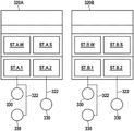
In fig. 3, non-according to the invention controllers 320A, 320B are schematically shown for illustrating the background of the invention. Here, it is intended to illustrate the conventional connection of the units to the controller via the LIN as a master-slave communication system.
In the exemplary case, three actuating units 330 are connected via two LIN buses 322 to each of two controllers, which can act, for example, as a domain controller in the vehicle. For example, two execution units are connected to each controller on one of the two LIN buses, and one execution unit is connected to each controller on the other of the two LIN buses. It is easy to understand that: this is purely exemplary and is for illustration only. As long as the actuating units 330 are connected by means of LIN, these can be, for example, sensors and actuators (also different sensors and actuators), as described above (see actuating units 130, 132, 134). These execution units are connected as slaves to the associated LIN bus, with controllers 320A, 320B acting as masters, respectively.
Correspondingly, message configuration Tables ("Scheduling Tables") st.a.1 and st.a.2 are registered in the controller 320A, and message configuration Tables st.b.1 and st.b.2 are registered in the controller 320B. At least one such message configuration table is usually present for each LIN bus connected to the controller in order to be able to control the communication. The message configuration table specifies the chronological order of the data to be transmitted on the relevant LIN bus, i.e. when, for example, a header should always be transmitted, when, for example, an acknowledgement should always be transmitted, which slave should or should be allowed to transmit, etc. In addition, an operating mode configuration table st.a.w or st.b.w for the normal mode ("Wake up") and an operating mode configuration table st.a.s or st.b.s for the Sleep mode ("Sleep") are registered in each of these controllers. This can control, for example, the activation or the wake-up of the LIN bus. The operating mode configuration table illustrates: how and/or when the operating mode is switched or should be switched, i.e. for example when the master has to send a wake-up command or how to check the wake-up authorization of the slave.
Within the scope of the invention, it is now proposed to integrate the message configuration table into a (powerful) computing system, such as a vehicle central computer, to which the LIN bus is connected, although it is still connected to the controllers, via ethernet, for example.
Fig. 4 schematically shows a communication network 400 according to the invention in a preferred embodiment. The computing system 410, which may be, for example, the vehicle central computer 110 according to fig. 1, is connected to two controllers 420A, 420B (also referred to as intermediate controllers within the scope of the invention) via a communication system 112, such as an ethernet. These controllers may be, for example, zone controllers according to fig. 1. Again, the execution unit 330 is connected to these controllers 420A, 420B by means of the LIN bus 322 as a master-slave communication system, as already described with respect to fig. 3. However, the message configuration tables st.a.1, st.a.2, st.b.1 and st.b.2 are now registered in the computing system 410, while only the operating mode configuration table is still present in these controllers 420A, 420B, as is also shown in fig. 3.
That is, the communication can be controlled by means of the computing system 410 by first sending the necessary data to the relevant controller (via, for example, ethernet, the data can be packed into the Payload (Payload) of the ethernet), in particular together with, for example, the desired sending time according to the associated message configuration table. The controller then reads these data and transmits them via the LIN bus, in particular the relevant LIN bus, at the specified point in time. Correspondingly, the controller may read the data via the LIN and package the data along with the time of receipt in the payload of the ethernet and send to the computing system 410.
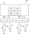
Fig. 5 schematically shows a communication network 500 according to the invention in a further preferred embodiment. The computing system 510, which may be, for example, the vehicle central computer 110 according to fig. 1, is connected to the two controllers 520A, 520B via a communication system 112, such as an ethernet. These controllers may be, for example, zone controllers according to fig. 1. A further execution unit 330 is connected to these controllers 520A, 520B by means of the LIN bus 322 as a master-slave communication system, as already described with respect to fig. 3. However, these message configuration tables, only two of which are shown here by way of example, st.1 and st.2, are now registered in computing system 510, as are the operating mode configuration tables.
That is, the communication can be controlled from the computing system 510 in that the necessary data is first sent to the relevant controller (via, for example, ethernet, the data can be packed into the payload of the ethernet), in particular together with, for example, the desired sending times according to the associated message configuration table. The controller then reads these data and transmits them via the LIN bus, in particular the relevant LIN bus, at the specified point in time. Correspondingly, the controller may read the data via the LIN and package the data together with the time of receipt in the payload of the ethernet and send to the computing system 510.
In fig. 6, a flow of a method according to the invention in a preferred embodiment is schematically shown. For this purpose, a frame 600 with a header 610 and a response 620 is first shown, as is used in LIN as a master-slave communication system.
First, computing system 410 (and possibly computing system 510) maps header 610 (the data to be transmitted) to the desired transmission time t according to the message configuration table S Sent together to the intermediate controller 420A, which then acts as a master to send the header at the time t S (this may be a point in time) is sent via the LIN to the relevant execution unit 330 as a slave. The execution unit 330 may in turn have to send a reply or response 620 as a slave according to the received header 610, for example. This response 620 is sent via the LIN to the intermediate controller 420A, which records the reception time t E And transmits the receive time point to computing system 410 along with response 620 (the data to be received).
Claims (13)
1. A method for operating a communication network (400, 500) having a computing system (410, 510), at least one intermediate controller (420A, 420B, 520A, 520B) and at least one execution unit (330) of each intermediate controller (420A, 420B, 520A, 520B),
wherein the at least one intermediate controller (420A, 420B, 520A, 520B) is communicatively connected to the computing system (410, 510) by means of a first communication system (112),
wherein the at least one execution unit (330) is connected to the assigned intermediate controller (420A, 420B, 520A, 520B) in each case in a communication manner by means of a second communication system (322) which is a master-slave communication system and is used as a slave,
wherein a message configuration table (ST.A.1, ST.A2, ST.B.1, ST.B.2, ST.1, ST.2) for each second communication system (322) is registered in the computing system (410, 510), wherein the message configuration table specifies a temporal sequence of data to be transmitted on the relevant second communication system, and wherein the message configuration table specifies a temporal sequence of data to be transmitted on the relevant second communication system
Wherein data (610) is transmitted by the computing system (410, 510) to one of the execution units (330) via the associated intermediate controller (420A, 420B, 520A, 520B) in accordance with the associated message configuration table (ST.A.1, ST.A2, ST.B.1, ST.B.2, ST.1, ST.2) when communicating with said execution unit.
2. The method of claim 1, wherein the data to be sent from the computing system (410, 510) to the execution unit (330) is associated with a sending time (t) S ) Are transmitted together to the associated intermediate controller (420A, 420B, 520A, 520B) and are transmitted as transmission data from the intermediate controller at the transmission time (t) S ) Is sent to the execution unit (330).
3. The method of claim 2, wherein the data is transmitted by the computing system (410, 510) to the associated intermediate controller (420A, 420B, 520A, 520B) in accordance with a message configuration table in a predetermined number of frames (600) at all times.
4. The method according to any of the preceding claims, wherein the data sent from the execution unit (330) is received by the belonging intermediate controller (420A, 420B, 520A, 520B) at a reception time (t |) E ) Receiving and as received data (620) and the reception time (t) E ) Are transmitted together to the computing system (410, 510).
5. The method according to one of the preceding claims, wherein an operating mode configuration table (st.a.w, st.a.s, st.b.w, st.b.s) for at least one second communication system (322) is registered in the belonging intermediate controller (420A, 420B, 520A, 520B), wherein the operating mode configuration table specifies a wake-up authorization and/or a check of the wake-up authorization of the second communication system.
6. The method according to any of claims 1 to 4, wherein a run mode configuration table (ST.W, ST.S) for at least one second communication system (322) is registered in the computing system (410, 510), wherein the run mode configuration table specifies wake-up authorizations and/or checks of the wake-up authorizations of the second communication system.
7. The method according to any of the preceding claims, wherein a LIN bus is used as the at least one second communication system (322).
8. The method according to one of the preceding claims, wherein an on-board network of the vehicle is used as the communication network, said on-board network having a vehicle central computer as the computing system (410, 510) and a zone controller as an intermediate controller.
9. A communication network (400, 500) having a computing system (410, 510), at least one intermediate controller (420A, 420B, 520A, 520B), and at least one execution unit (330) of each intermediate controller (420A, 420B, 520A, 520B),
wherein the at least one intermediate controller (420A, 420B, 520A, 520B) is communicatively connected to the computing system (410, 510) by means of a first communication system (112),
wherein the at least one execution unit (330) is each communicatively connected to an assigned intermediate controller (420A, 420B, 520A, 520B) by means of a second communication system (322) and is set up as a slave, the second communication system being a master-slave communication system,
wherein a message configuration table (ST.A.1, ST.A2, ST.B.1, ST.B.2, ST.1, ST.2) for each second communication system (322) is registered in the computing system (410, 510), wherein the message configuration table specifies a temporal sequence of data to be transmitted on the relevant second communication system, and wherein the message configuration table specifies a temporal sequence of data to be transmitted on the relevant second communication system
Wherein the communication network (400, 500) is set up such that data is transmitted by the computing system (410, 510) to one of the execution units (330) via the associated intermediate controller (420A, 420B, 520A, 520B) in accordance with the associated message configuration table (ST.A.1, ST.A2, ST.B.1, ST.B.2, ST.1, ST.2) when communicating with the execution unit (330).
10. The communication network (400, 500) according to claim 9, the communication network being set up for performing the method according to any one of claims 1 to 8.
11. A computing system (410, 510) for use in a communication network (400, 500) having the computing system, at least one intermediate controller (420A, 420B, 520A, 520B), and at least one execution unit (330) of each intermediate controller (420A, 420B, 520A, 520B),
wherein the at least one intermediate controller (420A, 420B, 520A, 520B) is communicatively connected to the computing system (410, 510) by means of a first communication system (122),
wherein the at least one execution unit (330) is each communicatively connected to an assigned intermediate controller (420A, 420B, 520A, 520B) by means of a second communication system (322) and is set up as a slave, the second communication system being a master-slave communication system,
wherein a message configuration table (ST.A.1, ST.A2, ST.B.1, ST.B.2, ST.1, ST.2) for each second communication system (322) is registered in the computing system (410, 510), wherein the message configuration table specifies a temporal sequence of data to be transmitted on the relevant second communication system, and wherein the message configuration table specifies a temporal sequence of data to be transmitted on the relevant second communication system
Wherein the computing system (410, 510) is set up such that, when communicating with one of the execution units (330), the computing system sends data to the execution unit (330) via the associated intermediate controller (420A, 420B, 520A, 520B) according to the associated message configuration table (ST.A. 1, ST.A2, ST.B.1, ST.B.2, ST.1, ST.2).
12. Method for establishing a communication network (400, 500), in particular as an on-board network in a vehicle, having a computing system (410, 510), at least one intermediate controller (420A, 420B, 520A, 520B) and at least one execution unit (330) of each intermediate controller (420A, 420B, 520A, 520B),
wherein the at least one intermediate controller (420A, 420B, 520A, 520B) is communicatively connected to the computing system (410, 510) by means of a first communication system (122),
wherein the at least one execution unit (330) is connected to the assigned intermediate controller (420A, 420B, 520A, 520B) in each case in a communication manner by means of a second communication system (322) which is a master-slave communication system and is used as a slave,
wherein a message configuration table (ST.A.1, ST.A2, ST.B.1, ST.B.2, ST.1, ST.2) for each second communication system (322) is registered in the computing system (410, 510), wherein the message configuration table specifies a temporal sequence of data to be transmitted on the relevant second communication system, and wherein the message configuration table specifies a temporal sequence of data to be transmitted on the relevant second communication system
Wherein the communication system (400, 500) is set up such that data is transmitted by the computing system to one of the execution units (330) via the associated intermediate controller (420A, 420B, 520A, 520B) in accordance with the associated message configuration table (ST.A.1, ST.A2, ST.B.1, ST.B.2, ST.1, ST.2) when communicating with said execution unit (330).
13. The method according to claim 12, for establishing a communication network (400, 500) according to any one of claims 9 to 10.
Applications Claiming Priority (2)
| Application Number | Priority Date | Filing Date | Title |
|---|---|---|---|
| DE102021104422.7A DE102021104422A1 (en) | 2021-02-24 | 2021-02-24 | Method for operating a communication system, communication system and computing system |
| DE102021104422.7 | 2021-02-24 |
Publications (1)
| Publication Number | Publication Date |
|---|---|
| CN114978796A true CN114978796A (en) | 2022-08-30 |
Family
ID=82702327
Family Applications (1)
| Application Number | Title | Priority Date | Filing Date |
|---|---|---|---|
| CN202210165606.5A Pending CN114978796A (en) | 2021-02-24 | 2022-02-23 | Method for operating a communication system, communication system and computing system |
Country Status (3)
| Country | Link |
|---|---|
| US (1) | US12278710B2 (en) |
| CN (1) | CN114978796A (en) |
| DE (1) | DE102021104422A1 (en) |
Cited By (1)
| Publication number | Priority date | Publication date | Assignee | Title |
|---|---|---|---|---|
| CN115344031A (en) * | 2022-10-19 | 2022-11-15 | 北京理工大学深圳汽车研究院(电动车辆国家工程实验室深圳研究院) | Automobile area architecture system and automobile |
Families Citing this family (3)
| Publication number | Priority date | Publication date | Assignee | Title |
|---|---|---|---|---|
| EP4113909B1 (en) * | 2021-06-30 | 2025-10-08 | Aptiv Technologies AG | A lin communication circuit and a method of communicating between lin busses |
| US20230353418A1 (en) * | 2022-04-29 | 2023-11-02 | Aptera Motors Corp. | Low latency systems and methods for vehicle communications network architecture using point of use controller |
| DE102023106897A1 (en) * | 2023-03-20 | 2024-09-26 | Bayerische Motoren Werke Aktiengesellschaft | Method for controlling vehicle electronics with a zonal architecture, method for a decentralized control unit, method for a centralized control unit, computer program, device and vehicle |
Family Cites Families (5)
| Publication number | Priority date | Publication date | Assignee | Title |
|---|---|---|---|---|
| US9172662B2 (en) * | 2010-08-04 | 2015-10-27 | Alcatel Lucent | Virtual chassis system control protocols |
| WO2012072763A1 (en) * | 2010-12-01 | 2012-06-07 | Nokia Siemens Networks Oy | Method and device for service provisioning in a communication network |
| US10355935B2 (en) * | 2014-12-09 | 2019-07-16 | Ciena Corporation | Reduced link bandwidth update systems and methods for improved scalability, efficiency, and performance |
| US12015644B2 (en) * | 2019-04-11 | 2024-06-18 | Level 3 Communications, Llc | System and method for utilization of threat data for network security |
| WO2021113305A1 (en) * | 2019-12-02 | 2021-06-10 | Excelfore Corporation | Master agent and distributed agent architecture for vehicles |
-
2021
- 2021-02-24 DE DE102021104422.7A patent/DE102021104422A1/en active Pending
-
2022
- 2022-02-17 US US17/674,109 patent/US12278710B2/en active Active
- 2022-02-23 CN CN202210165606.5A patent/CN114978796A/en active Pending
Cited By (2)
| Publication number | Priority date | Publication date | Assignee | Title |
|---|---|---|---|---|
| CN115344031A (en) * | 2022-10-19 | 2022-11-15 | 北京理工大学深圳汽车研究院(电动车辆国家工程实验室深圳研究院) | Automobile area architecture system and automobile |
| CN115344031B (en) * | 2022-10-19 | 2023-02-17 | 北京理工大学深圳汽车研究院(电动车辆国家工程实验室深圳研究院) | Automobile area architecture system and automobile |
Also Published As
| Publication number | Publication date |
|---|---|
| DE102021104422A1 (en) | 2022-08-25 |
| US12278710B2 (en) | 2025-04-15 |
| US20220271970A1 (en) | 2022-08-25 |
Similar Documents
| Publication | Publication Date | Title |
|---|---|---|
| CN114978796A (en) | Method for operating a communication system, communication system and computing system | |
| EP2208124B1 (en) | System and method for changing the state of vehicle components | |
| US7983250B2 (en) | Method and communications system for transmitting information in a motor vehicle | |
| CN114980016A (en) | Method for operating a vehicle network, vehicle network and control device | |
| US8930036B2 (en) | Reconfigurable interface-based electrical architecture | |
| Lee et al. | IEEE-1451-based smart module for in-vehicle networking systems of intelligent vehicles | |
| CN113022478B (en) | Design method of domain controller for vehicle, domain controller and vehicle | |
| JP2002368766A (en) | Wire harness system | |
| CN107920007B (en) | First communication node of a plurality of communication nodes in a vehicle network and method for operating the same | |
| JP7484687B2 (en) | In-vehicle network system | |
| CN114301946B (en) | Vehicle-mounted heterogeneous network system taking TSN as backbone network and vehicle | |
| JP2011004276A (en) | On-board network, and data transmitting method | |
| EP2571188A2 (en) | Protocol for wireless networks | |
| JP2026040744A (en) | In-vehicle device, in-vehicle system, control method, and control program | |
| JP5192353B2 (en) | Communication circuit, communication device, communication system, and communication device aggregation device | |
| JP2007336267A (en) | In-vehicle communication system | |
| CN112838970A (en) | Automobile CAN and LIN bus control system | |
| CN114980069A (en) | Method for operating a communication network, communication network and subscriber of a communication network | |
| Manoj et al. | Automotive Networks: A Review | |
| JP2019009678A (en) | In-vehicle communication network system | |
| CN114979095A (en) | Method for operating a vehicle network, vehicle network and computing system | |
| CN112550184B (en) | Centralized controller for automobile | |
| JP2002077196A (en) | Data communication system | |
| KR101165854B1 (en) | Self-Diagnosis System For MOST System | |
| EP4376388B1 (en) | Vehicle communication network |
Legal Events
| Date | Code | Title | Description |
|---|---|---|---|
| PB01 | Publication | ||
| PB01 | Publication | ||
| SE01 | Entry into force of request for substantive examination | ||
| SE01 | Entry into force of request for substantive examination |