Detailed Description
In the field of communications technology, a communication device (e.g., a terminal device, a base station, etc.) may perform channel coding by means of a polar code. Polar coding is described below in two ways.
The first method is as follows: and encoding the bits to be encoded by generating a matrix.
Wherein,
with reference to figure 1 of the drawings,
is a vector of the rows of the image data,
n is a code length, and N is an integer greater than or equal to 1. u. of
i I is an integer between 1 and N for bits before encoding.
Including information bits and/or frozen bits, i.e. u
i May be information bits or frozen bits. The information bits are bits for carrying information. The frozen bit is a padding bit, which may typically be 0.
G
N To generate the matrix, G
N Is a matrix of N x N,
or
Wherein, B
N As a transposed matrix of N x N, e.g. B
N May be a bit transpose (bit reverse) matrix.
Is log
2 (N) matrices F
2 Kronecker (kronecker) product of (a). The additions and multiplications referred to above are both binary GaloisOperations on the Hua Domain (gallois field). May also be substituted G
N Referred to as a generator matrix kernel.
The second method comprises the following steps: polar coding process is introduced through a coding diagram.
Referring to fig. 1, the code length of the code pattern is 8, each circle in each row represents a summation between a bit in the row where the circle is located and the row where the circle is located, and a bit on the right side of the circle is a summation result. For example, the first circle of the row where the first frozen bit is located means that the frozen bit 0 of the row where the circle is located, i.e., the first row, is summed with the bit 0 of the row where the circle is located, i.e., the second row, and the summation result is 0.
At present, polar coding can be strictly proved to achieve a channel coding scheme of channel capacity, and has the characteristics of high performance, lower complexity, flexible matching mode and the like. Has been proposed by the third generation partnership project (3) rd generation partnership project, 3GPP) determined to be a 5G control channel enhanced mobile broadband (eMBB) scene control channel coding scheme. Currently, the mainstream polar code decoding method can be divided into two types according to the decoding timing, namely polar code timing decoding and polar code non-timing decoding. Polar code time sequence decoding refers to that a decoder performs bit-by-bit decoding according to the natural time sequence designed by polar. The non-time decoding of the polar code means that the decoder outputs the decoding result in parallel according to other structures (such as a Taner graph, a Trelis graph, etc.) of the polar code. The main polar code timing decoding algorithm at present includes Successive Cancellation (SC) decoding, Successive Cancellation List (SCL) decoding, Successive Cancellation Stack (SCs) decoding, and successive cancellation list (CA-SCL) decoding after adding cyclic redundancy check. The non-timing decoding method mainly includes Belief Propagation (BP) decoding. SC decoding is the worst in terms of decoding performance, but the decoding delay is improved. BP decoding is slightly better than SC decoding. The SCL decoding is greatly improved compared with the former, and the CA-SCL can ensure the performance of Low Density Parity Check (LDPC) codes and turbo codes of polar codes(turbo code) is more preferable. So currently, SCL coding and CA-SCL coding are mainly used in practical systems.
polar code time sequence decoding has the advantages of compatibility with polar code design and very convenient theoretical analysis, and has the defects of larger decoding delay and unsuitability for a communication system with higher real-time requirement due to the characteristic of bitwise output. polar code non-time sequence decoding is contrary, because a plurality of bits can be output at one time, the decoding delay is small, but because the polar code is not completely matched with the design of polar code, certain loss is brought to the decoding performance. But by reasonable design this loss can be reduced as much as possible.
In view of this, the present invention provides a coding and decoding method for reducing the complexity of polar coding and improving the performance of polar coding. In the embodiment of the application, various generating matrixes are provided for coding the bits to be coded. The multiple generation matrixes can couple adjacent code blocks together, couple short codes into long codes, and maintain low-complexity decoding on the premise of improving coding gain.
The embodiment of the application can be applied to various fields adopting polar coding, such as the field of data storage, the field of optical network communication, the field of wireless communication and the like. The aforementioned wireless communication fields may include, but are not limited to, a 5G communication system, a future communication system (e.g., a 6G communication system), a satellite communication system, a narrowband band-internet of things (NB-IoT), a global system for mobile communication (GSM), an enhanced data rate GSM evolution (EDGE), a Wideband Code Division Multiple Access (WCDMA), a Code Division Multiple Access (CDMA) 2000 system, a time division-synchronous code division multiple access (time division-synchronous code division multiple access, TD-SCDMA), a long term evolution (long term evolution, LTE) system, and a three-application scenario of a 5G mobile communication system, an ultra-high-reliability and low-latency communication (llc ), mtc).
A communication system to which the encoding and decoding methods provided by the embodiments of the present application are applicable will be described below with reference to fig. 2. Referring to fig. 2, the communication system 200 includes a transmitting apparatus 201 and a receiving apparatus 2102. The sending device 201 may be a network device or a terminal device, and the receiving device 202 may be a network device or a terminal device. Alternatively, when the transmitting device 201 is a network device, the receiving device 202 may be a terminal device; when the reception device 202 is a network device, the transmission device 201 may be a terminal device.
The sending device 201 may include an encoder, and the sending device 201 may perform polar encoding on bits to be encoded through the encoder and output encoded codewords. The encoded codeword may be transmitted to receiving device 202 over a channel after rate matching, interleaving, and modulation. Wherein the receiving device 202 may include a decoder, the receiving device 202 may receive and demodulate the signal from the transmitting device 201, and the receiving device 202 may decode the received signal through the decoder.
The terminal device related to the present application includes a device for providing voice and/or data connectivity to a user, and specifically includes a device for providing voice to a user, or includes a device for providing data connectivity to a user, or includes a device for providing voice and data connectivity to a user. For example, may include a handheld device having wireless connection capability, or a processing device connected to a wireless modem. The terminal device may include a User Equipment (UE), a wireless terminal device, a mobile terminal device, a device-to-device communication (D2D) terminal device, a vehicle-to-all (V2X) terminal device, a machine-to-machine/machine-type communication (M2M/MTC) terminal device, an internet of things (IoT) terminal device, a subscriber unit (subscriber unit), a subscriber station (subscriber station), a mobile station (mobile station), a remote station (remote station), an Access Point (AP), a remote terminal (remote terminal), an access terminal (access terminal), a user terminal (user terminal), a user agent (user agent), or a user equipment (user device), a satellite, an unmanned aerial vehicle, a balloon, an airplane, and the like. For example, mobile telephones (or so-called "cellular" telephones), computers with mobile terminal equipment, portable, pocket, hand-held, computer-included mobile devices, and the like may be included. Such as Personal Communication Service (PCS) phones, cordless phones, Session Initiation Protocol (SIP) phones, Wireless Local Loop (WLL) stations, Personal Digital Assistants (PDAs), and the like. Also included are constrained devices, such as devices that consume less power, or devices that have limited storage capabilities, or devices that have limited computing capabilities, etc. Examples of information sensing devices include bar codes, Radio Frequency Identification (RFID), sensors, Global Positioning Systems (GPS), laser scanners, and the like. By way of example and not limitation, in the embodiments of the present application, the terminal device may also be a wearable device. Wearable devices can also be called wearable smart devices or smart wearable devices, and are a general term for intelligently designing daily wearing and developing wearable devices by applying wearable technology. While the various terminal devices described above, if located on (e.g. placed in or installed in) a vehicle, may be considered to be vehicle-mounted terminal devices, also referred to as on-board units (OBUs), for example.
The network device referred to in the present application includes, for example, AN Access Network (AN) device, such as a base station (e.g., AN access point), which may refer to a device in the access network that communicates with a wireless terminal device through one or more cells over AN air interface, or, for example, a network device in a vehicle-to-all (V2X) technology is a Road Side Unit (RSU). The network device may include an evolved Node B (NodeB or eNB or e-NodeB) in a Long Term Evolution (LTE) system or an advanced long term evolution (LTE-a), or may also include an Evolved Packet Core (EPC), a fifth generation mobile communication technology (5G), a next generation Node B (gNB) in a new radio, NR, system (also abbreviated as NR system), or may also include a centralized unit (centralized unit, CU) and a distributed unit (distributed unit, DU) in a Cloud access network (Cloud access network, RAN) system, a satellite, an unmanned plane, a balloon, an airplane, and the like, and the embodiments of the present application are not limited.
Referring to fig. 3, an exemplary flowchart of an encoding and decoding method provided by an embodiment of the present application may include the following steps:
step 301, the sending device obtains a first vector to be encoded.
Wherein the first vector to be encoded may comprise information bits and freeze bits. The sending device may determine the positions of the Y bits to be encoded according to the reliabilities of the Y subchannels corresponding to the Y bits to be encoded, and then determine the first vector to be encoded. The transmitting device may select a position corresponding to the Y subchannels with the highest reliability from among the plurality of subchannels corresponding to the Y bits to be encoded. After the positions of the Y subchannels are determined, filling bits to be coded at the positions of the Y subchannels as information bits, and filling frozen bits at other positions to obtain a first vector to be coded. The first vector to be encoded may include Y ' bits, and the Y ' bits may include Y information bits and Y ' -Y frozen bits. Y is a positive integer, and is not more than Y ', and Y' is a positive integer.
For example, assume that the code length is 8 and the number of bits to be coded is 4. Wherein, the subchannel with the highest reliability in the 8 subchannels is assumed to be: subchannel 3, subchannel 5, subchannel 7, and subchannel 8, then the corresponding locations of subchannel 3, subchannel 4, subchannel 7, and subchannel 8 are used to carry information bits, and the other subchannels are used to carry frozen bits. The sequence to be encoded may be 00101011, where 1 denotes an information bit and 0 denotes a frozen bit.
Step 302, the sending device performs first coding on the first vector to be coded to obtain a second vector to be coded.
The first encoding here may comprise outer code encoding. Broadly speaking, the outer code encoding can be expressed as that the first vector to be encoded is multiplied by an upper triangular matrix, the diagonal line of the upper triangular matrix is all 1, the right upper corner of the diagonal line can be arbitrarily valued, and the left lower corner of the diagonal line is all 0, and this unified outer code is called pre-transformation (pre-transformation) encoding. Specifically, the transmitting device may perform outer code encoding on the first vector to be encoded by using a Convolutional Code (CC), a Parity Code (PC), a generalized cyclic redundancy check (generalized CRC), or other block codes. The sending device can pass the information bits and the frozen bits of the first vector to be encoded through the corresponding shift registers, so that the outer code encoding of the first vector to be encoded is realized. Hereinafter, different block codes will be described by taking the polynomial 0x25 of the shift register as an example.
1. Convolutional code outer code (CC):
referring to fig. 4A, a schematic diagram of a shift register is shown when convolutional codes are used for outer code encoding. Where in is interpreted as an input and out is interpreted as an output. The position of the information bit is input as the ith information bit ui and output as an exclusive or bit value. The input of the position of the frozen bit is 0, and the output is an exclusive-or bit value.
2. Generalized CRC outer code (CRC)
Referring to fig. 4B, a diagram of a shift register is shown when a generalized CRC code is used for outer code encoding. Where in is interpreted as an input and out is interpreted as an output. The position of the information bit is input as the ith information bit ui and output as the ith information bit ui. The position of the frozen bit is input as the value of the 0 th bit register (reg [0]), and output as the value of the 0 th bit register.
It should be noted that, unlike the ordinary CRC, the CRC bit position can be selected from any frozen bit position, and does not need to be at the end.
3. Check code outer code (PC)
Referring to fig. 4B, a schematic diagram of a shift register is shown when outer code encoding is performed by using the check code. Where in is interpreted as an input and out is interpreted as an output. The position of the information bit is input as the ith information bit ui and output as the ith information bit ui. The frozen bit position is input as 0 and output as the value of the 0 th bit register.
In the outer code coding in the embodiment of the application, the information bits of all the code blocks are concatenated and are subjected to outer code coding together, so that the outer code coding result of the current code block is influenced by the previous code block, and the outer code coding result of the next code block can be influenced continuously. To reduce decoding complexity, outer code encoding may skip all frozen bit positions in each code block that precede the first information bit position, where the shift register is also not shifted, i.e., equivalently, the values of all frozen bit positions in each code block that precede the first information bit position are set to zero or any known constant.
In addition, outer code encoding may be performed independently in groups, with the shift registers initialized as shown above prior to each group encoding. The packets may or may not overlap (overlapping), and if overlapping, the output of the previous group of registers is used as the input of the new group of registers.
The different groupings will be described below with reference to fig. 5A-5E. Assume that the first vector to be encoded comprises 8 bits, u1, u2, u3, u4, u5, u6, u7 and u8, respectively.
Referring to fig. 5A, the transmitting device may treat each bit in the first vector to be encoded as a packet, and then perform outer code encoding on each packet. As shown in fig. 5A, the number of bits per group is 1 and there is no overlap between the groups. The sending device may perform outer coding on the 8 packets, and the obtained second to-be-coded vector includes 8 bits v1, v2, v3, v4, v5, v6, v7, and v 8.
Referring to fig. 5B, the transmitting device may treat every two bits in the first vector to be encoded as a packet, and then perform outer code encoding on each packet. As shown in fig. 5B, the number of bits per group is 2 and there is no overlap between the groups. The transmitting device may perform outer coding on the 4 packets, and obtain a second to-be-coded vector including 8 bits, which are v1, v2, v3, v4, v5, v6, v7, and v8, respectively.
Referring to fig. 5C, the transmitting device may treat every two bits in the first vector to be encoded as a packet, and perform outer code encoding on each packet. As shown in fig. 5C, the number of bits per group is 2 and there is overlap between the groups. The transmitting device may perform outer coding on the 7 packets, and obtain a second to-be-coded vector including 8 bits, which are v1, v2, v3, v4, v5, v6, v7, and v8, respectively.
Referring to fig. 5D, the transmitting device may treat every four bits in the first vector to be encoded as a packet, and perform outer code encoding on each packet. As shown in fig. 5D, the number of bits per group is 4 and there is overlap between the groups. The sending device may perform outer coding on the 2 packets, and obtain a second to-be-coded vector including 8 bits, which are v1, v2, v3, v4, v5, v6, v7, and v8, respectively.
Referring to fig. 5E, the transmitting device may treat each 8 bits in the first vector to be encoded as a packet, and then perform outer code encoding on each packet. As shown in fig. 5E, the number of bits per group is 8 and there is no overlap between the groups. The sending device may perform outer coding on 1 packet, and the obtained second to-be-coded vector includes 8 bits v1, v2, v3, v4, v5, v6, v7, and v 8.
It should be noted that the first encoding may also include an interleaving operation. For example, the transmitting device may perform outer code encoding after interleaving the first vector to be encoded; or, the transmitting device may perform interleaving after encoding the first to-be-encoded vector outer code.
Step 303, the sending device performs second coding on the second vector to be coded based on the first generation matrix to obtain a coded codeword.
The first generating matrix here may comprise at least one N +1 sub-matrix a. Wherein, the N sub-matrices a may be located on the main diagonal of the first generation matrix. The first generation matrix may be a block upper triangular matrix or may be a block lower triangular matrix. Wherein a is a size of 2 m *2 m M is a natural number N is a natural number. In the following, the submatrix a is explained.
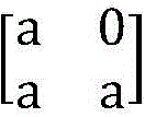
Polar kernel G may be included in submatrix a N And 0 element. Wherein, polar nucleus G N May be distributed in the lower left corner of the sub-matrix a and may be distributed in a triangle. polar nucleus G N The sides of the triangle may be formed. To be provided withNext, a polar kernel matrix having a submatrix a of 2 × 2 size and a polar kernel matrix having a submatrix a of 4 × 4 size will be described as examples. It should be noted that the sub-matrix a may also be 8 × 8, 16 × 16 or 2 m *2 m A polar kernel matrix of size. Optionally, the sub-matrix a may also be polar core G N 。
Referring to fig. 6A, the submatrix a may be a2 × 2 polar kernel matrix. The sub-matrix a may be
Referring to fig. 6B, the submatrix a may be a 4 × 4 polar kernel matrix. The sub-matrix a may be
Hereinafter, a description will be given of the first generation matrix in the embodiment of the present application, and the first generation matrix can be classified into the following three types according to different coupling methods.
The first method comprises the following steps: and (4) triangular coupling.
Here, triangular coupling may be understood as a triangular distribution of the submatrices a in the first generation matrix. It should be understood that the sub-matrix a may fill the triangle or may also constitute the sides of the triangle. In the embodiment of the present application, the triangle a is used to fill the triangle.
Case 1: the first generation matrix is an upper triangular matrix.
In order to support 1-pass decoding starting from the first sub-block, the first sub-block needs to be able to decode independently and not be able to overlap with other sub-block codewords. The coupled polar matrix needs to be written in an upper triangular form as shown in fig. 7A. In fig. 7A, the first encoding vector includes 8 sub-blocks. Each sub-block may contain a plurality of information bits and a plurality of freeze bits.
The sending device may sequentially fill in information bits and freeze bits according to the reliability of the sub-channel to obtain a plurality of M-length information vectors ui. Wherein an M-long information vector ui can be considered as a second sub-block. Second, the transmitting device may outer code the vector u, which has a total length of T × N, resulting in an outer code word vector v, which has a total length of T × N. The v-vector is then multiplied by the coupling polar matrix in the binary domain.
Optionally, the above encoding process may also be decomposed into outer code encoding, sub-block inner encoding and inter-sub-block coupling encoding. The sending device may perform outer code encoding on the subblock ui to obtain an outer code subblock block vi. The sending equipment then transmits the outer code sub code block vi and the polar core G N Multiplying to obtain the sub-codeword ci. The sending device may superimpose each sub-codeword ci in a coupling manner to obtain a final codeword ci' of the coupling code. Wherein the coupling mode can be as shown in fig. 7A. Specifically, c1 '═ c1, c 2' ═ c1+ c2, c3 '═ c1+ c2+ c3, c 4' ═ c1+ c2+ c3+ c4, c5 '═ c1+ c2+ c3+ c4+ c5, c 6' ═ c1+ c2+ c3+ c4+ c5+ c6, c7 '═ c1+ c2+ c3+ c4+ c5+ c6+ c7, c 8' ═ c1+ c2+ c3+ c4+ c5+ c6+ c7+ c 8.
Case 2: the first generation matrix is a lower triangular matrix.
Since soft decoupling of likelihood ratios (LLRs) is required, processing starts first with the last sub-code block, and the first generator matrix needs to be written in a lower triangular form, as shown in fig. 7B. The first coding vector includes 8 sub-blocks as an example in fig. 7B. Each sub-block may contain a plurality of information bits and a plurality of freeze bits.
The sending device may fill in information bits and freeze bits in sequence according to the reliability of the sub-channel to obtain the M-long information vector u. Wherein an M-long information vector ui can be considered as a second sub-block. Second, the transmitting device may outer code the vector u, which has a total length of T × N, resulting in an outer code word vector v, which has a total length of T × N. The v-vector is then multiplied by the coupling polar matrix in the binary domain.
Alternatively, the above encoding process can be decomposed into outer code encoding, sub-block inner encoding and inter-sub-block coupling encoding. The sending device may perform outer code encoding on the subblock ui to obtain an outer code subblock block vi. The sending device then uses the outer code sub-code block vi and the polar core G N Multiplying to obtain the sub-codeword ci. The transmitting device can couple each sub-codeword ci with the sub-codeword ciAnd superposing to obtain the code word ci' of the final coupling code. Wherein the coupling manner can be as shown in fig. 7B. Specifically, c1 '═ c1+ c2+ c3+ c4+ c5+ c6+ c7+ c8, c 2' ═ c2+ c3+ c4+ c5+ c6+ c7+ c8, c3 '═ c3+ c4+ c5+ c6+ c7+ c8, c 4' ═ c4+ c5+ c6+ c7+ c8, c5 '═ c5+ c6+ c7+ c8, c 6' ═ 6+ c7+ c8, c7 '═ c7+ c8, and c 8' ═ c 8.
Based on the above case 1 and case 2, the sending device may encode the vector to be encoded based on the first generation matrix to obtain the codeword. In the code word obtained by the sending device through the encoding of the first generating matrix, coupling exists among a plurality of sub-blocks, so that higher coupling code encoding gain can be obtained, and the encoding performance can be improved.
In one possible implementation, when obtaining the first vector to be encoded, the transmitting apparatus may first determine the number of second sub-blocks included in the first vector to be encoded. The transmitting device may determine a code rate for each of the second sub-blocks based on the total code rate of the codeword and the number of the second sub-blocks. It should be understood that the code rates of the different second sub-blocks may be different. The transmitting device may determine the first vector to be encoded based on the code rate of each of the second sub-blocks and the number of second sub-blocks included in the first vector to be encoded.
In one example, the transmitting device may determine the code rate of each second sub-block according to a relationship between a pre-stored total code rate and the number of second sub-blocks included in the first vector to be encoded and the code rate of each second sub-block. For example, a code with a total code length N of 1024 may be divided into 2 groups, each group is divided into 4 second sub-blocks, the code length of each second sub-block is 128, the second sub-blocks are only triangularly coupled in the group, and the second sub-blocks between the groups have no coupling relationship. When the total code rate is 1/2, the total information bit number is 512, and the information bit number of each group is 512/2 ═ 256. Because each group has 4 second sub-blocks and polarization exists between the second sub-blocks, the information bit number of each second sub-block is different, and the information bit numbers of the 1 st, 2 nd, 3 rd and 4 th second sub-blocks can be respectively determined to be 33,50,54 and 119 according to the relationship between the total pre-stored code rate, the number of the second sub-blocks contained in the first vector to be coded and the code rate of each second sub-block.
Optionally, the code rates of two adjacent second sub-blocks in the first vector to be encoded may also be the same, and the first vector to be encoded includes at least two different code rates. The transmitting device may determine the code rate of each second sub-block according to the number of second sub-blocks included in the first vector to be encoded and the total code rate.
According to the above example, the relationship between the total code rate, the number of second sub-blocks included in the first vector to be encoded, and the code rate of each second sub-block may be determined by the total code length, the total information length, the total code rate, the number of second sub-blocks, the number of packets, the number of second sub-blocks in each group, and the information length of each second sub-block. See in particular tables 1-9 below.
TABLE 1
TABLE 2
TABLE 3
TABLE 4
TABLE 5
TABLE 6
TABLE 7
TABLE 8
TABLE 9
Based on the grouping of the information bits to be coded, the code rate matching and the constructed first generation matrix, the coding mode of the embodiment of the application has a gain of 0.3dB to 1dB compared with the non-coupled code.
Fig. 8A is a diagram of simulation effects of different encoding methods. In FIG. 8A, the diagram a adopts SC decoding method, and the diagram b adopts SCL decoding method. In the diagram a, the horizontal axis represents signal to noise ratio (SNR) and the vertical axis represents Block Error Rate (BLER). The diagram is represented in the form of EsN0 logarithm of the power ratio between the transmission symbol and the noise, and the unit is dB. Therefore, under the condition of the same signal-to-noise ratio, the error rate of the long code is the lowest, the error rate of the coding mode of the embodiment of the application is slightly higher than that of the long code, and the error rate of the short code is the highest. However, since the complexity of the long code is high, the encoding method provided in the embodiment of the present application can reduce the complexity and increase the gain of encoding. In fig. 8A, the total code length N is 512, and the total information length K is 64. Compared with SC decoding and SCL decoding, SCL decoding can further reduce the error rate. In the encoding method provided by the embodiment of the application, when decoding is performed through the SCL, the error rate is lower than that of the long code and the short code.
Fig. 8B is a diagram of simulation effect of different encoding modes. In FIG. 8B, the diagram a adopts SC decoding method, and the diagram B adopts SCL decoding method. For example, in the diagram a, the horizontal axis represents signal to noise ratio (SNR) and the vertical axis represents Block Error Rate (BLER). Here, EsN0 is expressed in the form of logarithm of the power ratio of the transmission symbol to the noise, and is expressed in units of dB. Therefore, under the condition of the same signal-to-noise ratio, the error rate of the long code is the lowest, the error rate of the coding mode of the embodiment of the application is slightly higher than that of the long code, and the error rate of the short code is the highest. However, since the complexity of the long code is higher, the coding method provided by the embodiment of the present application can reduce the complexity and also improve the coding gain. In fig. 8B, total code length N is 1024, and total information length K is 128. Compared with SC decoding and SCL decoding, the error rate of SCL decoding is higher than that of SC decoding.
As can be seen from fig. 8A and 8B, under the condition of the same code rate, the bit error rate of the delta-coupled matrix coding method provided in the embodiment of the present application is significantly lower than that of the short code, but the bit error rate is not much different from that of the long code, but the complexity is lower than that of the long code.
In the triangle coupling 1-pass matrix, because only hard bit decoupling is used, but LLR decoupling is not used, the reliability of input LLR of each sub-block is the same, and the polar code structure of the sub-blocks is not different from that of the common polar code.
In the delta-coupled 2-pass matrix, the reliability of each sub-code block is different, so the construction method is different from that of the 1-pass. Firstly, the integral input reliability of the sub-blocks is calculated to obtain the code rate of each sub-block. Equivalently, the number of information bits per sub-block can be obtained. Secondly, the reliability of each subchannel in the subblocks is calculated, and the part is the same as the construction method of the original Polar code.
And the second method comprises the following steps: adjacent coupling.
Wherein the generation matrix of adjacent couplings may contain K first sub-blocks. The K first sub-blocks are positioned on the main diagonal line of the first generating matrix, and the adjacent first sub-blocks are partially overlapped. Where K is greater than or equal to 2. Wherein the first sub-block may be
Or
Hereinafter, different generation matrices for adjacent coupling will be described according to the situation of the first sub-block.
Case 1: the first sub-block is
Referring to fig. 9A, a description will be given of a first sub-block in the embodiment of the present application. Fig. 9A shows a 4 × 4 generator matrix, which includes sub-matrix a and 0 elements. As shown in fig. 9A, the generator matrix includes 3 first sub-blocks. The 3 first sub-blocks are located on a main diagonal of the first generation matrix.
In order to support 1-pass decoding starting from the first sub-block, the first sub-block needs to be independently decodable without overlapping with other sub-block codewords. The coupled Polar matrix needs to be written in an upper triangular form as shown in FIG. 9B. In fig. 9B, the first generating matrix includes 7 first sub-blocks as an example. The first vector to be encoded includes 8 small blocks and 7 second sub-blocks.
The transmitting device may sequentially fill in information bits and freeze bits according to the reliability of the sub-channel to obtain a plurality of M-length information vectors ui. Second, the transmitting device may outer code the vector u, which has a total length of T × N, resulting in an outer code word vector v, which has a total length of T × N. The v-vector is then multiplied by the coupling polar matrix in the binary domain. In fig. 9B, the second sub-block 1 may be u1+ u2, the second sub-block 2 may be u2+ u3, the second sub-block 3 may be u3+ u4, the second sub-block 4 may be u4+ u5, the second sub-block 5 may be u5+ u6, the second sub-block 6 may be u6+ u7, and the second sub-block 7 may be u7+ u 8.
Optionally, the above encoding process may also be decomposed into outer code encoding, sub-block inner encoding and inter-sub-block coupling encoding. The sending device may perform outer code encoding on the subblock ui to obtain an outer code subblock block vi. The sending device then uses the outer code sub-code block vi and the polar core G N Multiplying to obtain the sub-codeword ci. The sending device may superimpose the sub-codewords ci according to the coupling manner for each sub-codeword ci to obtain a final codeword ci' of the coupling code. Wherein the coupling manner can be as shown in fig. 9B. Specifically, c1 '═ c1, c 2' ═ c1+ c2, c3 '═ c2+ c3, c 4' ═ c3+ c4, c5 '═ c4+ c5, c 6' ═ c5+ c6, c7 '═ c6+ c7, and c 8' ═ c7+ c 8.
Case 2: the first sub-block is
Referring to fig. 10A, a first sub-block in the embodiment of the present application will be described. Fig. 10A shows a 4 × 4 generator matrix including sub-matrix a and 0 elements. As shown in fig. 10A, the generator matrix includes 3 first sub-blocks. The 3 first sub-blocks are located on a main diagonal of the first generation matrix.
Since soft decoupling of LLRs is required, processing starts first with the last sub-code block, and the first generator matrix needs to be written in the form of a lower triangle, as shown in fig. 10B. In fig. 10B, the first generation matrix includes 7 first sub-blocks as an example. The first vector to be encoded includes 8 small blocks and 7 second sub-blocks.
The transmitting device may fill in information bits and freeze bits in sequence according to the reliability of the sub-channels to obtain a plurality of M-long information vectors ui. Next, the transmitting device may perform outer code encoding on the vector u, where the total length is T × N, to obtain an outer code word vector v with the same total length as T × N. The v-vector is then multiplied by the coupling polar matrix in the binary domain. In fig. 10B, the second sub-block 1 may be u1+ u2, the second sub-block 2 may be u2+ u3, the second sub-block 3 may be u3+ u4, the second sub-block 4 may be u4+ u5, the second sub-block 5 may be u5+ u6, the second sub-block 6 may be u6+ u7, and the second sub-block 7 may be u7+ u 8.
Optionally, the above encoding process may also be decomposed into outer code encoding, sub-block inner encoding and inter-sub-block coupling encoding. The sending device may perform outer code encoding on the sub-block ui to obtain an outer code sub-code block vi. The sending device then uses the outer code sub-code block vi and the polar core G N Multiplying to obtain the sub-codeword ci. The sending device may superimpose the sub-codewords ci according to the coupling manner for each sub-codeword ci to obtain a final codeword ci' of the coupling code. Wherein the coupling manner can be as shown in fig. 10B. Specifically, c1 '═ c1+ c2, c 2' ═ c2+ c3, c3 '═ c3+ c4, c 4' ═ c4+ c5, c5 '═ c5+ c6, c 6' ═ c6+ c7, c7 '═ c7+ c8, and c 8' ═ c 8.
Based on the foregoing cases 1 and 2, in the codeword obtained by the sending device performing encoding through the first generator matrix, there is coupling between two adjacent sub-blocks, so that a coupling code encoding gain can be obtained, and the performance of encoding can be improved.
And the third is that: coupling of tail biting
The tail-biting coupling is determined based on the generator matrix of the adjacent coupling, and can be divided into the following two cases:
case 1, the first generation matrix is in the form of an upper triangle.
Wherein if the first generation matrix is written in the upper triangular form, there is a sub-matrix a located at the lower left corner of the first generation matrix, as shown in fig. 11A. In fig. 11A, the first generation matrix may include 7 first sub-blocks, each of which includes 16 sub-matrices a, and the first generation matrix further includes 1 sub-matrix a located at the lower left corner of the first generation matrix.
The sending device may perform outer code encoding on a plurality of M-length information vectors ui, the total length of which is T × N, to obtain an outer code codeword vector v having the same total length as T × N. The v-vector is then multiplied by the coupling polar matrix in the binary domain. In fig. 11A, the second sub-block 1 may be u1+ u2, the second sub-block 2 may be u2+ u3, the second sub-block 3 may be u3+ u4, the second sub-block 4 may be u4+ u5, the second sub-block 5 may be u5+ u6, the second sub-block 6 may be u6+ u7, and the second sub-block 7 may be u7+ u 8.
Optionally, the above encoding process may also be decomposed into outer code encoding, sub-block inner encoding and inter-sub-block coupling encoding. The sending device may perform outer code encoding on the sub-block ui to obtain an outer code sub-code block vi. The sending device then uses the outer code sub-code block vi and the polar core G N Multiplying to obtain the sub-codeword ci. The sending device may superimpose each sub-codeword ci in a coupling manner to obtain a final codeword ci' of the coupling code. Wherein the coupling manner can be as shown in fig. 11A. Specifically, c1 '═ c1+ c2, c 2' ═ c2+ c3, c3 '═ c3+ c4, c 4' ═ c4+ c5, c5 '═ c5+ c6, c 6' ═ c6+ c7, c7 '═ c7+ c8, and c 8' ═ c8+ c 1.
Case 2, the first generation matrix is in the form of lower triangles.
Wherein if the first generation matrix is written in the lower triangular form, there is a sub-matrix a located in the upper right corner of the first generation matrix, as shown in fig. 11B. In fig. 11B, the first generating matrix may include 7 first sub-blocks, each of which includes 16 sub-matrices a, and the first generating matrix further includes 1 sub-matrix a located at the upper right corner of the first generating matrix.
The sending device may perform outer code encoding on a plurality of M-length information vectors ui, the total length of which is T × N, to obtain an outer code codeword vector v having the same total length as T × N. The v-vector is then multiplied by the coupling polar matrix in the binary domain. In fig. 11B, second sub-block 1 may be u1+ u2, second sub-block 2 may be u2+ u3, second sub-block 3 may be u3+ u4, second sub-block 4 may be u4+ u5, second sub-block 5 may be u5+ u6, second sub-block 6 may be u6+ u7, and second sub-block 7 may be u7+ u 8.
Optionally, the above encoding process may also be decomposed into outer code encoding, sub-block inner encoding and inter-sub-block coupling encoding. The sending device may perform outer code encoding on the sub-block ui to obtain an outer code sub-code block vi. The sending device then uses the outer code sub-code block vi and the polar core G N Multiplying to obtain the sub-codeword ci. The sending device may superimpose each sub-codeword ci in a coupling manner to obtain a final codeword ci' of the coupling code. Wherein the coupling manner can be as shown in fig. 11A. Specifically, c1 ═ c1+ c8, c2 ═ c1+ c2, c3 ═ c2+ c3, and c4 ═ cc3+c4,c5’=c4+c5,c6’=c5+c6,c7’=c6+c7,c8’=c7+c8。
In a possible implementation manner, in the case of performing encoding based on the generation matrices of the proximity coupling and the tail-biting coupling, when the transmitting apparatus obtains the first vector to be encoded, the transmitting apparatus may determine the number of second sub-blocks included in the first vector to be encoded. The transmitting device may determine a code rate for each of the second sub-blocks based on the total code rate of the codeword and the number of second sub-blocks. Wherein, the code rate of each second sub-block may be different. The transmitting device may determine the first vector to be encoded based on the code rate of each second sub-block.
In one example, the transmitting device may determine the code rate of the second sub-block according to a pre-stored relationship between the total code rate and the number of the second sub-blocks and the code rate of each second sub-block. For example, a code with a total code length N of 1024 may be divided into 2 groups, each group is divided into 4 small blocks, and the code length of the small blocks is 128. The sub-blocks are only coupled adjacently in the group, and the sub-blocks between the groups have no coupling relation. When the total code rate is 1/2, the total information bit number is 512, and the information bit number of each group is 512/2 ═ 256. Since each group has 4 small blocks and polarization exists between the small blocks, the information bit number of each small block is different, and according to the code construction method described above, the information bit numbers of the 1 st, 2 nd, 3 th and 4 th small blocks can be determined to be 12,72,80 and 92 respectively. The information bit number of sub-block 1 is 12+ 72-84, the information bit number of sub-block 2 is 72+ 80-152, and the information bit number of sub-block 3 is 80+ 92-172.
Optionally, the code rates of two adjacent second sub-blocks in the first vector to be encoded may also be the same, and the first vector to be encoded includes at least two different code rates. The transmitting device may determine the code rate of each second sub-block according to the number of second sub-blocks included in the first vector to be encoded and the total code rate.
According to the above example, the relationship between the total code rate and the number of the second sub-blocks and the code rate of each second sub-block may be determined by the total code length, the total information length, the total code rate, the number of small blocks, the number of packets, the number of second sub-blocks in each group and the information length of each small block. See in particular tables 1-9 below.
TABLE 10
TABLE 11
TABLE 12
Watch 13
TABLE 14
Watch 15
TABLE 16
TABLE 17
Watch 18
Based on the grouping of the information bits to be coded, the code rate matching and the constructed first generation matrix, the coding mode of the embodiment of the application has a gain of 0.3dB to 1dB compared with the non-coupled code.
In the 1-pass matrix of adjacent coupling or tail-biting coupling, because only hard bit decoupling is used, but LLR decoupling is not used, the input LLR reliability of each sub-block is the same, and the polar code structure of the sub-blocks is not different from that of the common polar code.
In the 2-pass matrix of close-coupled or tail-biting coupling, the reliability of each sub-channel is different, and thus the construction method is different from that of the 1-pass. Firstly, the integral input reliability of the sub-blocks is calculated to obtain the code rate of each sub-block. Equivalently, the number of information bits per sub-block can be obtained. Secondly, the reliability of each subchannel in the subblocks is calculated, and the part is the same as the construction method of the original Polar code.
In one possible implementation, the proximity coupling scheme performs better in high bitrate regions, while the triangular coupling scheme performs better in low bitrate regions. Therefore, it can be determined which coupling scheme is adopted when the code rate is less than or equal to Rth or greater than or equal to Rth by taking Rth as a boundary. For example, when the code rate R < Rth or R ≦ Rth, a triangle coupling scheme may be used, the code rate R ≧ Rth or R > Rth, or a proximity coupling/tail-biting coupling scheme may be used. Herein, Rth can be defined as 1/2, 7/16, 9/16, 3/8 or 5/8 and other intermediate code rates.
Fig. 12A is a diagram of simulation effects of different encoding methods. In FIG. 12A, the diagram a adopts SC decoding method, and the diagram b adopts SCL decoding method. In the diagram a, the horizontal axis represents signal to noise ratio (SNR) and the vertical axis represents Block Error Rate (BLER). Here, EsN0 is expressed in the form of logarithm of the power ratio of the transmission symbol to the noise, and is expressed in units of dB. Therefore, under the condition of the same signal to noise ratio, the error rate of the long code is the lowest, the error rate of the coding mode of the embodiment of the application is slightly higher than that of the long code, and the error rate of the short code is the highest. However, since the complexity of the long code is high, the encoding method provided in the embodiment of the present application can reduce the complexity and increase the gain of encoding. In fig. 12A, the total code length N is 514, and the total information length K is 448. According to the coding mode provided by the embodiment of the application, when decoding is carried out through the SCL, the error rate is not greatly different from that of the long code. Compared with SC decoding and SCL decoding, SCL decoding can further reduce the error rate.
Fig. 12B is a diagram illustrating simulation effects of different encoding methods. In FIG. 12B, the diagram a adopts SC decoding method, and the diagram B adopts SCL decoding method. In the diagram a, the horizontal axis represents signal to noise ratio (SNR) and the vertical axis represents Block Error Rate (BLER). The diagram is represented in the form of EsN0 logarithm of the power ratio between the transmission symbol and the noise, and the unit is dB. Therefore, under the condition of the same signal-to-noise ratio, the error rate of the long code is the lowest, the error rate of the coding mode of the embodiment of the application is slightly higher than that of the long code, and the error rate of the short code is the highest. However, since the complexity of the long code is high, the encoding method provided in the embodiment of the present application can reduce the complexity and increase the gain of encoding. In fig. 12A, the total code length N is 1024, and the total information length K is 896. Compared with SC decoding and SCL decoding, SCL decoding can further reduce the error rate.
As can be seen from fig. 12A and 12B, under the condition of the same code rate, the bit error rate of the delta-coupled matrix coding method provided in the embodiment of the present application is significantly lower than that of the short code, but the bit error rate is not much different from that of the long code, but the complexity is lower than that of the long code.
Step 304, the sending device sends the encoded code word to the receiving device, and the corresponding receiving device receives the code word from the sending device.
Step 305, the receiving device decodes the code word.
When the receiving device decodes the code word, the code word can be decoded based on the first generation matrix. Optionally, the receiving device may decode the code word by using different first generation matrices according to different encoding modes. Here, depending on the encoding method, decoding will be described in the following 4 cases.
Case 1, 1-pass decoding of the triangular coupling matrix.
The characteristics of the 1-pass decoding of the triangular coupling matrix can include the following two characteristics:
1. LLR transfer within the total transmission length range is not required, and only part of LLRs need to be copied between adjacent sub-blocks.
2. Window decoding supporting lower latency: decoding is performed while receiving LLR, and complexity is lower.
When the triangular coupling matrix is in hard decoupling, the decoding results of all the previous sub-blocks need to be utilized to write the LLR to be decoded of the current sub-block. If the exclusive or value of the ith bit of all the previous sub-blocks is 0, the ith channel receiving LLR of the current sub-block is directly sent to the current sub-block decoder. And if the exclusive-or value of the ith bit of all the previous sub-blocks is 1, inverting or multiplying the symbol of the ith channel receiving LLR of the current sub-block by-1 and then sending the result to the current sub-block decoder.
In one example, the decoding approach may be as shown in fig. 13A. Wherein, firstly, the hard decoupling of the code words between the sub-blocks is carried out. It should be understood that the first sub-block need not be hard decoupled from the codeword. Wherein the hard decoupling of the code words among the sub-blocks means that: and writing the decoding result of the previous sub-block into the LLR to be decoded of the current sub-block.
Assuming that the current sub-block is the t-th sub-block, the exclusive-or value of the ith bit of all the previous sub-blocks is xt-1, i is c1, i + c2, i + … + ct-1, i, the ith value of the channel output LLR of the current sub-block is lt, i, the ith LLR value sent to the current sub-block decoder is lt, i
And repeating the steps until the last sub-block is translated.
Case 2, 2-pass decoding of the triangular coupling matrix.
The characteristics of the 1-pass decoding of the triangular coupling matrix can include the following two characteristics:
1. a backward-pass of LLRs over the total transmission length is required, followed by a forward-pass of decoding results, sub-block by sub-block.
2. Polarization phenomena can be formed among the sub-blocks, and partial long code gains can be obtained as far as possible.
But since the triangular coupling matrix is different from the adjacent coupling matrix, the decoding method is also different. The following figures represent:
in one example, the decoding approach may be as shown in fig. 13B. Wherein, firstly, forward transmission of soft decoupling of code words between sub-blocks is carried out. It should be understood that the last sub-block does not require codeword soft decoupling. Assuming that the ith codeword bit of the last sub-block is ct-1, i, the ith value of the forward decoupling LLR of the last sub-block is lt-1, i, and the ith value of the channel reception LLR of the current sub-block is l't, i, the ith value of the forward decoupling LLR of the current sub-block is lt, i ═ g (ct-1, i, lt-1, i, l't, i). Assuming that the ith value of the forward decoupling LLR of the current sub-block is lt, i ═ g (ct-1, i, lt-1, i, l't, i), and the ith value of the channel reception LLR of the next sub-block is l't +1, i, the ith value of the reverse decoupling LLR of the sub-block is lt, i ═ f (lt, i, l't +1, i). And sending the reverse decoupling LLR of the current sub-block into the current sub-block decoder, and repeating the steps until the last sub-block is decoded.
Case 3, 1-pass decoding of the proximity coupling and tail-biting coupling matrices.
The 1-pass decoding of the proximity coupling and tail-biting coupling matrixes can comprise the following two characteristics:
1. LLR transfer within the total transmission length range is not required, and only partial LLRs need to be copied between adjacent sub-blocks.
2. Window decoding supporting lower latency: decoding is performed while receiving LLR, and complexity is lower.
In one example, the decoding approach may be as shown in fig. 13A. Wherein, firstly, the hard decoupling of code words between sub-blocks is carried out. It should be understood that the first sub-block does not require soft codeword decoupling. Assuming that the ith bit of the previous sub-block is ci and the ith value of the channel output LLR of the current sub-block is li, the ith value sent to the decoder of the current sub-block is li
And repeating the steps until the last sub-block is translated. If the ith bit of the previous sub-block is 0, the ith channel receiving LLR of the current sub-block is directly sent to the current sub-code decoder. And if the ith bit of the previous sub-block is 1, inverting or multiplying the symbol of the ith channel received LLR of the current sub-block by-1 and then sending the result to the current sub-code decoder.
Case 4, 2-pass decoding of proximity-coupled and tail-biting coupling matrices
The 2-pass decoding of the proximity coupling matrix and the tail-biting coupling matrix can comprise the following two characteristics:
2. a backward-pass of LLRs over the total transmission length is required, followed by a forward-pass of decoding results, sub-block by sub-block.
2. Polarization phenomena can be formed among the sub-blocks, and partial long code gains can be obtained as far as possible.
In one example, the decoding approach may be as shown in fig. 13B. Wherein, firstly, the reverse transfer of the soft decoupling of the code words between the sub-blocks is carried out. It should be understood that there is one sub-block at most that does not require soft decoupling of the codewords. Assuming that the ith value of the channel-received LLR of the current sub-block is l't, i, and the ith value of the channel-received LLR of the next sub-block is l't +1, i, the ith value of the reverse decoupling LLR of the sub-block is lt, i ═ f (l't, i, l't +1, i). Assuming that the ith codeword bit of the last sub-block is ct-1, i, the ith value of the channel receiving LLR of the last sub-block is l't-1, i, and the ith value of the reverse decoupling LLR of the current sub-block is lt, i, the ith value of the forward decoupling LLR is lt, i ═ g (ct-1, i, l't-1, i, lt, i). And sending the forward decoupling LLR of the current sub-block into a current sub-block decoder, and repeating the steps until the last sub-block is decoded.
In a possible implementation manner, the sending device and the receiving device may respectively determine the type of the outer code, the polynomial of the outer code, the number of outer code groups, the degree of coupling, the number of coupling groups, the coupling relationship, the selection of the coupling matrix, and other coupling related parameters. Wherein the coupling related parameters may be determined by parameters of the scene and the codeword, etc.
Optionally, the transmitting device or the receiving device may determine a specific coupling scheme according to parameters such as a code length or an application scenario, where the specific coupling scheme includes coupling related parameters such as the outer code, the number of packets, the coupling degree, and the coupling manner shown in the foregoing. The sending device may negotiate the coupling related parameter with the receiving device through signaling, or the sending device may indicate the coupling related parameter to the receiving device, or the receiving device may indicate the coupling related parameter to the sending device. Optionally, the coupling related parameter may also be specified by a communication protocol, and the application is not particularly limited. Then the transmitting and receiving parties carry out coding and decoding communication according to an appointed mode.
In one example, the transmitting device and the receiving device may negotiate or indicate the coupling-related parameters through Radio Resource Control (RRC) messages. Optionally, a part of fields may be added to the RRC message to carry the coding configuration information. The encoding configuration information may include the plurality of coupling related parameters.
In another example, the transmitting apparatus or the receiving apparatus may indicate the coupling related parameter through Downlink Control Information (DCI). Alternatively, the format of the DCI may be as shown in table 19 below.
Watch 19
In one possible implementation, the bits to be encoded may be divided into groups, each group containing a specified number of Code Blocks (CBs). There may be a coupling relationship between the code blocks in each group, as shown in fig. 14. For the coupling relationship among the code blocks, reference may be made to the relevant description in the above three encoding modes, and fig. 14 shows only one coupling mode by way of example.
In one example, if the number of bits to be coded B is greater than a certain thresholdValue K cb Then, the B bits to be coded are segmented (segmentation), and the CRC belonging to the CB is added to each segment of information bits. Assuming CRC is L length, L>0. The number of bits to be coded after adding the CRC bits is B', and the flow is as follows:
If B<=K cb
CRC length of 0
The number of CBs: c1
B’=B
And (3) encoding: b' information bits → N codeword bits
Else
CRC length L
b' ═ B + CB number × L
For r=0:C-1
Sub-block intra coding the r-th CB: c. C r =CB_encode(u r )
End for
For r=0:C-1
Inter-sub-block (coupling) coding the r-th CB: c' r =Couple_encode(c r ,c r1 ,c r2 ,…c rl )
(wherein c is r1 ,c r2 ,…c rl For sub-blocks coupled to the r-th CB)
End forc'2=couple_encode(c 2 ,c 1 )=c 2 +c 1
End if
After segmentation, C segment information vector u 0 ,u 1 ,…,u C-1 After respective encoding, the obtained code word vector is c 0 ,c 1 ,…,c C-1 Wherein the codeword bit of the r-th CB is c r =[c r0 ,c r1 ,…,c r(Nr-1) ]And Nr is the number of bits of the subblock code word of the r-th CB. And then performing sub-block inter-coding on the C CBs to obtain a codeword vector of C' 0 ,c’ 1 ,…,c’ c-1 Wherein codeword bits of the r-th CB are c' r =[c’ r0 ,c’ r1 ,…,c’ r(Mr-1) ]Where Mr is the number of coupled codeword bits for the r-th CB. Wherein c is r1 ,c r2 ,…c rl For sub-blocks having coupling relation with the r-th CB, the coupling code word of the r-th CB is formed by the r-th CB 1 ,r 1 ,…,r l The sub-block codewords of each CB are generated by coupled coding. R is 1 or more.
In another example, if the number of bits to be coded B is greater than a certain threshold K cb Then the B bits to be coded are segmented (segmentation) and the CRC belonging to the CB is added to each segment of information bits. Assuming CRC is L long, L>0. The number of bits to be coded after adding the CRC bits is B', and the flow is as follows:
If B<=K cb
CRC length of 0
The number of CBs: c1
B’=B
And (3) encoding: b' information bits → N codeword bits
Else
CRC length L
b' ═ B + CB number × L
Code rate (information bit) allocation is performed for C CBs: { K 1 ,K 2 ,…,K C }=Rate_allocation(B’,C)
For r=0:C-1
Sub-block intra coding the r-th CB: c. C r =CB_encode(u r )c' 3 =couple_encode(c 3 ,c 2 ,c 1 )=c 3 +c 2 +c 1
End for
For r=0:C-1
Inter-sub-block (coupling) coding the r-th CB: c' r =Couple_encode(c r ,c r1 ,c r2 ,…c rl )
(wherein c is r1 ,c r2 ,…c rl For sub-blocks coupled to the r-th CB)
End for
End if
After segmentation, code rate (information bit) distribution is firstly carried out on C CBs to obtain that the information bit quantity of each subblock is respectively K 1 ,K 2 ,…,K C Wherein the number of information bits of the r-th CB is K r . Wherein Kr may or may not contain CRC bits. K is 1 +K 2 +…+K C B'. C segment information vector u 0 ,u 1 ,…,u C-1 After respective encoding, the obtained code word vector is c 0 ,c 1 ,…,c C-1 Wherein the codeword bit of the r-th CB is c r =[c r0 ,c r1 ,…,c r(Nr-1) ]And Nr is the number of bits of the subblock code word of the r-th CB. And then performing sub-block inter-coding on the C CBs to obtain a codeword vector of C' 0 ,c’ 1 ,…,c’ c-1 Wherein the codeword bit of the r-th CB is c' r =[c’ r0 ,c’ r1 ,…,c’ r(Mr-1) ]Where Mr is the number of coupled codeword bits for the r-th CB. Wherein c is r1 ,c r2 ,…c rl For sub-blocks having coupling relation with the r-th CB, the coupling code word of the r-th CB is formed by the r-th CB 1 ,r 1 ,…,r l The subblock codewords of each CB are generated through coupled coding.
Based on the same technical concept as the above-described communication method, as shown in fig. 15, an apparatus 1500 is provided. The apparatus 1500 may include a processing unit 1520 and an input-output unit 1510. Optionally, a memory unit 1530 is further included; the processing unit 1520 may be connected to a memory unit 1530 and an input/output unit 1510, respectively, and the memory unit 1530 may also be connected to the input/output unit 1510. Among other things, the processing unit 1520 may be integrated with the memory unit 1530. The input-output unit 1510 may also be referred to as a transceiver, a transceiving device, etc. The processing unit 1520 may also be referred to as a processor, a processing board, a processing module, a processing device, etc. Alternatively, a device used for realizing a receiving function in the input/output unit 1510 may be regarded as a receiving unit, and a device used for realizing a transmitting function in the input/output unit 1510 may be regarded as a transmitting unit, that is, the input/output unit 1510 includes a receiving unit and a transmitting unit. The input/output unit may also be referred to as a transceiver, a transmitting/receiving circuit, or the like. A receiving unit may also be referred to as a receiver, a receiving circuit, or the like. A transmitting unit may also sometimes be referred to as a transmitter, or a transmitting circuit, etc.
It should be understood that the input/output unit 1510 is configured to perform the transmitting operation and the receiving operation of the transmitting device and the receiving device in the above method embodiments, and the processing unit 1520 is configured to perform other operations besides the transceiving operation on the transmitting device and the receiving device in the above method embodiments. For example, in one implementation, the input-output unit 1510 is configured to perform a transmitting operation of the transmitting apparatus and a receiving operation of the receiving apparatus shown in step 304 in fig. 3. And/or the input/output unit 1510 is further configured to perform other transceiving steps of the transmitting device and the receiving device in the embodiment of the present application. A processing unit 1520, configured to perform the processing steps of the sending apparatus shown in steps 301 to 303 and the processing operation of the receiving apparatus shown in step 305 in fig. 3, and/or the processing unit 1520, configured to perform other processing steps of the sending apparatus and the receiving apparatus in the embodiment of the present application.
It should be noted that the encoding apparatus shown in the embodiment of the present application may execute the technical solutions shown in the foregoing method embodiments, and the implementation principle and the beneficial effects thereof are similar, and are not described again here.
The storage unit 1530 for storing a computer program;
illustratively, when the apparatus 1500 is configured to perform the steps performed by the transmitting device, the processing unit 1520 is configured to obtain a first vector to be encoded; the processing unit 1520 is further configured to perform first encoding on the first vector to be encoded to obtain a second vector to be encoded; performing second coding on the second vector to be coded based on the first generating matrix to obtain a coded code word; the input/output unit 1510 is configured to send the encoded codeword. For the first generation matrix, reference may be made to the related description in the method embodiment shown in fig. 3, which is not described herein again.
In one possible implementation, the processing unit 1520 is further configured to: determining the number of second sub-blocks contained in the information bits to be coded; determining the code rate of each second sub-block contained in the information bits to be coded based on the total code rate of the code words and the number of the second sub-blocks; wherein, the code rate of each second sub-block is different; the processing unit 1520, when obtaining the first vector to be encoded, is specifically configured to: determining a first vector to be coded based on the code rate of each second sub-block; the first vector to be encoded contains q second sub-blocks, q being an integer greater than 0.
Illustratively, the apparatus 1500 is configured to perform the steps performed by the receiving device, the input-output unit 1510 is configured to receive the codeword; the code word is encoded based on a first generator matrix. The processing unit 1520 is configured to decode the codeword. For the first generation matrix, reference may be made to the related description in the method embodiment shown in fig. 3, which is not described herein again.
Fig. 16 is a schematic diagram of a hardware structure of a device according to an embodiment of the present disclosure. The apparatus 1600 is configured to implement the functions of the sending device in the method. When the device is used for realizing the function of the sending equipment in the method, the device may be the sending equipment, may also be a chip similar to the function of the sending equipment, or may be a device capable of being used in match with the sending equipment. The device 1600: a processor 1601, and a memory 1602.
A memory 1602 for storing computer programs and also for storing intermediate data;
a processor 1601 is used to execute the computer program stored in the memory to implement the steps of the encoding method. Reference may be made in particular to the description relating to the previous method embodiments.
Alternatively, the memory 1602 may be separate or integrated with the processor 1601. In some embodiments, the memory 1602 may even be located outside the encoding apparatus 1600.
When the memory 1602 is a device separate from the processor 1601, the coding apparatus 1600 may further include a bus 1603 for connecting the memory 1602 and the processor 1601.
Optionally, the apparatus 1600 may further comprise a transmitter. For example, the transmitter is used to transmit the encoded bits.
The apparatus 1600 provided in this embodiment may be a terminal device or a network device, and may be configured to execute the encoding method, which has similar implementation and technical effects, and this embodiment is not described herein again.
Fig. 17 is a schematic diagram of a hardware structure of a device according to an embodiment of the present disclosure. The apparatus 1700 is used to implement the functions of the receiving device in the above method. When the apparatus is used to implement the function of the receiving device in the above method, the apparatus may be the receiving device, or may be a chip similar to the function of the receiving device, or may be an apparatus capable of being used in cooperation with the receiving device. The device 1700: a processor 1701 and a memory 1702.
A memory 1702 for storing computer programs and also for storing intermediate data;
the processor 1701 is configured to execute the computer program stored in the memory to implement the respective steps in the above-described encoding method. Reference may be made in particular to the description relating to the preceding method embodiment.
Alternatively, the memory 1702 may be separate or integrated with the processor 1701. In some embodiments, the memory 1702 may even be located outside the encoding apparatus 1700.
When the memory 1702 is a separate device from the processor 1701, the encoding apparatus 1700 may further include a bus 1703 for connecting the memory 1702 and the processor 1701.
Optionally, the apparatus 1700 may further comprise a receiver. For example, the receiver is used to receive the encoded bits.
The apparatus 1700 provided in this embodiment may be a terminal device or a network device, and may be configured to execute the above encoding method, and its implementation manner and technical effect are similar, and are not described herein again.
Fig. 18 is a schematic structural diagram of an apparatus according to an embodiment of the present application. Referring to fig. 18, the apparatus 1800 may include a communication interface 1801 and logic 1802.
The logic circuit 1802 is configured to obtain a first vector to be encoded; and carrying out first coding on the first vector to be coded to obtain a second vector to be coded. Performing second coding on the second vector to be coded based on the first generation matrix to obtain a coded code word; wherein the first generation matrix comprises at least N +1 sub-matrices a, the N sub-code blocks are located on a main diagonal of the first generation matrix, the first generation matrix is a block-up triangular matrix, or the first generation matrix is a block-down triangular matrix, where a is a size of 2 m *2 m M is a natural number and N is a natural number; the communication interface is used for outputting the code words after the coding is sent.
Alternatively, the communication interface 1801 may have the function of the input-output unit 1510 in the embodiment of fig. 15. The logic circuit 1802 may have the function of the processing unit 1520 in the embodiment of fig. 15.
Alternatively, the logic circuit 1802 may have the function of the processor 1601 in the embodiment of fig. 16. The logic circuit 1802 may also perform other steps in the encoding method.
The apparatus 1800 according to the embodiment of the present application may implement the technical solutions shown in the above method embodiments, and the implementation principles and the advantageous effects thereof are not repeated here.
Fig. 19 is a schematic structural diagram of another apparatus provided in the embodiment of the present application. Referring to fig. 19, the apparatus 1900 may include a communication interface 1901 and a logic circuit 1902.
The communication interface 1901 is configured to input a coded codeword;
the logic circuit 1902 is configured to decode the codeword.
Alternatively, the communication interface 1901 may have the function of the input-output unit 1510 in the embodiment of fig. 15. The logic circuit 1902 may have the functionality of the processing unit 1520 in the embodiment of fig. 15.
Alternatively, the communication interface 1901 may have the function of the receiver in the embodiment of fig. 17. The logic circuit 1902 may have the function of the processor 1701 in the embodiment of fig. 17. The logic circuit 1902 may also perform other steps in the decoding method.
Optionally, the communication interface 1901 may also output the decoding result.
The apparatus 1900 according to the embodiment of the present application can execute the technical solutions shown in the foregoing method embodiments, and its implementation principles and beneficial effects are not described herein again.
As another form of the present embodiment, there is provided a computer-readable storage medium having stored thereon instructions that, when executed, perform the method of the transmitting device and the receiving device in the above method embodiments.
As another form of the present embodiment, there is provided a computer program product containing instructions that, when executed, perform the methods of the transmitting device and the receiving device in the above-described method embodiments.
As another form of the present embodiment, there is provided a communication system that may include the at least one transmitting device and the at least one receiving device.
It should be understood that the Processor mentioned in the embodiments of the present invention may be a Central Processing Unit (CPU), other general purpose Processor, a Digital Signal Processor (DSP), an Application Specific Integrated Circuit (ASIC), an off-the-shelf Programmable Gate Array (FPGA) or other Programmable logic device, a discrete Gate or transistor logic device, a discrete hardware component, and the like. A general purpose processor may be a microprocessor or the processor may be any conventional processor or the like.
It will also be appreciated that the memory referred to in this embodiment of the invention may be either volatile memory or nonvolatile memory, or may include both volatile and nonvolatile memory. The non-volatile Memory may be a Read-Only Memory (ROM), a Programmable ROM (PROM), an Erasable PROM (EPROM), an Electrically Erasable PROM (EEPROM), or a flash Memory. Volatile Memory can be Random Access Memory (RAM), which acts as external cache Memory. By way of example, and not limitation, many forms of RAM are available, such as Static Random Access Memory (SRAM), Dynamic Random Access Memory (DRAM), Synchronous Dynamic Random Access Memory (SDRAM), Double Data Rate Synchronous Dynamic random access memory (DDR SDRAM), Enhanced Synchronous SDRAM (ESDRAM), Synchronous Link DRAM (SLDRAM), and Direct Rambus RAM (DR RAM).
It should be noted that when the processor is a general-purpose processor, a DSP, an ASIC, an FPGA or other programmable logic device, a discrete gate or transistor logic device, or a discrete hardware component, the memory (memory module) is integrated in the processor.
It should be noted that the memory described herein is intended to comprise, without being limited to, these and any other suitable types of memory.
It should be understood that, in the various embodiments of the present application, the sequence numbers of the above-mentioned processes do not mean the execution sequence, and the execution sequence of the processes should be determined by their functions and inherent logic, and should not constitute any limitation to the implementation process of the embodiments of the present invention.
Those of ordinary skill in the art will appreciate that the various illustrative elements and algorithm steps described in connection with the embodiments disclosed herein may be implemented as electronic hardware or combinations of computer software and electronic hardware. Whether such functionality is implemented as hardware or software depends upon the particular application and design constraints imposed on the implementation. Skilled artisans may implement the described functionality in varying ways for each particular application, but such implementation decisions should not be interpreted as causing a departure from the scope of the present application.
It is clear to those skilled in the art that, for convenience and brevity of description, the specific working processes of the above-described systems, apparatuses and units may refer to the corresponding processes in the foregoing method embodiments, and are not described herein again.
In the several embodiments provided in the present application, it should be understood that the disclosed system, apparatus and method may be implemented in other ways. For example, the above-described apparatus embodiments are merely illustrative, and for example, the division of the units is only one logical division, and other divisions may be realized in practice, for example, a plurality of units or components may be combined or integrated into another system, or some features may be omitted, or not executed. In addition, the shown or discussed mutual coupling or direct coupling or communication connection may be an indirect coupling or communication connection through some interfaces, devices or units, and may be in an electrical, mechanical or other form.
The units described as separate parts may or may not be physically separate, and parts displayed as units may or may not be physical units, may be located in one place, or may be distributed on a plurality of network units. Some or all of the units can be selected according to actual needs to achieve the purpose of the solution of the embodiment.
In addition, functional units in the embodiments of the present application may be integrated into one processing unit, or each unit may exist alone physically, or two or more units are integrated into one unit.
The functions, if implemented in the form of software functional units and sold or used as a stand-alone product, may be stored in a computer readable storage medium. Based on such understanding, the technical solution of the present application or portions thereof that substantially contribute to the prior art may be embodied in the form of a software product stored in a storage medium and including instructions for causing a computer device (which may be a personal computer, a server, or a network device) to execute all or part of the steps of the method according to the embodiments of the present application. And the aforementioned storage medium includes: various media capable of storing program codes, such as a usb disk, a removable hard disk, a Read-Only Memory (ROM), a Random Access Memory (RAM), a magnetic disk, or an optical disk.
The above description is only for the specific embodiments of the present application, but the scope of the present application is not limited thereto, and any person skilled in the art can easily think of the changes or substitutions within the technical scope of the present application, and shall be covered by the scope of the present application. Therefore, the protection scope of the present application shall be subject to the protection scope of the claims.