Disclosure of Invention
This object is achieved by a method for operating an electronic shelf label system, wherein the system has a shelf label fastened to a shelf rail, wherein the shelf label is designed to be supplied with energy in a contactless manner, and the shelf rail has a supply device for the contactless supply of energy to the shelf label fastened to the shelf rail, and the shelf rail has at least one loop, wherein the loop is a component of the supply device of the shelf rail and is used for outputting a signal that can be generated by the supply device for the purpose of the supply of energy to a shelf label positioned at the shelf rail corresponding to the loop, wherein the signal is generated by means of the supply device according to the method and is output via the loop, and the respective shelf label positioned in correspondence with the thread loop stores in a rechargeable long-term energy storage the electrical energy transmitted from the supply device to the shelf label by means of the signal and uses the electrical energy for operating it outside the time interval in which the signal is present.
The object is further achieved by an electronic shelf labeling system having a shelf rail and shelf labels fastened thereto, wherein the shelf labels are configured to be supplied with energy in a contactless manner, and wherein each shelf rail has a supply device for the contactless supply of energy to the shelf labels fastened thereto, and each of the shelf rails has at least one loop, wherein the loop is a component of the supply device of the shelf rail and the loop is used to output a signal that can be generated by the supply device for the purpose of the supply of energy to the shelf labels positioned at the shelf rails in correspondence with the loop, wherein the shelf labels have a rechargeable long-term energy store, and wherein the shelf labels are configured to store in the long-term energy store a signal by means of which the shelf labels are stored Energy transmitted from the supply device to the shelf label and for using the energy present in the long-term energy storage for operating the shelf label outside the time interval in which the signal is present.
Contrary to the known measures, the measures according to the invention occur: contact or wired energy supply of shelf labels at the shelf rail is not required at all. This leads to the advantage that the energy supply of the shelf label takes place completely without mechanical contacts and the associated problems. The system can be produced more cost-effectively and can be operated practically maintenance-free with respect to mechanical components, which are avoided, in particular, because of the easy-to-maintain mechanical components.
Furthermore, energy efficiency aspects in the system are also considered with the necessary attention. Whenever a signal is output by the supply device, it is used in the case of shelf labels located along the relevant wire loop for charging the long-term energy storage. This measure ensures that the power required for generating and outputting the signal, which power has to be provided by means of the supply device, in particular its battery, is optimally used even outside the supply device. In this case, it is to be taken into account that such electronic shelf label systems can have a large number of shelf rails. Thus, for example, up to 100,000 such shelf rails may be installed in a larger supermarket. Since each of these rack rails is equipped with a supply device, in particular battery-operated, this means that 100,000 of these supply devices must above all also be supplied with electrical power or energy. If the power output by means of the signal is not to be converted as completely as possible into an energy store on the shelf label side of the received signal, the energy component required by the supply device for the output signal is to be "clouded" in the form of smoke, i.e. wasted, by the radiation of the signal.
On the one hand, the energy required for outputting the signal can be provided by a battery, in particular rechargeable, which is installed in the supply device. In the case of such a construction, unused radiation losses caused by the output signal lead to a shortened battery life and to increased maintenance costs, or in the case of rechargeable batteries to more frequent charging cycles, which in turn shorten the service life of the battery.
However, attention should be paid to the waste of energy even in the case of a configuration in which the supply device is supplied by means of an electrical power source which is connected on its side to a conventional electrical network. Even in this case, without systematic intermediate storage or buffering of the energy transmitted by means of signals on the side of the shelf labels, which is converted to a large number of supply devices, there is a great difference between the energy delivered into the system and the energy actually used in the system for electronic processing. In this case, as mentioned, a significant component of this difference will be allocated to the unwanted radiation of the signal.
The same applies in the sense of meaning to the provision of the supply means by means of a "WiFi supply".
However, another significant advantage also occurs with the storage of the energy transmitted by means of the signal in the rechargeable long-term energy storage of the shelf label. This measure, in other words, allows the shelf label to be activated not only within the time interval during which the signal is present, but also to be operated completely separately from the energy supply which is currently occurring via the signal, even outside the time interval during which the signal is present. This in turn forms the basis for a wide variety of new construction and use possibilities for shelf labels which are no longer limited or restricted to signals which are usually present for energy-saving reasons as little as possible, as will be discussed in more detail below.
According to a preferred embodiment, the long-term energy store can be realized by a so-called "supercapacitor" (abbreviated to "supercapacitor" (also referred to as "ultracapacitor"). Of course, rechargeable batteries or accumulators may also be used. The advantages of the mentioned supercapacitor however lie in the following fact. Ultracapacitors (also called ultracapacitors) are high-power capacitors that have a much higher capacitance value than in the case of other capacitors, yet have a lower voltage limit, and eliminate the gap between the electrolytic capacitor and the rechargeable battery. The ultracapacitors typically store 10 to 100 times as much energy per volume unit or mass unit of the electrolytic capacitor, can accept and output charge much faster than batteries, and tolerate much more charge and discharge cycles than rechargeable batteries. In the context of the present application, the signals may occur as little as possible for the energy saving considerations mentioned and may then also be present during the shortest possible time intervals. However, such a relatively short signal occurrence can also be optimally used for a fast and in particular sufficient energy storage for later operation outside the time interval in which the signal is present, by means of the supercapacitor.
Despite the fact that small configurations are used when integrating supercapacitors into shelf labels, it should be mentioned here by way of example that supercapacitors and ultracapacitors are commercially available at the time of the present application, for example from a large number of companies, such as AVX, celergy, Elna, Ioxus, Maxwell, Nichicon, Panasonic, PowerStor.
It should also be mentioned at this point that "battery operation" of the supply device is likewise possible by means of the supercapacitors installed there.
Further particularly advantageous embodiments and further developments of the invention emerge from the dependent claims and the following description. The features of one claim category may be further developed in accordance with the features of other claim categories, so that effects and advantages which are listed in connection with one claim category also exist for other claim categories.
In order to use the signal optimally, according to a further aspect, in addition to the energy supply of one or more shelf labels fastened to the shelf rail, communication with one or more selected shelf labels can also be established by means of the signal-building supply device, and each shelf label, when storing the signal, checks if the signal is evaluated: whether the shelf label is selected for communication with a supply device. In addition to the overall energy supply of all shelf tags fastened at the shelf rail along the loop of wire, this enables selective addressing or selective communication establishment with a single shelf tag or a group of shelf tags arranged along the loop of wire.
It is advantageous here if, when a signal is present, each shelf label first establishes its power supply by means of the signal and thereafter checks whether the shelf label is selected for communication with the supply device. Thereby ensuring that the energy stored in the long-term energy storage is exclusively used only when the shelf label is operated outside the time interval in which the signal is present. At the same time, the energy provided by means of the signal is used for directly supplying the shelf label for communication purposes.
In order to optimize the energy yield when storing the energy transmittable by means of the signal, each shelf label, if it is determined that it is not selected for communication with the provision device, reduces its activity to: it is advantageous to use the signal for storing electrical energy during the entire remaining time interval in which the signal is present until the long-term energy storage is charged as completely as possible. For this purpose, the electronics of the shelf label may be constructed such that parts of the electronics, in particular those used for communication purposes and which do not need to be used directly for storing energy during the entire remaining time interval of the presence signal, for example the digital device, are switched off, are currentless or at least are switched into a state with a very low energy consumption.
The electronics of the shelf label can also be designed such that the process of energy storage in the presence of the signal is independent of whether the respective shelf label should take part in the communication with the supply device.
Such electronic shelf labels may provide the most diverse functionality or fulfill the most diverse functions by means of their electronic devices or components. For example, the shelf label may have been configured or, correspondingly, configured for capturing an environmental parameter, such as for capturing temperature or humidity, or as an input element for receiving an input interaction by a user (e.g. capturing a fingerprint or a key operation), or as a display medium for presenting information to the user, i.e. as a shelf label display. There may also be sensors by means of which the distance to an object on the underside of the shelf or in front of the shelf can be determined, such as so-called "time-of-flight" sensors. It may also comprise a camera by means of which a digital image of the product or its EAN code can be generated, which can then be used for registering the product or for establishing a logical association between the product and the associated shelf label. However, it is also possible to use a camera to detect or identify the direction of movement of a person or the movement of his hands in front of the shelf. Identification of the person, such as an identity check and thus opening of the right to the service person, can thus also be carried out. On the basis of this, the real label can, for example, display information or provide interaction possibilities which are only envisaged for the service person or in particular for a specific category of service person (goods regulator, supervisor, etc.).
Thus, at least one shelf label of the system can have at least one electrical consumer (sensor, camera, input element, etc.) which causes an electrical power consumption outside the time interval of the presence signal, wherein according to the method each shelf label having such an electrical consumer compensates the power consumption of the electrical consumer outside the time interval of the presence signal by means of the electrical energy stored in the long-term energy storage.
The one or more consumers are therefore additional components which are provided in addition to those of the shelf label which are necessary for the contactless energy and communication supply and, if appropriate, for displaying information with the shelf label configured as a shelf label display. However, the display unit required for this purpose can also be configured as an electrical consumer and can therefore be supplied by means of a long-term energy store.
The consumer can also be supplied with energy during the presence signal by means of the energy stored in the long-term energy store.
It is particularly advantageous if the respective electrical consumer, during its activity causing the electrical power consumption, processes data outside the time interval in which the signal is present, which data has been previously transmitted from the supply device to the shelf label with the electrical consumer during the communication between the supply device and the shelf label and stored there. This is the case, for example, if biometric data corresponding to the service person have been transmitted previously from the provision device onto the real tag and are then used to identify the person (e.g. the service person) by means of the camera at a later point in time when the signal is no longer present. Thereby, the image content of the display unit of the shelf label can also be changed at every arbitrary point in time outside the time interval in which the signal is present, with full use of the image data previously obtained from the supply device.
Furthermore, it has proven to be advantageous if the respective electrical consumer generates data and stores the data outside the time interval of the presence signal during its activity causing the consumption of electrical power, and thereafter transmits said data from the shelf label to the supply device during the communication with the supply device, i.e. within the time interval of the presence signal. Such a scenario is present, for example, if, in addition to the presence signal, a temperature profile is recorded by means of an electrical consumer, such as a temperature sensor, or a change or removal or replenishment of an object on the shelf floor is detected, for example by means of a time-of-flight sensor, or a user input is captured, for example by means of an input element, or the like. In all these cases, the relevant consumer generates data which, when the signal is present, is transmitted at a later point in time to the supply device for further processing. For this purpose, the respective consumer has a memory unit which is accessible via a data bus from the electronic device of the shelf label provided for communication with the supply device in the presence of the signal. It would also be possible to provide a central memory unit (for example an EEPROM) in which data can be centrally stored by the consumer and from there also be centrally called up by means of the mentioned electronics provided for communication.
The shelf labels are furthermore configured such that they can be placed at a specific shelf rail. The shelf label therefore has fastening elements which are configured substantially complementary to those of the shelf rail in order to be connected in force-transmitting manner to the shelf rail. The realization is preferably rail-like, so that the shelf labels can be freely selectively positioned along the shelf rail and, if necessary, also freely movable along the shelf rail. Positioned there, the shelf labels are supplied with energy in a contactless manner as described in detail below.
The shelf label may have a proprietary interface for energy transfer, which can only be used for this purpose. However, the shelf label preferably has a standardized energy transmission interface, which can be constructed, for example, according to the RFID standard (RFID stands for Radio Frequency Identification and applicable standards are, for example, ISO/IEC 18000 and the like). However, the shelf label particularly preferably has a first NFC interface for the contactless energy supply of the shelf label by means of a (radio) signal (NFC signal). The advantage then arises that the NFC interface can be used not only for local energy transmission at the rack or at the rack rail, but also directly there for two-way contactless communication. In particular, problems in the radio service caused by other radio systems in stores or sales places for goods are thereby avoided, since these other radio systems are usually located away from the shelf on which the shelf label is installed and therefore have little to no influence on the local energy transfer and on the communication between communication partners located close to one another directly at the shelf rail. Here, NFC stands for near field communication, and applicable standards are, for example, ISO/IEC 13157, 16353, 22536, 28361, and the like.
The shelf label, when configured as a shelf label display, may have a display unit that saves energy, such as an LCD display. However, especially the applied technology is based on electronic ink technology or electronic paper technology. Such display units therefore have a reflective screen, which is also referred to in jargon as electronic paper display, abbreviated EPD, and which is implemented by means of "electronic paper" (abbreviated "E-paper", also in english "E-paper" or "E-ink"). These terms basically represent the principle of electrophoretic displays, in which, for example, positively charged white particles and negatively charged black particles are contained in a transparent viscous polymer. By applying a voltage to the electrodes for a short time, either the black particles are placed before the white particles in the viewing direction, or vice versa, wherein a medium made of particles and polymer is arranged between the electrodes. This arrangement is then maintained for a relatively long time (e.g. several weeks) without further energy delivery. If the display is segmented accordingly, for example letters, numbers or images with a relatively high resolution can be implemented in order to display the information. However, such a reflective screen may also be realized by means of other techniques, which are known for example by the term "electrowetting" or "MEMS". As mentioned, the screen can be configured, for example, for black-and-white reproduction, grayscale gradient reproduction, black-and-white-red reproduction or black-and-white-yellow reproduction. And should also include future developments that enable full color or multi-color reproduction together. Such screens are entirely generally reflective, i.e. passive, screens that do not emit light themselves, wherein the (relatively static) information reproduction is based on: light (ambient light) generated by an external (artificial or natural) light source is incident on the screen and is reflected therefrom to the viewer.
The display unit is supplied with energy on the one hand and with data on the other hand by means of the first NFC interface, which data may represent commands or image content for controlling the display unit. The data can therefore also be transmitted via the NFC interfaces during the energy supply via these NFC interfaces, and the data is processed by the display unit in such a way that the image content of the screen of the display unit changes. After the change of the image content is finished, corresponding state information representing the successful change of the image content can also be output by the display unit through the NFC interface. After the change of the image content has ended, and if necessary also after the output of the status information, the supply of energy via the first NFC interface by the signal can be ended, whereby the image content of the screen remains unchanged until the next desired change.
The first NFC interface also has the previously mentioned electronics, in this case in particular a microcontroller unit, which can exchange data with the consumer via a data bus.
In addition to the NFC interface and its digital level, a central microcontroller unit can also be provided in the shelf label, which central microcontroller unit coordinates (controls) the functionality and the processes in the shelf label, but in particular also controls the energy management in the shelf label.
The use of the mentioned technology in particular allows the realization of shelf labels, in particular configured as shelf label displays, without their own batteries or accumulators, which are relatively expensive and require maintenance or replacement over time.
If necessary, a first capacitor, a so-called smoothing capacitor, is used in the shelf label, which smoothing capacitor is usually provided in the case of a voltage supply device (here in the specific case a so-called contactless power transmission unit) for short-term, temporary smoothing or stabilization of the internal supply voltage.
The shelf label can also have one or more second capacitors, so-called auxiliary capacitors, which are usually arranged in a distributed manner in the electronic device in order to locally support the supply voltage in its environment.
The shelf label is therefore designed in such a way that the electronic device of the shelf label for communication with full utilization of the first NFC interface, if necessary also for updating the screen content, is always active only when the shelf label is supplied by a signal by means of an external electronic supply device.
The smoothing capacitor and the auxiliary capacitor allow the first NFC interface to be operated only very briefly, over time, when the signal is cancelled, until the supply voltage established via the NFC interface itself collapses. Since this point in time, only the electrical energy stored in the long-term energy store is available to the consumers of the rack tags, with which operation can be maintained for several hours until the long-term energy store has to be charged again by means of a signal (e.g. an NFC signal).
The housing of the shelf label can be completely and permanently encapsulated, since it is no longer necessary to replace the battery or accumulator, so that the housing is opened only for recycling purposes (for example with special tools).
NFC functionality, such as standardized NFC communication together with standardized energy supply during NFC communication, can be realized by means of commercially available NFC modules (e.g. for realizing NFC tags). Together with the discussed display capabilities, it is thus possible to realize shelf labels that are reduced to a small number of absolutely required electronic components and are therefore also extremely beneficial in terms of both power properties.
The screen updating of the energy-saving display unit and the status reporting thereof are not done directly by the shelf label display in communication with the access point (as is the case in the already existing systems), but rather by an intermediately connected supply device which acts as a relay station and is in contact with the access point on its side via a suitable (and substantially freely selectable) communication method, which is discussed in more detail below.
If a function beyond the pure display capability is required, the shelf label is equipped with the electrical consumers required for this purpose from the factory, for example, in a modular manner. The supply device then acts not only as a relay for communicating with these consumers during the presence signal, but also as a relay for the energy supply of shelf labels located in correspondence with their wire loops, in order to enable the consumers of the shelf labels, and possibly also the display unit for internal changes of the image, to be operated in a time-offset manner outside the time window in which the signal (e.g. NFC signal) occurs.
As mentioned, the supply device has at least one loop formed at the rack rail and an electronic supply unit which is coupled to the at least one loop, in particular is connected in an electrically conductive manner to both line ends (hereinafter referred to as loop terminals) of the loop. The supply unit is designed to transmit energy in a contactless manner to shelf tags, which are mounted in correspondence with the thread loop at the shelf rail, for the purpose of supplying the shelf tags with power. By "in a contactless manner" is meant here that this takes place by generating and outputting the mentioned signal (e.g. an NFC signal), i.e. by emitting a signal or by means of inductive coupling between two adjacently positioned wire loops or coils.
For receiving signals, shelf labels also have a wire loop, i.e. a coil, consisting of a single loop or winding or a large number of windings. The coil is part of the first NFC interface of the shelf label.
Furthermore, "corresponding to …" means that the shelf label is positioned adjacent to the face spanned by the loops of the shelf rail and is there positioned substantially within or adjacent to the area delimited by the loops of the shelf rail. The wire loop of the rack rail itself can be configured in the layer of the rack rail, for example, visually or be concealed by a strip of protective material or by the wall of the rack rail. If a shelf label is inserted into the shelf rail, the loop or coil mounted in the shelf label is automatically in the area available for transmitting signals between two loops or coils positioned side by side. Preferably in the case of shelf labels inserted into the shelf rail, the faces that are braced by two wire loops or coils (belonging to the shelf rail on the one hand and to the shelf label on the other hand) are preferably parallel and oriented to each other and are positioned at a defined distance of less than one millimeter up to a few millimeters. In order to ensure, i.e. not to influence or hinder, the signal transmission to the shelf label and the communication between the supply device and the shelf label, the shelf rail itself is made of a suitable material, preferably plastic, for example by injection molding. The shelf rail can have an electrically conductive, preferably metallic, particularly preferably planar shielding on its rear side, i.e. the side facing the shelf and thus facing away from the shelf label fastened to the shelf rail, which shielding allows a defined background to be generated, which allows the antenna resonant circuit required for signal transmission in the supply device to be tuned to this defined background. An undefined background may also lead to a strong detuning of the antenna resonant circuit, so that communication may even become impossible and/or the energy transfer is inefficient. The defined background created by the shielding means contributes to an efficient energy transfer and reliable communication.
Furthermore, at least one wire loop may optionally be integrated into the shelf rail or fastened at the shelf rail. Integration into the rack rail is advantageous if the rack rail is made of plastic, for example, as mentioned, and the wire loop is already integrated there, for example, during injection molding, i.e., during the production of the rack rail. However, the wire loops may also be fastened to the surface of the shelf rail, for example by gluing. In particular when a large number of wire loops arranged next to one another are required and accordingly a large number of leads should also be taken into account, it has proven to be advantageous if the wire loop(s) is/are constructed on a printed circuit board. The printed circuit board can then be integrated as a separate component in the rack rail or fastened to the rack rail. The rack guide rails can also be constructed such that printed circuit boards can be replaced, so that it is possible to react easily to the most diverse requirement profiles (nforderungsprofiles) in a rack plan with the most diverse loop configurations, which can be realized, for example, on a single printed circuit board or on various printed circuit boards. However, the rack guide rail itself particularly preferably has a loop-receiving section. The loop receiving means can be designed such that they are positioned, for example, on the front side of the shelf rail, i.e. where the rear side of the shelf label is positioned as close as possible to the shelf rail in the state fastened to the shelf rail. However, the loop receptacle can also extend at the rear side of the shelf rail corresponding to the region of the shelf rail on which the shelf label can be placed, which can lead to better accessibility to the loop for maintenance purposes or ensure excellent damage protection. Finally, the wire loop is also hidden there from the customers of the supermarket. Structurally, the wire loop receptacle can be realized, for example, by a slot-like recess in, for example, a plastic material of the rack rail, into which recess the wire loop is inserted. The shape of the wire loop and its exact position can thus also be defined as precisely as possible without further measures such as the previously mentioned printed circuit board and its positioning. It is also possible to have the loop of wire positioned at the back side in electrically conductive connection with the electronics of the supply device at virtually every arbitrary point, without having to take care of the position of the shelf label positioned at the shelf rail at the front side. The recess may also have a snap mechanism or fixing mechanism that fixes the loop in its nominal position. The recess can also be designed such that it can receive a plurality of windings of the wire loop, wherein these windings can be arranged side by side and/or one above the other in the recess.
Furthermore, in the case of direct integration of the loop receptacles into the rack guide rail (i.e. into the material thereof), the planning or production of the loop is not restricted by the production process restrictions for the printed circuit board, and therefore it is also possible to realize loops having lengths which greatly exceed that of current printed circuit boards of approximately one meter. It is therefore also possible to achieve a wire loop that extends along the entire shelf rail, which can be several meters long.
The circumference of the wire loop of the shelf rail may, for example, extend along the entire length of the shelf rail and the entire height of the shelf rail. However, the face that is spread apart by the loops will preferably be slightly smaller than the face of its front face defined by the physical dimensions of the shelf rail. The at least one loop of wire is preferably positioned in a channel of the shelf rail, which channel is configured at the back side of the lower wall of the shelf rail, i.e. where the shelf label is attached with its back side or back wall in such a way that it is inserted into the shelf rail. Said channel being integrated in the wall. In order to realize the loop of the rack rail, a single conductor track or a coiled conductor track, i.e. a conductor track with a plurality of windings, may be provided. The wire loop has at its two ends one loop terminal each, to which the supply device is connected.
The rack guide rail may be equipped with a single wire loop, which extends, for example, along substantially the entire length of the rack guide rail. So that a single signal can be supplied to a plurality of shelf labels simultaneously. However, it can also be advantageous if a plurality of wire loops are formed along the longitudinal extension of the rack rail, which are each coupled to a supply unit (as mentioned, only with a separate loop terminal in this case) and the supply unit is formed for the loop-selective output of signals, i.e. for the selective energy transmission by means of each of the wire loops. This enables a single shelf label or a group of shelf labels to be selectively supplied with energy by means of a single supply device, wherein the shelf labels are arranged in correspondence with respective wire loops of the shelf rail. Depending on the implementation, for example 2 or 3 or up to 15 or even significantly more wire loops may be implemented along the shelf rail. The wire loops are positioned side by side along the longitudinal extent of the rack rail, and the two respective loop ends of the wire loops are guided along the rack rail to the supply device and are electrically conductively connected thereto. The longitudinal extension of the region at the rack rail covered by the respective wire loop may be the same for all wire loops. Thus, a number of zones placed close together may be defined along the shelf rail, the respective longitudinal extension of said zones facing the longitudinal extension of the shelf labels applied at the shelf rail, wherein the longitudinal extension typically has a few cm, e.g. 8-12 cm. This enables individual (selective) energy supply for each shelf label and individual (selective) communication with each individual shelf label at (almost) arbitrary positions along the shelf rail. It is advantageous if the positioning of the shelf labels should be as flexible as possible and despite this the separate energy supply or communication with each shelf label should be possible. However, larger areas can also be provided, in which then a plurality of shelf labels can be located, which shelf labels are then supplied with energy together with the wire loop concerned and are either supplied with data collectively or perform individual communication with the relevant power supply device as long as a signal is present. This configuration may be true if the exact location of the corresponding shelf label is not of concern. This is given, for example, if identical products are placed on the shelf over a longer section or the total length of the shelf and the same information about these products is always displayed by shelf label displays placed at a greater distance from one another along the longitudinal extension of the shelf label. However, along the rack guide there may also be a hybrid arrangement consisting of relatively short zones and also relatively long zones compared thereto.
The wire loops of the rack guide rail can all be used jointly, i.e. simultaneously, for the transmission of energy from the supply device. However, this means a corresponding design or a corresponding configuration for the electronics of the supply device. It has therefore proved to be particularly advantageous if the supply unit is designed for multiplexing the energy transmission over a wire loop. In this case, only a single wire loop selected electronically is always used for energy transmission.
In a similar manner to that already discussed in connection with shelf labels, the supply device can be configured differently with regard to its interface suitable for energy transmission. The supply unit is, however, preferably designed as a second NFC interface for the contactless energy supply of one or more shelf labels, wherein at least one loop of the shelf rail is a component of the NFC interface which is determined for the contactless energy transfer (and for the contactless communication). The second NFC interface may be implemented with commercially available NFC circuitry (e.g., NFC reader circuitry) that is connected to the wire loop.
In general terms, it can be determined here that the wire loop therefore implements an inductance which is used as a constituent of the antenna or for inductive coupling with a corresponding inductance or wire loop on the side of the shelf label.
It has proven to be particularly advantageous if exactly one individual electronic supply device is used for each rack rail. This allows a focused energy supply to be achieved for only this one shelf rail, i.e. for all shelf labels fastened to the shelf rail.
In this connection, it has furthermore proved to be particularly advantageous if the electronic supply device is integrated into the rack rail or fastened there. It is thus possible to realize a rack rail with a separate supply of electronic energy. The supply device can also be formed, for example, directly on the printed circuit board. Furthermore, the supply device can be connected as a module to the printed circuit board or mechanically coupled as a module to the rack rail, for example inserted laterally into a receiving space or receiving region provided for this purpose and connected in an electrically conductive manner to the wire loop of the rack in a positioned manner there. The rack rail can thus be accommodated as a whole (vertagen) including its supply device and can be taken into use again in another location without problems.
The energy supply of the supply device can be realized in different ways. The provision device can thus, for example, take place via an ethernet cable which connects the provision device with the other communication devices (for example a router), wherein the supply voltage for the provision device is also provided via this ethernet cable.
However, a separate supply station (e.g. a power supply) can also be provided for the energy supply of the electronic supply device. The supply station preferably supplies a group of electronic supply devices, particularly preferably for the entire rack, in particular for a group of racks. This allows the provision infrastructure to be built in a modular fashion for individual shelves or for groups of shelves that are geographically or thematically sorted, or to reduce the number of supply stations only to the necessary minimum.
However, the electronic supply device is particularly preferably designed to be supplied with energy in a radio-based manner, and the supply station is designed on its side as a radio energy source for supplying the electronic supply device with energy, in particular directionally, in a radio-based manner. Thus, the energy is transferred in a contactless manner to the object by means of the radio energy source towards the supply device. The supply device has a supply receiver for receiving radio signals of the transmitted energy. This enables a completely cable-free supply infrastructure of the shelf labels fastened on the shelf rail on the one hand and also of the supply devices provided for supplying the shelf labels on the other hand. In fact, the system establisher saves cabling between the actual energy source and the corresponding shelf. This situation enables substantially free positioning of the shelf in the store and free and simple positioning of the shelf rail at a wide variety of shelves and its replacement between shelves. This type of energy transfer and the technology on which it is based are known under the term "WiFi power". A radio energy source equipped with this technology can be installed, for example, at the ceiling of a commercial site and selectively supplies the supply devices allocated there to the respective rack rail and positioned within this circumference within a circumference of up to a maximum of 10 meters by means of powerful, i.e. focused, radio signals which are swung well towards the supply devices.
As already mentioned, the electronic supply device is preferably also designed to communicate with one or more shelf labels in a contactless manner, taking advantage of the technology which is also used to transmit energy to the shelf labels. In this case, the NFC technology already mentioned is preferably used again. This allows as optimal as possible an exploitation of the available electronic components for contactless energy transmission as well as contactless communication over a relatively short distance, as is the case with shelf labels fastened at shelf rails.
The supply device can now be designed such that, when there is a supply of energy by means of a radio-energy source, it also generates and outputs a signal in order to supply the shelf labels positioned in correspondence with their loops of the shelf rail also with energy in a contactless manner, precisely within the time interval during which the supply of energy is carried out by means of the radio-energy source. However, in order to enable the energy supply of the shelf labels also outside the time intervals in which there is an energy supply by the radio energy source, it is advantageous if the supply device has a supply energy storage. The supply energy storage (diese) may be a rechargeable battery or accumulator or the mentioned super capacitor. The supply energy store is coupled to charging electronics of the supply device, wherein the charging electronics can be a component of the supply receiver or can be designed separately therefrom for connection to the supply receiver. The charging electronics, which can be realized, for example, as a commercially available module, are designed such that, when receiving a radio signal from the radio energy source, the supply energy store is charged with the charging electronics and, if necessary, a supply voltage is also output which is then available.
By means of the supply energy storage of the supply device, it is now possible to carry out, separately from the time of the radio activity of the radio energy source (i.e. offset in time), on the one hand the operation of the electronics of the supply device itself and, on the other hand, also the energy supply of the shelf labels at the shelf rail on which the supply device is mounted. For example, operating scenarios can be implemented in which the supply energy storage of the various supply devices is charged, for example, during the night hours by means of a radio energy source, in order to supply the shelf label with energy by means of a signal whenever required during the day. In the case of corresponding demands, the supply device can also be supplied with energy in a targeted manner during the day in order to recharge its own supply energy storage on the one hand and/or also to supply shelf labels with energy from the respective supply device by means of a signal. This may be of interest if the autonomous energy supply of the supply device is not ensured during the day by the increased activity in one or more shelf labels until the next night charging.
In addition to the second NFC interface, which is provided for supplying energy to the shelf label and communicating with the shelf label, the supply device has a further interface, which is determined for communicating with the access point. The further interface may be designed for radio communication. A time slot communication method, in particular a proprietary time slot communication method, can preferably be applied for radio communication with the access point.
According to this exclusive time slot communication method, a communication station (here an access point) communicates with a plurality of supply devices by means of a time slot communication method, wherein a plurality of time slots are prepared for communication in succession (in slot step with holder focus) continuously and repeatedly for each time slot period and each time slot is represented in an unambiguous manner by an unambiguous time slot symbol and can therefore be distinguished from the other time slots only by a time slot symbol. According to the method, the access point sends out a synchronization data signal with a slot symbol at the beginning of the respective slot for the currently existing slot. The supply device is designed to switch from the sleep state to the active state at an awake time and to receive a synchronization data signal in the active state and, if the received slot symbol indicates a slot specified for the respective supply device, to define a new awake time after the currently existing slot cycle corresponding to the next occurrence of the slot specified for the supply device.
The advantage then arises that the synchronization between the access point and one of the supply devices is identified in a manner that is as simple as possible and nevertheless extremely robust, is maintained and is guaranteed during operation of the system. Since the check for synchronization already takes place immediately at the beginning of the time slot, this also improves the energy efficiency of all the supply devices which are logically assigned to a single access point.
It is entirely sufficient here that each provisioning device participating in the communication with the relevant access point knows by means of the slot symbol: which slot symbol indicates the slot determined for the supplying means. Each of the provisioning devices thus individually identifies the time slot symbol associated with the provisioning device and defines its next wake-up time point for the occurrence of the time slot symbol associated with the provisioning device in order to maintain synchronization with a Timing (Timing) of the time slot communication method that is predefined by the communication station, wherein the Timing is known to the provisioning device. It is entirely sufficient here that the slot symbol unambiguously identifies the respective slot, for example with a separate slot identifier for each slot. Further information which is encoded into the synchronization data signal (and thus as often occurs in other methods) is not necessary here in order to operate the supply device in synchronism with the access point to which it is allocated in a radio-technical manner. The relevant provisioning device therefore determines the synchronization of the provisioning device with the access point merely by identifying the case of a time slot symbol which occurs at a time point or in an expected time window expected by the provisioning device and which indicates the time slot determined for the provisioning device.
After the provision device has determined its synchronicity as discussed above, it is in principle sufficient if the provision device again changes into the sleep state, since the time frame known to the provision device of the next wake-up point in time automatically by the slotted communication method is known. The definition of a new wake-up point in time may thus be limited to the supply device's, for example, time control stage (e.g., timer) being restarted with timing parameters that have been used previously for the transition from the sleep state to the active state. After this, the supply device can again change to the sleep state and remain there until the wake-up and the change from the sleep state into the active state are carried out again at the new wake-up time point in the next time slot cycle, triggered by the time control device. However, the supply device does not necessarily have to remain in the sleep state for the remainder of the time slot determined by the supply device, but can also perform other tasks in the active state during the time slot or time slot cycle. The previously discussed time control then works in the background independently of different other activities of the provisioning means. The new wake-up point in time may be defined by determining an absolute or relative time specification, such as relative to the point in time when the synchronization data signal occurs or relative to the point in time when the sleep state is assumed again after the active state, or relative to the point in time starting at the end of the synchronization data signal. However, the definition of a new wake-up time point can also be understood to mean that the duration of the sleep state immediately after the active state, in which the slot symbol is received, or the sum of the durations of the sleep state and the active state, or the sum of the durations of a plurality of such state sequences, determines the new wake-up time point.
Since each supply device runs its own time control stage and an exemplary decentralization of the behavior of the respective electronic component cannot be ruled out (Streuungen), defining a new wake-up point in time may also involve compensating for the drift of its time base that exists individually for each supply device. For this purpose, it is possible, for example, in the supply devices, to measure the time difference between the expected and the actual occurrence of the synchronization data signal with a slot symbol which indicates the slot determined for the respective supply device and to take this time difference into account at the time control stage for correcting the timing thereof. However, the compensation is only used when the determined synchronicity is present.
However, if an additional slot symbol is received instead of the expected slot symbol, there is no synchronicity and the provisioning means has to perform a new synchronization. For this purpose, such asynchronous supplies do not change periodically as would be the case in the synchronous state, but rather change from their sleep state to their active state in a single pass, for example at any point in time, and remain in the active state in preparation for reception. If nothing is received within a certain time interval, such as a time slot duration, the provisioning apparatus again transitions to the sleep state and repeats the reception attempt at another point in time. Once the synchronization data signal is received, the slot symbols are evaluated, i.e. checked. The slot symbols received here indicate with the highest probability the time slots not determined for the relevant supply device, which are determined autonomously by the supply device. The supplying device is aware of the systematicness of the occurrence of the slot symbol and, after evaluating the received slot symbol, can decide independently whether the supplying device can take into account the slot determined for it in the slot cycle still present (first case) or only in the subsequent slot cycle (second case). For the first case, the provision device is designed to define a new wake-up time point in the currently existing time slot cycle, which corresponds to the next occurrence of the time slot determined for the provision device. By evaluating the received slot symbols and knowing the systematicness of the occurrence of the slot symbols, the provisioning means determines: the time slot determined for the supply device will still occur in the time slot period that is currently present. For the second case, the supply device is designed to define a new wake-up time point in the time slot cycle following the currently existing time slot cycle, said new wake-up time point corresponding to the next occurrence of the time slot determined for the supply device. By evaluating the received time slot symbols and knowing the systematicness of the occurrence of the time slot symbols, the supplying means determine: the time slot determined for the supply device will no longer occur in the currently existing time slot cycle, since the time slot has already occurred in the past in this time slot cycle. As discussed at the beginning with regard to the synchronization state, the time control device described for this type of definition of the new wake-up point in time is also used, wherein the time control device is now operated with the timing parameter with which the desired entry into the synchronization state is achieved. The timing parameters to be selected are derived for the supply device from the intrinsic knowledge of the time slot communication method applied. The timing parameters are thus determined by the electronic equipment of the provisioning apparatus, which has knowledge about the parameters of the time slot communication method.
These parameters may be queried by the provisioning device from an access point, or transmitted to the provisioning device when the provisioning device registers at the respective access point, or have been entered as a program into the provisioning device in advance. In both cases it is expedient if the provisioning means have a storage stage for storing parameters of the time slot communication method and the provisioning means are constructed for accessing and taking into account these parameters for the purpose of defining a new wake-up point in time. The parameters can represent all details of the timing of the time slot communication method, such as, for example, parameters relating to the time flow for communication between the access point and the provisioning device, parameters relating to predefined points in time or time segments, and parameters relating to the basic structure of the time slot communication method, such as the number of time slots, the duration of the time slot periods, or as parameters can represent well-defined time slot symbols for identifying individual time slots or algorithms for calculating time slot symbols. With the aid of these parameters, the asynchronous supply device can autonomously, i.e. automatically, itself ascertain without external assistance: the time slot determined for the supplying means or the time slot determined for the supplying means can be expected to already belong to the past in the present time slot period based on whether the time slot symbol just received is still within the present time slot period, and therefore the next time slot determined for the supplying means will only occur in the next time slot period. In the active state, the concerned supply device calculates a new wake-up time point, transitions into the sleep state and into the active state at the calculated wake-up time point, receives the slot symbols of the slots determined for the supply device and is thereafter in the synchronization state again. As soon as no further activity is expected by the supply device in the available time slots, the supply device immediately switches to the sleep state and only then switches to the active state again in the next time slot period in order to receive the synchronization data signal in the time slot determined for the supply device.
For communication with an access point, such a provisioning device basically has a radio communication stage (also referred to as a transceiver) and a logic stage interacting therewith, which provides the logical functions of the provisioning device. A transceiver is an electronic device which is designed not only for receiving but also for transmitting and in which the required functionality for modulating a carrier signal and demodulating a received signal is designed. The transceiver may be implemented by active and passive electronic components or assemblies by means of which analog signals may be converted into digital signals and vice versa.
For example, the logic stage may be implemented entirely in hardware, or include a microprocessor and a memory component or microcontroller with an integrated memory component such that software stored in the memory component may be executed. The supply device can receive radio signals from the access point by means of its transceiver, process the reception data contained in the radio signals by means of the logic stage, and if necessary generate response data by means of the logic stage and output the response signals again as radio to the access point by means of the transceiver.
As already discussed, such a supply device has a supply energy store for its own energy supply as well as for the energy supply of the shelf labels. In order to operate as energy-efficiently as possible, the supply device has various operating states. The activation state described with a relatively high energy consumption belongs to this. The active state is present, for example, when data are transmitted or received in communication with the access point, or when the shelf label is supplied with energy by means of a signal and subsequently also when data are transmitted and/or received in communication with the shelf label, or when a battery voltage measurement is carried out for a voltage which can be generated by means of the supply energy store. While in the sleep state there is a relatively low energy consumption. As many electronic components as possible are thus preferably operated (for example clocked as slowly as possible) separately from the current supply by the supply energy storage or in a dimmed manner or at least in a mode with as low an energy requirement as possible. The active state exists primarily for detecting synchronization with the access point and for communicating with the access point in time slots determined for the provisioning apparatus. In the active state, the provisioning device has, for example, a reception preparation in order to receive commands and, if appropriate, also reception data from the access point and to process them by means of its logic stage. In the active state, transmission data can also be generated by means of the logic stage and passed on to the communication station. Outside the time slots determined for the provisioning means, the provisioning means are operated mainly in a sleep state, which saves energy. In the sleep state, the logic stage or the time control stage performs only those activities that are required for timing for timely wake-up, so that the provisioning means are ready to receive the synchronization data signal and/or communicate with the access point at the next slot determined for said provisioning means.
It should also be mentioned here, for example, that m time slots, for example 255 time slots, are used in the case of a proprietary time slot communication method, for example within n seconds, for example 15 seconds. n seconds constitute one slot cycle. In this time slot communication method, therefore, m time slots are available for communication with the supply device within one time slot period. Each of the supply devices is assigned to one of the time slots, wherein a plurality of supply devices can also be assigned to a particular time slot.
In order to operate as energy-efficient as possible, i.e., to minimize the energy consumption of each power supply device, the basic operating strategy for each supply device therefore consists in keeping the synchronization supply device in the sleep state for as long as possible and in operating the synchronization supply device in the active state only for the shortest possible time interval, such as, on the one hand, for the purpose of data transmission with the access point and, on the other hand, for the purpose of outputting a signal to the shelf label for the purpose of transmitting energy thereto and, if necessary, also for communication with the shelf label. This, together with the previously discussed as complete energy storage at the shelf label as possible, i.e. as little energy as possible is lost due to unused signal radiation once a signal is present, resulting in an energy efficiency of the system, in particular of its contactless components (supply device and shelf label) included together.
In principle, however, communication protocols based on standard or standardized ZigBee, bluetooth or WiFi protocols or the like can also be used for radio communication with the access point, which, however, leads to a less energy-efficient operation of the system.
The supply device thus implements a contactless "gateway" or relay station for shelf tags which are all mounted at the relevant shelf rail, not only for energy transmission but also for communication transmission between the shelf tag and the respective access point to which the supply device is assigned in a radio-technical manner.
The access point serves as an upper level interface between shelf tags of the IT infrastructure controlling the shelf tags, such as a server with corresponding software applications, cloud solutions, etc. In such radio-based systems, a group of shelf labels is allocated (logically) by radio to such an access point by means of a corresponding supply device, so that communication with the group of shelf labels takes place only via the access point. A plurality of such access points may be installed in a business location, for example a supermarket, each access point being used for communication with a provisioning device logically (in a radio-technical manner) assigned to the access point. The access points may communicate across the provisioning devices with shelf tags grouped at the shelf rails of the respective provisioning devices that are located in a geographic (radio-technically accessible) area surrounding the access points.
In addition to this functionality, the access point may also have a supply station which is designed to supply the electronic supply device with energy in a directional, radio-based manner.
In summary, the supply device in the case of the relevant shelf rail realizes a combined energy supply and communication supply device for shelf labels fastened at the relevant shelf rail. The supply device is thus configured or constructed for local contactless energy transmission and local contactless communication with a shelf label fastened at the shelf rail.
Such a supply device may also be referred to as a shelf rail control device or shelf rail controller, since it controls all activities of shelf labels mounted at the relevant shelf rail, which, depending on the configuration of the shelf labels, includes not only display behavior, communication behavior but also the corresponding energy supply and the operation of the other consumers of the shelf labels.
It has furthermore proved to be particularly advantageous if the electronic supply device is designed to receive and forward a unique identifier of a shelf label participating in the communication for the purpose of determining the position of the associated shelf label.
If a plurality of shelf tags are arranged within a loop of a shelf rail or if a plurality of shelf tags are energized simultaneously through a single loop of wire, precautions have to be taken in order to ensure the reception of the respective identifier. For this purpose, the shelf label can, for example, be programmed such that it outputs its identifier at a randomly selected point in time (single or multiple times) within a time window in order to ensure individual reception at the supply device. It is likewise possible to apply anti-collision methods known from RFID technology, for example, in the case of such contactless transmission in order to ensure individual reception at the supply device.
The unique identifier is preferably forwarded to a data processing device, such as a server of a place of business, which performs or coordinates the communication with the individual electronic shelf labels.
The server may also store logical associations between products that are set up on the respective shelves and shelf label displays located there, and thereby ensure that the respective shelf label displays show those information pertaining to the relevant products.
The server may also be informed of the position or extension of the respective wire loop at the shelf rail, and may also be informed by the supplying device together with the identifier: which thread loop has been used to derive the identifier from the shelf label. A three-dimensional digital map of the locations of all shelf labels in the business may also be created. This relates both to shelf labels configured for displaying information and, in a similar manner, to other mentioned functionalities of the shelf labels possible by different consumers.
The electronics of the various devices of the system, as well as their interfaces, etc., can be implemented in a discrete and integrated manner by means of the most diverse passive and active electronics. In this case, a microprocessor or microcontroller with corresponding peripheral components is preferably used, whereby the software for providing the various functionalities is executed. So-called ASICs (application specific integrated circuits) may also be applied. In detail, the various structures or functional groups, in particular the consumers in the shelf label, can have the individual integrated circuits mentioned (microcontroller, microprocessor, ASIC, etc.) in addition to passive components.
These and other aspects of the invention are derived from the figures discussed below.
Detailed Description
In fig. 1a shelf label system 1 is shown comprising a plurality of electronic shelf labels 201 and 211 fastened at three "smart" shelf rails 3. Each shelf rail 3 has an electronic supply device 401-403 which is inserted laterally into the shelf rail. A data processing device is also shown, which is implemented by means of a server 5, which server 5 is connected in a cable connection to an access point 6, which access point has, for example, two antennas 7.
The supply means 401-403 are shown in radio contact with the access point 6 via a first radio signal F1. The image content of the shelf labels 201 and 211 embodied as shelf label displays can thus be changed from the server 5, for example, the associated status information can also be queried from the shelf labels 201 and 211 and transmitted to the server 5, if necessary, or the activity of additional consumers of the shelf labels 201 and 211 (which are discussed below in relation to fig. 3) can also be controlled or used. The extremely power-saving proprietary time slot communication method discussed in the general description is used for this communication.
Each of the shelf rails 3 is fitted at its front edge at a separate shelf bottom surface 8. The three shelf bases 8 shown all belong to a shelf 9 which is only very schematically indicated. On the shelf bottom 8, various products can be stored, which are however not shown in this case for reasons of clarity.
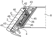
The supply devices 401 and 403 are each shown schematically at the right edge of the rack rail 3, but this is not necessarily so. The supply device can thus also be located elsewhere along the shelf rail 3 or also at its left edge. In the present case, the supply devices 401 and 403 are integrated in the rack rail 3, i.e. for example mounted or inserted in slots (not shown here, but see fig. 5).
Fig. 1 furthermore shows in each case a single wire loop L integrated into the rack rail 3, which is connected with its two loop terminals C to the supply devices 401-403 installed there. The shelf rail 3 carries shelf labels 201 and 211.
As with the shelf labels 201 and 211, the shelf rail 3 is designed such that the shelf labels 201 and 211 can be inserted into the shelf rail 3 from the front and in this case locked with the shelf rail 3 by means of a snap-in mechanism, so that the shelf rail can only be removed again from the shelf rail 3 with great effort. At the same time, the mentioned mechanism allows the shelf labels 201 and 211 to be moved along the shelf rail 3 with only a small effort compared to this and can therefore easily be placed at any position. A snapping mechanism of the described type is known, for example, from WO2017/153481a1, fig. 2. However, the mechanism can also be configured differently, as will still be discussed in detail below.
The block diagram of shelf label 201 and 211 is discussed below with respect to fig. 2. Since it is assumed in the present case that all shelf labels 201-211 are identically constructed, only a single shelf label 201 is referred to below.
The block diagram shows a first NFC interface 11 with its coil 12A, which is connected to an interface circuit 11A. Together with the interface capacitor 12B, the coil 12A forms an antenna resonant circuit 12C, by means of which signals of NFC-capable devices can be received. In the present case, the NFC capable device is a provisioning apparatus 401-403, which is configured to be NFC capable. If the coil 12A is accordingly arranged close (a few tenths of a millimeter to approximately 4 millimeters) to the loop L, as is the case in the case of a shelf label 201 arranged at the shelf rail 3, the signal emitted by means of the loop L can be received by means of the antenna resonant circuit 12C and used in the shelf label 201 for energy supply and for bidirectional communication with the associated supply device 401 and 403.
For this purpose, shelf label 201 has a so-called contactless power transmission unit 11B connected to antenna resonant circuit 12C, which contactless power transmission unit 11B has a rectifier unit 11C on the input side and a voltage regulator unit HD on the output side. In the presence of the signal, a first supply voltage VCC1 is thus generated with respect to the first reference potential GND1, which first supply voltage VCC1 has a value of approximately 2.2 volts, for example, and is provided for operating the NFC functionality of shelf label 201.
The first NFC interface 11 furthermore has a communication unit 11E, by means of which communication can be carried out according to the NFC specification or protocol. The first NFC interface has a load modulation unit 11F connected to the antenna resonance circuit 12C for load modulating the received signal in accordance with the transmit data signal TX. The other component is a protection unit 11G, which is likewise connected to the antenna resonant circuit 12C and which prevents an undesirably high input power and is designed as a signal limiter. Further, a clock generator unit 11H connected to the antenna resonance circuit 12C is provided, which generates a system clock CLK based on the received signal, which is used within the communication unit 11E. ASK demodulation unit 11I (ASK here stands for "amplitude-shift keying") that generates reception data signal RX from a small wave of the amplitude of the signal rectified by means of rectifier unit 11C constitutes another component. Furthermore, a digital control unit 11J is provided, which is clocked with a system clock CLK and processes the incoming receive data signal RX and converts it into data D and generates the outgoing transmit data signal TX from the data D.
The block diagram also shows a display unit 13A, which is divided into an electronic paper display controller 14 and an electronic paper display screen 15 controllable therewith. By means of the controller 14, the received data D is interpreted, the image content of the screen 15 is changed accordingly if necessary or status information is output in the form of data D via the first NFC interface 11 to the respective supply device 401 and 403.
In this case, the shelf label 201 has other electrical consumers, namely an input unit 13B, a time-of-flight sensor unit 13C, a temperature sensor unit 13D, and a camera unit 13E, in addition to the display unit 13A. Similar to the display unit 13A, each of these units may have its own controller Integrated Circuit (IC).
The central microcontroller unit 13 forms a further consumer, which centrally controls the data traffic of the data D and the functionality of the shelf label 201. The data processing or control takes place here in accordance with program code, which is stored in the microcontroller unit 13 and is executed with its Central Processing Unit (CPU).
All these electrical consumers 13, 13A to 13E are determined or can be determined for being operated separately in time from the presence of a signal by means of which the first supply voltage VCC1 is generated as discussed.
For this purpose, the shelf label 201 has a long-term energy storage unit 13F, which is divided into a long-term energy storage in the form of an ultracapacitor 13H and a charging stage 13G, which is designed to charge the ultracapacitor 13H, wherein, in the presence of a signal, electrical energy is stored in the ultracapacitor 13H by means of the charging stage 13G for operating the electrical consumers 13, 13A to 13E outside the time intervals in which the NFC signal is present. The charging stage 13G is connected on the input side to a first supply voltage VCC1 with respect to a first reference potential GND1, i.e., to the output of the contactless power transfer unit 11B. The charging stage provides a second supply voltage VCC2 at the output side with respect to a second reference potential GND2, wherein the first and second reference potentials GND1 and GND2 are identical, i.e. the corresponding circuit points are connected to one another.
The two supply voltages VCC1 and VCC2 may be different or identical in their values, which ultimately depends on the specifications of the consumers 13, 13A-13E to be supplied.
As soon as the second supply voltage VCC2 is sufficiently high, the electrical consumers 13, 13A to 13E start to operate and are functionally available.
In this connection, however, it has proven to be particularly advantageous for the long-term energy storage unit 13F to be constructed in a controllable manner by means of the central microcontroller unit 13. Thus, for example, the energy level of the stored energy (for example classified into three value ranges, for example good, medium, low) can be transferred to the microcontroller unit 13 by means of the energy state (signal) ES and, as a function thereof, the voltage supply for the different consumers 13A to 13E can be controlled selectively by means of the output release control signal OE output by the microcontroller unit 13 to the long-term energy storage unit 13F, as will be discussed in detail in connection with fig. 9.
Even though it is assumed in the present discussion that shelf labels 201- > 211 all have the same configuration, i.e. all have the consumers 13, 13A-13E shown in fig. 2, it should be clear at this point that this does not have to be so. Thus, for example, for each shelf rail, only a few shelf labels, e.g. 201, 203, 204, 206, 207, 209 and 211, may be implemented as shelf label displays only. Other shelf labels, for example 202, 205, 208 and 210, may not have a display unit 13A at all, but for this purpose may have a camera unit 13E and one time-of-flight sensor unit 13C each, and the last remaining shelf label 209 may finally have only a temperature sensor unit 13D. In principle, however, each combination of consumers 13A-13E can be provided for each shelf label 201-. This may be accomplished by selectively configuring the respective electrical consumers 13A-13E based on hardware in the respective shelf labels. This can also be implemented such that some or all types of consumers 13A to 13E are implemented and can be switched on by means of control commands, i.e. can be activated on the basis of software (for example by the central microcontroller unit 13) and/or can be made available or just made unavailable by specially configuring the housing of the respective shelf label 2A to 2K.
A block diagram of one of the shelf rails 3 according to fig. 1 is discussed below with respect to fig. 3. Since all supply devices 401 and 403 are identically constructed, the shelf label 403 is here representatively visualized.
The rack rail 3 carries a wire loop L fastened directly at the rack rail, which has been integrated into the rack rail. Corresponding to the position of the loop L, the shelf label display 207-. In contrast to fig. 1, the electrical connection of the loop terminal C to the electronic circuit 18A of the second NFC interface 18 of the supply device 4 is also shown. This second NFC interface 18 also has similar components to the first NFC interface 11A, with the essential difference here being that it is designed to generate and output signals, i.e. has a transmitting unit (not shown in detail). The second NFC interface 18 also has its own NFC controller (not shown). The second NFC interface 18 is designed by means of the signals output by the second NFC interface for contactless transmission of electrical energy to the shelf label display 207 and for bidirectional communication of data with the shelf label display 207 and 211 activated by the energy transmission.
The provision device 403 furthermore has an access point communication interface 19 which is designed to communicate in a radio-based manner with the access point 6 shown in fig. 1 by means of the first radio signal F1. For this purpose, the access point communication interface 19 has an electronics device (not shown in detail) constructed for this purpose and an antenna arrangement 19A, which may also comprise a plurality of antennas. The supply device 403 has a control unit 20 for controlling the internal processes and the energy supply of the shelf tags 207 & 211 and the communication with the shelf tags 207 & 211 and with the access point 6. The control unit 20 is implemented by means of a microcontroller, which is connected to the second NFC interface 18 and the access point communication interface 19 via a bidirectional data bus.
As can be seen in the overview with fig. 1, the respective supply device 401-403 is supplied with electrical energy by means of a supply transmitter 21 (also referred to as a radio energy source) which is configured for transmitting electrical energy to a receiver (i.e. one of the supply devices 401-403) by means of a focused or directed (second) radio signal F2 with a specific transmission power, such as 5W. Such a supply transmitter 21 also has a large number of antennas 22 (six are shown here) by means of which the direction of energy transmission (and ultimately the propagation of the second radio signal F2) can be adjusted relatively precisely so that the second radio signal F2 transmitting the energy arrives precisely at the respective supply device 401-403. Such energy transfer is also known under the term "Power over WiFi". It should also be mentioned at this point that the supply transmitter 21 can also be installed in the access point 6.
In order to be able to use this type of energy transfer, the supply device 403 shown in fig. 3 has a supply receiver 23 which is suitable for receiving the second radio signal F2 and which is equipped with its antenna configuration 24 (which may have a plurality of antennas) and electronics (not shown in detail). The supply receiver 23 is designed to receive the second radio signal F2 and to store the energy transmitted in this way in an internal, rechargeable electrical supply energy store 25 (for example a rechargeable battery, accumulator or "supercapacitor") and thus to generate a third supply voltage VCC3 with respect to a third reference potential GND 3. Each of the power supply devices 401-403 is operated with the internally provided third supply voltage VCC 3.
In operation, the supply device 403 can, for example, by means of its control unit 20, query or monitor the charging state of the internal supply energy store 25. As soon as the charging state drops below a certain level, the control unit 20 can request (re) charging by means of the first radio signal F1. In the case of the named proprietary time slot communication method, this can occur, for example, in the context of a status query by the access point 6. The result of this status query is received by the access point 6 and may, depending on the implementation, be forwarded directly to the provisioning transmitter 21 or, if a server 5 is included, to the provisioning transmitter 21. Since the exact geographical position (three-dimensional coordinates) of each of the supply devices 401-403 as well as its unique identifier are known in the system 1, e.g. the server 5, the supply transmitter 21 may send the second radio signal F2 precisely aimed towards the location of the respective supply device 401-403 requesting the charging. There, a second radio signal F2 is received and the energy transmitted by means of the second radio signal is used for charging the internal supply energy store 25 therein. This may also occur, in particular, when the rest of the electronics of the supplying device 403 is in a sleep state.
The "smart" shelf rail 3 described here is therefore configured by means of the supply device 401 installed in the shelf rail for contactless communication with the shelf label display 201 installed at the shelf rail and the access point 6 allocated to the shelf rail in a radio-technical manner 403. Furthermore, the shelf rail 3 is configured for providing energy in a contactless manner in the sense of energy storage in the supply means 401-403 installed in the shelf rail thereof for its own operation and for energy supply of the respective shelf label display 201-211, and during the activation of the respective first NFC interface 11 by means of the signal. Furthermore, the shelf label 201-211 is configured for autonomously energy supplying its individual consumers 13, 13A, 13B-13E even during time intervals in which there is no or no signal of the respective supply device 401-403.
In operation of the system, the access point 6 may communicate image update data to the shelf label display 201, for example, by means of a proprietary time slot communication method. The relevant supplying device 401 changes from the sleep state to the active state at its wake-up time, recognizes its synchronicity with the access point 6, and successively (in Folge) recognizes that it is addressed by the access point 6 for receiving image update data. Subsequently, in a time slot (or a series of such time slots) set for the supplying device 401, the image update data is transmitted to the supplying device 401 and at least temporarily intermediately stored. Thereafter, the electronic components of the provisioning apparatus 401 required for communication with the access point 6 are put into the sleep state again.
The provisioning apparatus 401 may forward the image update data to the associated shelf label display 201 in real time (i.e., synchronously with the communication with the access point 6) or time offset from receiving the image update data (i.e., asynchronously with the communication with the access point 6). To this end, the supply device activates its second NFC interface 18, generates and outputs a signal via its loop L, which activates the shelf label 201 installed at the uppermost shelf rail 3 and establishes a communication connection with the shelf label display 201 and transmits image update data to the shelf label display 201, where the image update data received is forwarded to the display unit 13A and processed there to change the image content. During this entire process, all shelf labels 201-203 installed at the uppermost shelf rail use this signal to charge their long-term energy storage 13H. As soon as the notification from the shelf label display 201 arrives at the supply device 401, the latter stops outputting the signal and all shelf labels 201 and 203 mounted at the uppermost shelf rail 3 deactivate at least their first NFC interface 11 as the energy transmission is cancelled. The other activities of the consumers 13, 13A-13E of the respective shelf labels 201-.
The mechanical structure of the rack rail 3, which likewise contributes to an energy-efficient operation of the system, is discussed subsequently.
Fig. 4 shows a shelf rail 3 with one of shelf labels 201 and 211, which is configured as a shelf label display 2 and which is fastened at the shelf rail. Fig. 4 furthermore shows a supply device 401 and 403 inserted laterally into the rack rail 3, which is denoted here by the reference numeral 4 in an abbreviated manner. The shelf rail 3 illustratively has a length of about 3 meters, a height of about 4.5 cm and a thickness of 1.2 cm.
Fig. 5 shows a section through the shelf rail 3. According to the section a-a drawn in fig. 4, the profile extends transversely (perpendicularly to the front side of the shelf rail 3) through the shelf rail 3. In addition, in contrast to fig. 4, the front part of the shelf bottom 8 is visible, the shelf rail 3 being fastened at said shelf bottom 8 by means of a hat rail (Hutschiene) 26 made of metal. The cap-shaped guide rails 26 constitute an electrically conductive structure for generating a defined damping ratio for the contactless energy transmission from the supply device 4 to the shelf label display 2 and for the contactless communication between the supply device 4 and the shelf label display 2. Since the antenna resonance circuit of the supply device 4 is tuned to these defined damping ratios, by means of the defined damping ratios, on the one hand the energy transfer can be optimized and on the other hand also the communication can be performed in a reliable manner. The top-hat rail 26 can be connected to the shelf base 8 by means of adhesive bonding, riveting, clamping, plugging or screwing, but this is not discussed in more detail in the figures.
The shelf rail 3 has a first fastening structure for fastening the shelf label display 2. The first fastening structure has a wall 29 extending between the top area 27 and the bottom area 28 of the shelf rail 3. Similar to the top and bottom areas 27, 28, the wall 29 also runs along the entire shelf rail 3 and forms a shelf label plane at its wall front side oriented towards the shelf label display 2, at which the shelf label display 2 is attached substantially flush with its rear wall. The first fastening structure has, in addition to the walls, a first fastening slot 30 configured at the top region 27 and extending along the top region 27 and a second fastening slot 31 configured at the bottom region 28 and extending along the bottom region 28. The fastening slots 30, 31 are configured such that the shelf label 2 with its fastening elements 32, 33 can be inserted into them in a locking manner such that the rear wall of the shelf label 2 is positioned in such a way that it is attached at the level of the shelf label. The fastening elements 32 and 33 are correspondingly positioned and configured and the housing of the shelf label 2 is sized or shaped.
The rack rail 3 furthermore has a second fastening structure for fastening the wire loop L. The second fastening structure also has a wall 29, wherein two tubes 34 are configured at the rear side of the wall. The two tubes 34 are oriented parallel to one another and extend, positioned at a defined distance of about 1 cm from one another, substantially along the entire length of the rack rail 3. The two central axes of the tube define a loop plane that runs parallel to the shelf label plane at a defined first distance of about 5 millimeters. The wall 29 here has a thickness of about 2 mm and the tube 34 is at least partially embedded in the wall 29, which allows a small distance between the plane of the thread loop and the plane of the shelf label without unnecessarily tolerating the load of the wall 29.
The shelf rail 3 furthermore has a third fastening structure for fastening the hat rail 26. The third fastening structure has two substructures which are formed on the one hand on the top side in the suspension device 35 for suspending the shelf rail 3 and on the other hand on the bottom side in the snap lip 36 for snap-in.
The third fastening structure furthermore has a first spacer element 37 positioned at the top region 27 and a second spacer element 38 positioned at the bottom region 28. The two spacer elements 37 and 38 serve to fix and to maintain a defined second distance of the cap rail 26 from the plane of the wire loop, wherein a substantially parallel orientation of the planar structure of the cap rail 26 relative to the plane of the wire loop is also achieved here. Two spacer elements 37 and 38 are oriented substantially at an angle of 90 ° away from the rear side of the wall and extend from the wall 29 towards the hat rail 26, where they contact the hat rail 26 and ensure the nominal position. In the present case, the hat-shaped guide rail 26 is positioned at a second distance of about 7 mm from the plane of the wire loop. The hat-shaped rail 26 itself has a thickness of about 1 mm. The height of the hat-shaped guide rail is approximately 2.5 cm, whereby the brim, which is still approximately 5 mm long on the top side and on the bottom side, respectively, extends closely over an edge that is set back by approximately 3 mm, with which the interaction with the plastic body of the shelf guide rail 3 takes place. The length of the hat-shaped guide rail 26 corresponds approximately to the length of the shelf guide rail 3.
In addition, the outer expansion of the coil 12A formed at the rear wall of the shelf label display 2 is entered in fig. 5 by means of a dimensioning 39. It is clearly visible here that the coil 12A is attached flat at the shelf label plane and is arranged there in correspondence or even overlapping with the spatial expansion of the wire loop L measured in the direction of the height of the shelf rail 2.
The shelf rail 3 furthermore has a fourth fastening structure for fastening the supply device 4 in order to push and fix the supply device 4 between the wall 29 of the shelf rail 3 and the cap rail 26 fastened by means of the third fastening structure at an end region (left end or right end) of the shelf rail 3, so that the wire loop terminal C of the wire loop L available there is in contact with the supply device 4. For this purpose, the fourth fastening structure has a first insertion channel 40, which is configured below the first spacer element 37 at the wall rear side and is open towards the bottom region 28, and a second insertion channel 41, which is configured above the second snap lip at the wall rear side and is open towards the top region 27. The supply device 4, which may have its fastening rail 42, which is visible in fig. 6, is pushed into the two insertion channels 40 and 41. Furthermore, the fourth fastening structure has a circular hole 43 positioned at the top side end of the wall 29 and at the bottom side end of the wall 29, into which a fastening screw 44 (see e.g. fig. 6, but also 9 and 10) can be screwed from the side of the rack rail 3 for screwing the supply device 4 with the rack rail 3.
Fig. 6 shows a section through the shelf rail 3 according to section B-B drawn in fig. 4, which is oriented transversely (oriented perpendicularly to the front side of the shelf rail 3) through the shelf rail 3 and extends from the right side of section a-a at that point of the shelf rail 3 at which the contact element 45 of the supply device 4 is formed. For improved clarity, a number of reference numerals not directly related to the fastening of the supply device 4 are hidden in fig. 6.
Furthermore, in the present case two contact surfaces 46 are provided, wherein each of the contact surfaces 46 is welded to one of the ring terminals C. With the feeding device 4 completely pushed into the rack rail 3, i.e. when it is positioned in the nominal position, the contact surface 46 is brought into contact with the contact element 45, which is designed as a spring contact, so that a connection L is established with the wire loop and said wire loop can be used as a component of the second NFC interface 18. However, unlike this configuration, when the contact elements 45 are positioned closer to each other, the contact surface 46 may not be required, and the wires constituting the wire loop L may be directly contacted at the end region of the wires provided as the loop terminal C.
It should also be mentioned that at the other end of the rack rail 3, more precisely at the other end of the tube 34, the wire of the wire loop L runs in one piece from one tube 34 to the other tube 34.
Fig. 7 and 8 are also discussed, wherein fig. 7 shows the supply device 4 pulled out of the rack rail 3 only slightly, and fig. 8 also shows the contact element 45 in a slightly modified illustration. Here, most of the number of reference numerals are not needed in order not to overload the illustration.
In fig. 9, the long-term energy storage unit 13F (hereinafter referred to as unit 13F) is discussed in more detail in a further developed constructive manner. As can already be seen from fig. 2, the unit 13F is fed by a power transmission unit 11B, which power transmission unit 11B generates a first supply voltage VCC1 on the output side when a (NFC) signal is present at the coil 12A. Depending on the quality of the NFC signal, the first supply voltage VCC1 may fluctuate.
On the input side, the unit 13F has a first voltage regulator stage (voltage regulator) 100, which provides a regulated dc voltage of a defined value for a subsequent charging and current limiter stage (charger and current limiter) 101. Stage 101 causes the load to be limited and causes the charging current to be limited so that the NFC signal is less strongly loaded and does not collapse. This may be important so that other shelf labels mounted at the same shelf rail 3 may be supplied as well and communication with the other shelf labels may be performed as well. Said stage furthermore causes the supercapacitor 13H to be correctly (according to its specifications) charged.
The unit 13F furthermore has a cold start stage (cold start) 102, which is designed to actuate a first electronic switching stage 103. The cold start stage 102 is responsible for: only when the charge of the supercapacitor 13H has reached a minimum level, the electronics downstream of the first switching stage 103 are supplied from the supercapacitor 13H, so that continuous operation of the downstream electronics is possible, and the voltage of the supercapacitor 13H does not drop so strongly, due to loading with the downstream electronics, that the downstream electronics will stop their operation again. If the necessary minimum charge level is reached, the cold start stage 102 switches the second voltage regulator stage 104 by means of the first switching stage 103 to the supercapacitor 13H, at which supercapacitor 13H, for example, a maximum voltage of 2.2 volts can be tapped. By means of the second voltage regulator stage 104, a higher (multiplied) supply voltage VCC2_1 of approximately 3 volts is generated, which is necessary for operating the central microcontroller unit 13 and is output to the central microcontroller unit 13. Whereupon the central microcontroller unit begins its operation. In this state, the microcontroller unit 13 can already exchange data D with the digital control unit 11J and can therefore also decode and, if necessary, also execute commands received via the first NFC interface 11 or receive or transmit data D.
Furthermore, the unit 13F has an energy threshold detection stage 105 which is designed to subdivide the energy stored in the supercapacitor 13H, for example, into three categories, and to transmit this information, for example, as an energy state ES (for example in the form of "good", "medium" or "bad") to the microcontroller unit 13.
Depending on the energy state ES present, the microcontroller unit 13 then decides which of the electrical consumers 13A to 13E can be supplied with its respective supply voltage VCC2_1 or VCC2_2, taking into account whether the respective electrical consumer 13A to 13E can be supplied at all (reasonably), which can be derived, for example, from the received data D or commands. The microcontroller unit 13 thus decides which consumers 13A-13E can draw current from the supercapacitor 13H. Therefore, the supply voltage VCC2_1 is turned on for the display unit 13A, for example, only when there is an energy status "good". It is then possible to change the image content of the screen 15 and thereafter to stop the power supply to the display unit 13A. In order to keep the energy consumption from the supercapacitor 13H as low as possible.
In order to enable the individual supply voltages VCC2_1 or VCC2_2 of the individual consumers 13A to 13E to be switched on and off, the unit 13F has an output control stage (output-control) 106, which is controlled by means of an output release control signal OE of the microcontroller unit 13. The output control stage converts the output release control signal OE into a switching signal for the two other switching stages 107 and 108.
By means of the second switching stage 107, it is thus possible, for example, to also supply the supply voltage VCC2_1 provided for the microcontroller unit 13 to the consumers 13A to 13B, while for the consumers 13C to 13E, the supply voltage VCC2_2 having a different value (for example 5 volts) than the supply voltage VCC2_1 can be switched on by means of the third switching stage 109, said value being generated by means of the third voltage regulator stage 109.
Of course, this action can also be applied individually for each load 13A to 13E if a corresponding number of switching stages and, if appropriate, also a corresponding number of voltage regulators are provided as a function of the number of loads.
Finally, it is once again pointed out that the figures described in detail above are merely embodiments which can be modified in various ways by a person skilled in the art without departing from the scope of the invention. For the sake of completeness, it is also pointed out that the use of the indefinite article "a" or "an" does not exclude that a relevant feature may also be present several times.