Background
Rotary filling machines are commonly used to dispense dry materials into containers from above. Such machines typically include a rotating turntable located below a rotating combination weigher or other device that transports the material to be dispensed. The turntable supports a plurality of circumferentially spaced buckets or pods having a lower opening. The opening of each bucket or pod cooperates with the underlying funnel. In operation, each bucket receives a specified amount of material as it rotates under the conveyor and discharges the material into an associated hopper. The material then flows through the hopper and is dispensed into a lower receptacle circumferentially spaced from the transfer device.
The dispensing of some materials can be problematic because they tend to "bridge" or span gaps and material paths in the filling device and clog the device. Some such materials are relatively sticky or have high adhesion, which can result in the materials clumping or sticking to each other and/or to the bucket or funnel. Typical of such materials are "fondants," which are relatively soft, chewable confections. Fondants are typically, but not always, gelatin-based. They are most commonly used in confectionery, but also in other materials, such as chewable vitamins and pharmaceuticals. They vary in size and shape, but most are "bite-sized", i.e., less than 5cm in maximum diameter. Some "fondants" take on the appearance of fantasy or stylized animals, such as bears or fish. Others are in the form of generally oval shaped tablets. They may or may not have a sugar coating. The tendency of these materials to clump together and stick to the surfaces of the filling machine creates a tendency to bridge or clog portions of the flow path, such as the bottom opening of a bucket or the throat of a funnel. Bridging is of particular concern when filling containers having relatively small diameter filling openings with materials formed from relatively large diameter particles, since the particles must be guided through relatively small filling openings, the diameter of which is sometimes only 2-3 times the maximum particle diameter. Even if they do not bridge sufficiently to block the flow path, the material may still stick to surfaces (e.g., the bottom of the bucket adjacent the bottom opening or the side surface of the funnel) long enough to delay or prevent dispensing into the container below, or at least fall into the container in pieces rather than one at a time. The resulting delay/blockage can result in reduced fill accuracy, including partially filled and unfilled conditions.
Other materials are not as sticky as traditional fondants, but still entangle with each other, thereby spanning an opening or space. Some nuts, such as cashews, exhibit this characteristic.
Thus as used herein, "bridgeable material" refers to any discrete dry particles having a relatively high tendency to clump and/or adhere to other surfaces by adhering and/or entangling with each other. Bridging materials include, for example, gummy or soft candies with high adhesion characteristics, and some nuts that are prone to tangling, such as cashews.
Accordingly, there is a need to provide a rotary filling machine that can reliably dispense bridgeable dry material in a controlled and predictable manner.
It is further desirable to provide a rotary filling machine that meters the dispensing of a bridgeable material in a manner that reduces or prevents clumping and/or bridging.
It is also desirable to provide a rotary filling machine that "separates" the dispensed bridgeable material so that they can be dispensed into containers, typically one at a time, rather than in chunks or batches.
Disclosure of Invention
According to a first aspect of the invention, a rotary filling machine comprises: a rotatable central hub having an opening extending vertically therethrough, a plurality of circumferentially spaced buckets above the opening, and a plurality of funnel assemblies mounted on the hub below the opening. Each bucket has an open top, an open bottom aligned with the opening in the wear plate, and a perimeter wall. Each funnel assembly has an upper inlet positioned below the bottom opening of the respective bucket, and a lower dispensing outlet. The fixed slide plate is vertically positioned between the funnel component and the bucket. The slide plate has an upstream end, a downstream end, an upper surface and a lower surface, and an inner edge and an outer edge, when viewed in the direction of rotation of the turntable. The slide plate includes a tapered portion that tapers in diameter toward its downstream end such that the diameter of the flow path from the bottom of the bucket to the inlet opening of the funnel assembly gradually increases as the slide plate tapers.
The inner edge of the tapered portion of the slide plate may taper continuously and uniformly over at least a majority of the tapered portion.
Each bucket may have opposing first and second end walls (upstream and downstream end walls) and inner and outer walls, each of which adjoins an associated end of both end walls. In this case, each bucket may have at least one partition extending at least substantially vertically between the inner and outer walls to define discrete compartments within the bucket.
Each funnel assembly may have an internal dispersion chamber sized and configured to gradually disperse material falling therefrom. The dispersion chamber of each funnel assembly is bounded by opposing first and second upper walls and opposing first and second lower walls. The walls are positioned and configured such that material impinging on the first upper wall is directed to the second lower wall and thereby out of the dispersion chamber.
In one configuration, the dispersion chamber is located in the upper funnel and the lower funnel presents a flow path having a lower portion that is inclined at an acute angle relative to an upper portion thereof.
The rotary filling machine may further include a hopper rapper positioned to resiliently impact the hopper assembly during rotation of the rotary filling machine.
According to another aspect of the present invention, a funnel assembly for dispensing material into a container is provided. The funnel assembly includes an upper funnel and a lower funnel. The upper funnel has an internal dispersion chamber sized and configured to gradually disperse the dry, bridgeable material falling therefrom. The dispersion chamber of the upper funnel may be bounded by opposing first and second upper walls and opposing first and second lower walls. In this case, the walls are positioned and configured such that material impinging on the first upper wall is directed to the second lower wall and thereby flows out of the dispersion chamber.
A plurality of fingers may project into each funnel assembly between the inlet and the outlet and proximate an axial centerline of the funnel assembly.
These and other features and aspects of the present invention will be better appreciated and understood when considered in conjunction with the following description and the accompanying drawings. It should be understood, however, that the following description, while indicating preferred embodiments of the present invention, is given by way of illustration and not of limitation.
Detailed Description
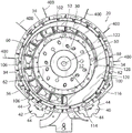
Turning first to fig. 1-3, a rotary filling machine 20 constructed in accordance with the present invention is shown. The rotary filling machine 20 is configured to receive the bridgeable dry material (as that term is defined above) from the transfer system and dispense the material in a controlled manner into the underlying container. The "controlled" manner may be a specified number of particles per receptacle, a specified weight of particles per receptacle, or a specified volume of particles per receptacle. In the illustrated embodiment, the transport system includes a rotating combination scale 22, the rotating combination scale 22 receiving material from a conveyor (not shown) and dispensing a given weight of material in each batch. If, as is usual, the average number of particles per given weight is known, the rotary combination weigher 22 thus dispenses a given number of particles per batch. Once such a rotary combination scale is available through Yamoto, it may be provided by any number of suppliers. The illustrated rotary filling machine is optimized to fill bottles with fondant having a maximum size of about 2.25cm and dispense the fondant into bottles having a filling opening diameter of 4.25cm to 4.50 cm. The machine configuration, and in particular the configuration of the hopper assembly described below, may vary significantly depending on the size and characteristics of the particles being processed and the diameter of the filling opening of the container being filled.
Still referring to fig. 1-3, the rotary filling machine 20 includes a rotary turntable 30 supporting a plurality (18) of circumferentially spaced buckets 32 and an equal number of hopper assemblies 34, one hopper assembly 34 associated with each bucket 32. As many container holders 36 (it should be understood that "container" as used herein refers to any receptacle configured to receive material from the funnel assembly) are mounted on the bottom of the hub 30 below the funnel assembly 34 for receiving a container to be filled. Furthermore, it is important that a stationary skid 100 (first seen in fig. 4) is mounted on the turntable 30, vertically between the bucket 32 and the funnel assembly 34, for spreading or separating the flow of material from the bucket 32 to the funnel assembly 34.
The container 37 (fig. 9 and 10) of this particular embodiment is a bottle, and the container holder 36 may be considered a bottle holder. Each bottle holder 36 has a notch 38, the notch 38 being configured for a particular bottle shape and size to receive a bottle 37 to hold the bottle in place under the associated funnel assembly 34 during a filling operation. The bottles are transferred to and received by the container holders 36 by a conveyor (not shown) which transfers the empty bottles to an upstream conveyor 40 and receives the empty bottles from the most downstream bottle holder 36 by a downstream conveyor 42. Each conveyor 40, 42 has a plurality of circumferentially spaced peripheral notches 44, each notch 44 rotating into and out of mating engagement with a notch 38 of an associated bottle holder 36 to convey bottles between the bottle holder 36 and the conveyor. The conveyors and conveyors 40, 42 are configured to operate in synchronization with the turret 30. Different supply and handling systems may be used for containers other than bottles.
Referring to fig. 1-5, the turntable 30 includes a central shaft 50 and upper and lower disc devices 52 and 54. The shaft 50 is driven by a motor (not shown). An upper disc means or "filler plate" 52 is secured to the shaft 50 and has a segmented circular opening near its outer periphery, each segment of which forms a fill opening 56, the fill openings 56 being aligned with the buckets 32 from above and with the funnel assemblies 34 from below. Each fill opening 56 of this exemplary embodiment is approximately 15cm long and approximately 10cm wide. The bucket 32 is mounted on the fill plate 52 inside the fill opening 56. A mount is also formed on or within the filler plate 52 for receiving the funnel assembly 34. These mounts may take the form of openings configured to mate with magnetic quick mount devices of the type described in commonly assigned U.S. patent No.8,991,442, the subject matter of which is incorporated herein by reference in its entirety. Alternatively, each mount may include spaced holes for receiving spaced bolts that mount the funnel assembly 34 on the bottom of the fill plate 52.
In the illustrated embodiment, the
filler plate 52 is formed of stainless steel or a similar durable, easy to clean material. An annular rotating wear plate formed by an annular
inner ring 60 and an annular
outer ring 62 is mounted on top of the stainless
steel fill plate 52, the annular
inner ring 60 and the annular
outer ring 62 being located radially inward and outward of the
fill opening 56, respectively. The
rings 60 and 62 are formed of a material that is relatively hard and wear resistant, but has a relatively low coefficient of sliding friction. HDPE (high density polyethylene),
(an acetal homopolymer) and UHMW (ultra high molecular weight polyethylene) are examples of suitable materials, but other materials with similar properties can be used based on availability and product interaction. An annular opening is formed between the
inner ring 60 and the
outer ring 62 above the
fill opening 56. The
buckets 32 are supported on the upper surfaces of wear plate rings 60 and 62 and are attached to the
hub 30 as described below.
Still referring to fig. 1-4, each bucket 32 is formed of a material that is durable and easy to clean and has a relatively low coefficient of sliding friction. Any of various grades of stainless steel and materials with similar properties based on product interaction and environment are sufficient. The material may be dimpled or otherwise altered to inhibit sticking of tacky particles thereto. In this embodiment, each bucket 32 is generally trapezoidal in shape, having first and second opposing end walls 64 and 66 or upstream and downstream opposing end walls 64 and 66 that rotate counterclockwise, and radially inner and outer walls 68 and 70, respectively, the radially inner and outer walls 68 and 70 abutting associated ends of both end walls 64 and 66. The outer wall 70 of each bucket 32 is longer than the inner wall 68 and the end walls 64 and 66 are inclined relative to the radial bisector of the turntable assembly, thereby providing a trapezoidal shape that allows the bucket 32 to cover the entire circular area containing the bucket 32 without an intervening gap. The upper ends of the inner and outer end walls 64, 66 flare outwardly to serve as a chute for directing material into the interior of the bucket 32 that might otherwise miss the bucket 32. Such as six buckets may be provided in the form of semi-circular subassemblies. A semi-circular flange 72 extends rearwardly from the bucket 32. As best seen in fig. 5, each subassembly is held in place by a plurality of spring-loaded plungers 74, which plungers 74 extend through openings 76 in flange 72 and selectively engage corresponding grooves 78 in wear plate inner ring 60 to lock the subassembly in place.
Still referring to fig. 1-4, and particularly to fig. 4, to prevent material received from the rotary combination weigher 22 from simply being pushed in front of the upstream end wall 64 of each bucket 32 (which is particularly noticeable for relatively small fills), each bucket 32 may have at least one partition extending at least generally vertically from the bottom of the bucket 32 between an inner wall 68 and an outer wall 70. In the illustrated embodiment, two equidistant partitions 80 are provided, each extending at least generally parallel to each other and to the front end wall 64 of the bucket 32. Three discrete chambers are thus formed within the bucket 32. During relatively small fills, most or all of the particles are batch-dispensed into the most downstream chamber. The benefits of this effect will be discussed in more detail below.
Referring to fig. 3-7, a skid plate or "drop plate" 100 is mounted to the wear plate
inner ring 60 and wear plateIn the upper groove between the
outer rings 62 to remain in place as the
rings 60 and 62 rotate thereunder. The
skateboard 100 may be made of
Or the like, to facilitate such sliding contact while still providing the desired hardness and wear resistance. However, it may be formed of a material different from that of the wear plate rings 60 and 62 to facilitate sliding movement of the two components relative to each other. For example, Delrin is particularly suitable for use in the
skate 100 if HDPE is used as the wear plate rings 60 and 62. The
slide plate 100 shown in FIG. 7 is formed integrally with an
annular ring 102, the
annular ring 102 being segmented by a plurality of circumferentially spaced apart
radial connecting arms 104. The inner and
outer edges 106, 108 of the
ring 102 are supported on upwardly facing
lips 110, 112 formed on the outer circumferential surface of the wear plate
inner ring 60 and the inner circumferential surface of the wear plate
outer ring 62, respectively, as best seen in fig. 5. The
ring 102 prevents material from accumulating on the
lips 110 and 112 during the filling operation. The
skateboard 100 is held stationary by a pin or similar device 114 (fig. 1, 3 and 6) that extends downwardly from the fixed mount into an opening formed in or through the
skateboard 100. Accurate relative positioning of the
slide plate 100 with respect to the
rings 60 and 62 of the wear plate may be provided by forming the openings in the form of slots or by providing two or more spaced
circular openings 116 as shown in fig. 7.
With particular reference to FIG. 7, the radial diameter of the slide plate 100 is tapered over at least a portion of its length such that the effective size of the fill opening 56 encountered by the material in the rotating bucket 32 gradually increases downstream of the rotating combination scale dispenser 22. The tapered portion 122 thus effectively acts as a sliding shutter which causes the rotating bucket 32 to push particles into the fill opening 56 one at a time or in small groups rather than in individual pieces. Thus, the most upstream fill opening encountered by the filled bucket 32 is almost completely covered, and the subsequently encountered downstream fill opening 6 is gradually exposed until the fill opening 56 downstream of the skid plate 100 is completely exposed.
More specifically, as best seen in fig. 5-7, the slide plate 100 includes an upstream end 120 that is irregular in diameter and a downstream end 122 that tapers in diameter toward its downstream end when viewed in the direction of rotation of the turntable. In the illustrated embodiment where the slide plate extends through an arc of approximately 290 degrees, the tapered section 122 extends through the most downstream 170 and 250 degrees of the slide plate 100. The taper may be continuous and uniform along a portion or all of the tapered portion 122. In the illustrated embodiment, the tapered portion has an arc length of about 235 degrees. The tapered inner edge 124 has a radius of about 17 degrees over the most upstream about 60 degrees of the tapered section and a radius of about 18.5 degrees over the remaining 175 degrees.
The notch 128 is formed in the inner edge 124 of the upstream end of the tapered portion 122 so that the tapered leading end is located above the associated fill opening 56, rather than being disposed inboard of the fill opening. In the illustrated embodiment where the fill opening 56 is approximately 100mm wide, the "effective width" of the fill opening 56, as defined by the portion of the fill opening 56 not covered by the slide plate 100, increases in diameter from approximately 12mm at the most upstream end of the tapered portion 122 to the full 100mm at the most downstream end of the slide plate 100, where the slide plate is not wider than the lip 112 on the wear plate outer ring 62.
Still referring to fig. 5-7, the upstream end 120 of the sled 100 completely covers the underlying fill opening(s) 56 to provide a gapless "receiving surface" for receiving bulk dispensed pellets received from the rotary combination weigher 22 and grading them for subsequent dispensing into the fill openings when they are exposed. In the illustrated embodiment, the upstream portion has an arc length of about 55-60 degrees. The arc length can be quite long, if desired.
It should be noted that the ring 102 of FIG. 7 is not necessary for support or operation of the skateboard 100. The slide plate 100 or a similarly configured slide plate may be provided in the form of a crescent or half moon shaped element without a ring. The slide 100 is shown without a ring in fig. 6.
Referring now to fig. 8-10, each funnel assembly 34 is configured to dispense material falling through the associated fill opening 56 while further dispersing the material such that the material is dispensed from the bottom dispensing outlet 160 of the funnel assembly 34 in a single or near single column rather than in blocks. The diameter of the outlet 160 is typically no greater than the diameter of the inlet of the vessel below, or in this non-limiting example, about 20mm to 40mm, more typically about 30 mm. The internal geometry of each funnel assembly 34 may be customized to accommodate the flow characteristics of the material being dispensed. As a rule of thumb, the product flow path should be relatively simple for materials that are relatively sticky or tacky but not particularly prone to tangling (e.g. soft pastries), and relatively complex for materials that are not sticky or sticky but are very prone to tangling or at least self-adhesion (e.g. cashews or hard pastries).
The funnel assembly 34 shown in fig. 8-10 is well suited for dispensing the latter type of material. The illustrated funnel assembly 34 includes an upper funnel 130 and a lower funnel 132 coupled to one another by a flexible bellows 134. The bellows 134 is held in place by a snap fit on a lower annular flange 136 on the upper funnel 130 and an upper annular flange 138 on the lower funnel 132. The upper funnel 130 may be generic to all dispensed materials or a wide variety of material classes. The lower funnel 132 may be customized for a particular product, most notably including for particle diameter, and thus may be considered a container adapter. The interior of each funnel assembly 34 may be non-linear and non-uniform in volume taper to cause the material falling therefrom to zigzag or bounce side-to-side, thereby breaking up clumps of tangled particles and further dispersing or separating the flowing stream of particles. This effect can be achieved with a variety of geometries, some of which are more effective on certain particles than others.
With particular reference to fig. 9, the interior of the upper funnel 130 defines an interior dispersion chamber bounded by an upper set of opposing first and second walls 140, 142 and a lower set of first and second lower walls 144, 146. Each set of walls may be provided on the inner surface of a removable insert 148 (or two or more stacked inserts) that the insert 148 may drop into the housing 150 of the upper funnel 130 from above to allow for customization for a particular application. The insert 148 and the lower funnel 132 may be made of a durable, wear-resistant, low-friction material (e.g., urethane). The first walls 140 of the upper set slope downwardly and inwardly to a bottom edge located near the axial center of the upper funnel 130. At least a majority of the particles swept into the hopper assembly 34 strike the wall 140 and are transferred to the lower set of opposing second walls 146. The second wall 146 of the lower set slopes downwardly and inwardly to the bottom edge of the inlet that directs particles to the lower funnel 132. The upper set of second walls 142 and the lower set of first walls 144 act primarily as stops and little or no product flow is seen.
Still referring to fig. 9, the bottom funnel 132 is curved or "bent like a dog's hind leg" at its central portion 151 to define upper and lower portions that extend at an acute angle relative to each other. As with the upper funnel 130, the interior of the lower funnel 132 has first and second upper walls 152, 154 and first and second lower walls 156, 158. The first walls 152 of the upper set slope downwardly and inwardly to the bottom edge. The second set of second walls 158 slope downwardly and inwardly to a bottom outlet 160 of the funnel assembly 34. Particles bouncing off the first wall 152 of the upper group strike the second wall 158 of the lower group where they are further separated as the particles flow to the lower outlet 160. The upper set of second walls 142 and the second set of first walls 152 act primarily as stops and little or no product flow is seen.
Comparing fig. 9 to 10, it can be seen that the lower portion of the opening in the lower funnel 132 is tapered at least in one direction or "X" direction as shown in fig. 9, and widened in the other direction or "Y" direction as shown in fig. 10. Although tapered in one direction for orientation purposes, this geometry helps prevent bridging of particles at the bottom outlet 160 by maintaining a relatively large flow area at the outlet.
Referring now to fig. 12, the funnel assembly 234 may be fitted with inwardly projecting fingers 380 for being struck by and breaking up any pieces that may survive dropping through the upper funnel 330. The funnel assembly 234 of this embodiment is otherwise similar to the first embodiment in that it has an upper funnel 330 and a lower funnel 332 coupled by a flexible bellows 334. Fingers 380 project inwardly into the bezel 334 from the outer periphery of the bezel 334. Three such fingers (two of which are shown in fig. 12) are provided in the illustrated embodiment, equally spaced around the funnel assembly 234. Each finger has an inner product engaging end, which may have a tab thereon, and an outer end that is clamped between an upper surface of the bellows 334 and a lower surface of the mounting flange 336 of the upper funnel 330. The fingers 380 may be inclined at any desired angle relative to the horizontal to achieve the desired scrambling effect, and their angles of inclination may be different relative to each other. The fingers 380 may be formed of, for example, stainless steel or spring steel.
The material flow path in the funnel assembly 234 of fig. 12 is also straighter or more linear than the material flow path in the funnel assembly 34 of fig. 8-10 to accommodate more tacky or sticky materials that tend to adhere to any surface they contact. In this embodiment, both the upper funnel 330 and the lower funnel 332 are at least predominantly frustoconical. Thus, sharp turns in the lower funnel 132 are eliminated. Furthermore, in the upper funnel 330, the first and second sets of walls having different relative inclinations are replaced by a single peripheral wall 340 having a relatively uniform inclination.
Of course, the fingers 380 of fig. 12, as well as other fingers or other elements that protrude into the funnel assembly to aid in breaking up the pieces, may also be provided in the funnel assembly of fig. 8-10.
Referring to fig. 3, 5 and 11, additional measures may be provided to apply an impact or vibration to the hopper assembly 34 to dislodge particles that tend to bridge the hopper or stick to its inner walls. In the illustrated embodiment, these provisions take the form of a "funnel rapper" 400 that is impacted by the rotating funnel assembly 34. A plurality of such funnel rappers 400 may be spaced around the filling machine 20 in cooperation with some or all of the funnel assemblies that actually dispense product at any given time. Six such hopper rappers 400 are provided in this embodiment and are circumferentially spaced about the filling machine 20 between the upstream end of the tapered portion 122 of the sled 100 (where the particles first fall into the hopper assembly 34 below) and a location disposed downstream of the downstream end of the sled 100.
Each funnel rapper 400 includes a rigidly mounted arm 402, a spring arm 404, and a strike block 406. Each mounting arm 402 has a base 408 that is bolted to a stationary support surface of the filling machine 20. Each spring arm 404 is relatively flexible and may be formed of spring steel, for example. Each spring arm 404 has a first end fixed to the mounting arm 402 and a second free end positioned in the rotational path of the funnel assembly. The radial position of the spring arm 404 relative to the mounting arm 402 may be adjustable, for example, by providing a slot 410 in the spring arm 404 that mates with a spaced hole 412 in the mounting arm 402. The impact block 406 is mounted to the free end of the spring arm 404 by a bolt 414, the bolt 414 extending through the impact block 406, through the spring arm 404 and into a mounting block 416 located behind the spring arm 404. The mounting block 416 provides additional mass to the structure deflected by the rotating funnel assembly 34. The impact block 406 is formed of a durable, wear-resistant material (e.g., Delrin). In operation, engagement of the impact block 406 with the rotating funnel assembly causes the free end of the spring arm 404 to resiliently deflect out of the path of rotation of the funnel assembly while applying an impact to the funnel assembly 34.
In operation, the turntable 30 of the rotary filling machine 20 is driven to rotate while pellets of bridgeable material are deposited from the rotary combination weigher dispenser 22 into the bucket 32. The particles in each bucket 32 initially fall onto the skid 100 and are swept one at a time or in small groups into the fill opening 56 as the bucket 32 rotates over the tapered portion 122 of the skid 100, tending to separate the particles or, from another perspective, to break up the stream of particles into individual particles or small chunks of particles. If the batch dispensed is relatively small so as not to fill the bottom of the bucket 32, the baffle may impede the "scooping up" of particles along the edge of the opening adjacent the slide plate 100, rather than sweeping such particles into the fill opening 56.
If the funnel assembly 34 is of the serpentine type as shown in fig. 1-10, the material filled into the funnel assembly 34 will further separate or disperse as it rebounds from the upper and lower funnels 130, 132 before falling from the discharge outlet 160 into the container 37. The falling particles are further separated or dispersed during this process, resulting in the material being dispensed into the lower vessel 37 in a stream of mostly unitary particles. During this process, the impact of the funnel rapper 400 on the funnel assembly 34 will inhibit or prevent particles from adhering to any particular surface of the funnel assembly, with a concomitant reduced risk of bridging.
On the other hand, if the funnel assembly 234 has a more conventional orientation as shown in fig. 12, the material simply falls through the funnels 330 and 332 and out the discharge opening. Any piece of material will impact one or more of the fingers 380, tending to separate particles falling past the fingers. Such fingers may also be provided in the funnel assembly 34.
Variations and modifications of the foregoing are within the scope of the present invention. Some such variations and modifications are discussed above. Other variations and modifications will become apparent from the appended claims. Many changes and modifications may be made to the invention without departing from the spirit thereof. The scope of such changes and modifications will become apparent from the appended claims.