CN114577111A - Surface shape detection system and detection method - Google Patents
Surface shape detection system and detection method Download PDFInfo
- Publication number
- CN114577111A CN114577111A CN202210263969.2A CN202210263969A CN114577111A CN 114577111 A CN114577111 A CN 114577111A CN 202210263969 A CN202210263969 A CN 202210263969A CN 114577111 A CN114577111 A CN 114577111A
- Authority
- CN
- China
- Prior art keywords
- light
- detection
- rgb
- polarization
- color
- Prior art date
- Legal status (The legal status is an assumption and is not a legal conclusion. Google has not performed a legal analysis and makes no representation as to the accuracy of the status listed.)
- Pending
Links
- 238000001514 detection method Methods 0.000 title claims abstract description 93
- 230000010287 polarization Effects 0.000 claims abstract description 77
- 230000003287 optical effect Effects 0.000 claims abstract description 22
- 238000005259 measurement Methods 0.000 claims abstract description 18
- 230000001052 transient effect Effects 0.000 claims abstract description 15
- 238000004364 calculation method Methods 0.000 claims abstract description 14
- 230000010363 phase shift Effects 0.000 claims abstract description 14
- 230000008878 coupling Effects 0.000 claims abstract description 10
- 238000010168 coupling process Methods 0.000 claims abstract description 10
- 238000005859 coupling reaction Methods 0.000 claims abstract description 10
- 239000013307 optical fiber Substances 0.000 claims description 33
- 238000009826 distribution Methods 0.000 claims description 18
- 238000005516 engineering process Methods 0.000 claims description 13
- 230000005540 biological transmission Effects 0.000 claims description 8
- 238000003384 imaging method Methods 0.000 claims description 6
- 238000012360 testing method Methods 0.000 claims description 4
- 239000000835 fiber Substances 0.000 claims 3
- 230000001815 facial effect Effects 0.000 claims 2
- 238000003491 array Methods 0.000 abstract description 4
- 238000000605 extraction Methods 0.000 abstract description 3
- 238000000926 separation method Methods 0.000 abstract description 3
- 230000006872 improvement Effects 0.000 description 8
- 238000000034 method Methods 0.000 description 6
- 239000011521 glass Substances 0.000 description 3
- 238000005305 interferometry Methods 0.000 description 3
- 238000002310 reflectometry Methods 0.000 description 3
- 239000000758 substrate Substances 0.000 description 3
- 239000000919 ceramic Substances 0.000 description 2
- 238000012545 processing Methods 0.000 description 2
- 230000004075 alteration Effects 0.000 description 1
- 230000009286 beneficial effect Effects 0.000 description 1
- 230000008859 change Effects 0.000 description 1
- 238000004891 communication Methods 0.000 description 1
- 238000011161 development Methods 0.000 description 1
- 238000010586 diagram Methods 0.000 description 1
- 230000007613 environmental effect Effects 0.000 description 1
- 238000011156 evaluation Methods 0.000 description 1
- 230000001678 irradiating effect Effects 0.000 description 1
- 238000002372 labelling Methods 0.000 description 1
- 238000004519 manufacturing process Methods 0.000 description 1
- 239000000463 material Substances 0.000 description 1
- 230000008569 process Effects 0.000 description 1
- 238000005070 sampling Methods 0.000 description 1
- 238000006467 substitution reaction Methods 0.000 description 1
- 238000002834 transmittance Methods 0.000 description 1
Images
Classifications
-
- G—PHYSICS
- G01—MEASURING; TESTING
- G01B—MEASURING LENGTH, THICKNESS OR SIMILAR LINEAR DIMENSIONS; MEASURING ANGLES; MEASURING AREAS; MEASURING IRREGULARITIES OF SURFACES OR CONTOURS
- G01B9/00—Measuring instruments characterised by the use of optical techniques
- G01B9/02—Interferometers
-
- G—PHYSICS
- G01—MEASURING; TESTING
- G01B—MEASURING LENGTH, THICKNESS OR SIMILAR LINEAR DIMENSIONS; MEASURING ANGLES; MEASURING AREAS; MEASURING IRREGULARITIES OF SURFACES OR CONTOURS
- G01B11/00—Measuring arrangements characterised by the use of optical techniques
- G01B11/24—Measuring arrangements characterised by the use of optical techniques for measuring contours or curvatures
- G01B11/2441—Measuring arrangements characterised by the use of optical techniques for measuring contours or curvatures using interferometry
Landscapes
- Physics & Mathematics (AREA)
- General Physics & Mathematics (AREA)
- Length Measuring Devices By Optical Means (AREA)
Abstract
The invention discloses a surface shape detection system which comprises an optical coupling unit, a Miller polarization interference unit and a detection calculation unit, wherein the optical coupling unit comprises a beam combination assembly and a beam expansion system, the Miller polarization interference unit comprises a microscope objective, a polarization beam splitting plate and a reference reflector, and the detection calculation unit comprises a quarter-wave plate, a color polarization camera and a calculation module. The invention couples RGB three-color light into the Miller polarization interference objective lens, and adopts the color polarization camera to complete the separation and extraction of RGB three wavelength channels, and simultaneously utilizes four adjacent micro-polarizer arrays in the color polarization camera to realize four-step phase shift with the step length of pi/2 for the interference pattern of each wavelength channel, thereby not only realizing multi-wavelength phase shift interference measurement and enlarging the dynamic measurement range, but also obtaining four transient phase shift interference patterns of RGB three wavelength channels by calculating through single image acquisition.
Description
Technical Field
The invention relates to the technical field of surface shape detection, in particular to a surface shape detection system and a surface shape detection method.
Background
With the continuous development of precision manufacturing technology, various micro-structure devices emerge in various varieties and are widely applied to the fields of aerospace, biomedical treatment, communication and the like. For a tiny optical element at a processing stage, surface micro-profile information is generally required to be measured, and evaluation feedback is further carried out on high-frequency surface processing characteristics of the tiny optical element.
The micro interferometer combines the interference technology and the microscopic imaging technology, and has the advantages of high precision, non-contact and rapid measurement. The Miller interferometer is an improved mode of the Michelson interferometer, is not easy to introduce additional optical path difference due to an approximate common-path structure, and has the advantages of compact structure, strong anti-interference capability, high spatial resolution and the like. The traditional Miller interferometer realizes the phase shift function by longitudinally moving the microscope objective through piezoelectric ceramics, is sensitive to environmental interference such as mechanical vibration and the like, and simultaneously has the detection precision limited by the movement precision of the piezoelectric ceramics; the method does not have the function of adjusting the contrast of the stripes, and is difficult to meet the requirements of high-precision detection on different reflectivities, particularly low-reflectivity surfaces.
The invention discloses a microscopic contour measuring method of polarization type Miller interference with adjustable fringe contrast, which is an invention patent application document named as polarization type Miller interference device with adjustable fringe contrast and a measuring method with China patent application publication No. CN201510808524, application publication No. 2016, 3, month 2, and application publication No. 2016. The method utilizes a wire grid polarizer to carry out polarization splitting to realize the adjustability of fringe contrast, but a continuous rotation analyzer is needed to collect 5 phase-shift interference fringe patterns with phase difference of 90 degrees respectively, the image collection process is time-consuming and is not suitable for real-time dynamic measurement, meanwhile, the single-wavelength phase-shift interference technology can realize high precision, but the maximum phase difference between two adjacent pixels is required to be less than pi, namely, the maximum actual height difference of a test surface between continuous sampling points is less than lambda (lambda is the optical wavelength), otherwise, the measurement result can be damaged due to the 2 pi fuzzy problem, so the dynamic range of the measurable surface shape is smaller, and the application range is limited.
Disclosure of Invention
The invention aims to solve the technical problem of providing a surface shape detection system which realizes multi-wavelength phase-shifting interferometry, increases the dynamic range, and has high measurement speed and high precision.
In order to solve the above problem, the present invention provides a surface shape detecting system for detecting a surface shape of an object to be detected, including:
the optical coupling unit comprises a beam combination component and a beam expansion system,
the beam combination assembly receives RGB three-color light emitted by a light source and couples the RGB three-color light into a beam of light;
the beam expanding system expands a beam of coupled light;
the Miller polarization interference unit comprises a microscope objective, a polarization beam splitter and a reference reflector,
the microscope objective is used for converging the light expanded by the beam expanding system;
the polarization beam splitter is used for dividing the converged light into reflected s-polarized light and transmitted p-polarized light, the transmitted p-polarized light is used as detection light, and the detection light is reflected back to the polarization beam splitter through an object to be detected; the reflected s-polarized light is used as reference light, and the reference light is reflected back to the polarization beam splitter after passing through the reference reflector arranged on the reflection path; the polarization beam splitter combines the returned detection light and the reference light, and emits the detection light and the reference light after passing through a microscope objective;
a detection calculation unit which comprises a quarter-wave plate, a color polarization camera and a calculation module,
the quarter-wave plate is used for converting the reference light and the detection light emitted from the micro objective lens into two beams of circularly polarized light with opposite rotating directions;
the color polarization camera is used for shooting the two beams of circularly polarized light with opposite rotation directions, and interference patterns respectively corresponding to the three wavelength channels of RGB are obtained simultaneously in four channels of the color polarization camera; wherein, each wavelength channel corresponds to four interference patterns with the phase difference of pi/2;
the calculation module is used for calculating to obtain transient phase distribution corresponding to RGB three wavelength channels respectively by using a four-step phase shift algorithm according to the intensity distribution of four interference patterns with phase difference of pi/2 corresponding to each wavelength channel, and obtaining the optical path difference of reference light and detection light on each pixel point by using a multi-wavelength measurement technology to obtain the surface shape of the object to be measured.
As a further improvement of the present invention, the transient phase distribution corresponding to the three RGB wavelengths is calculated by using a four-step phase-shifting algorithm, and the formula is as follows:
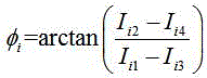
wherein, transient phase distribution corresponding to RGB three wavelength channels; i isijThe intensity distribution of four interference patterns with the phase difference of pi/2 corresponding to each wavelength channel; i = R, G, B; j =1,2,3, 4;
the optical path difference between the reference light and the detection light on each pixel point is obtained by using a multi-wavelength measurement technology, and the formula is as follows:
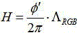
wherein, H is the optical path difference between the reference light and the detection light on each pixel point;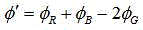 ;ΛRGBis λR、λGAnd λBOf equivalent wavelength, λR、λGAnd λBThe wavelengths of RGB three-color light are respectively;
 ,ΛRGis λRAnd λGOf the equivalent wavelength of ΛGBIs λGAnd λBThe equivalent wavelength of (a) is,
 ,
, ,
, 。
。
as a further improvement of the present invention, the light source includes a first LED light source, a second LED light source and a third LED light source, and the first LED light source, the second LED light source and the third LED light source are respectively used for emitting R, G, B three-color light.
As a further improvement of the present invention, the beam combining assembly includes a first optical fiber, a second optical fiber, a third optical fiber, an optical fiber beam combiner, and a fourth optical fiber, the first LED light source, the second LED light source, and the third LED light source are respectively connected to the optical fiber beam combiner through the first optical fiber, the second optical fiber, and the third optical fiber, and the optical fiber beam combiner couples the three RGB color lights into one beam and enters the fourth optical fiber.
As a further improvement of the present invention, the surface shape detection system further includes a polarizer disposed between the beam combining assembly and the beam expanding system, and the relative light intensity between the detection light and the reference light is adjusted by adjusting the transmission axis direction of the polarizer, so as to improve the contrast of the interference fringes.
As a further improvement of the present invention, the surface shape detection system further includes a collimator, disposed between the beam combining assembly and the polarizer, for collimating a beam of coupled light and then irradiating the collimated beam of coupled light to the polarizer.
As a further improvement of the invention, the surface shape detection system further comprises an imaging lens, which is arranged between the quarter-wave plate and the color polarization camera and is used for converging two circularly polarized light beams with opposite rotation directions to the color polarization camera.
As a further improvement of the present invention, the surface shape detection system further includes:
and the light splitting unit is used for reflecting the light expanded by the beam expanding system to the microscope objective and transmitting the reference light and the detection light emitted from the microscope objective.
As a further improvement of the present invention, the light splitting unit is a light splitting prism.
The invention also provides a surface shape detection method, which is applied to any one of the surface shape detection systems and comprises the following steps:
receiving RGB three-color light emitted by the light source by using the beam combining assembly, and coupling the RGB three-color light into a beam of light;
expanding the coupled beam of light by using the beam expanding system;
converging the light expanded by the beam expanding system by using the microscope objective;
the polarization beam splitter is used for dividing the converged light into reflected s-polarized light and transmitted p-polarized light, the transmitted p-polarized light is used as detection light, and the detection light is reflected back to the polarization beam splitter through an object to be detected; the reflected s-polarized light is used as reference light, and the reference light is reflected back to the polarization beam splitter after passing through the reference reflector arranged on the reflection path; the polarization beam splitter combines the returned detection light and the reference light, and emits the detection light and the reference light after passing through a microscope objective;
converting the reference light and the detection light emitted from the microscope objective into two beams of circularly polarized light with opposite rotation directions by using a quarter wave plate;
shooting the two beams of circularly polarized light with opposite rotation directions by using the color polarization camera, and simultaneously obtaining interference patterns corresponding to the three RGB wavelength channels in four channels of the color polarization camera; wherein, each wavelength channel corresponds to four interference patterns with the phase difference of pi/2;
and calculating to obtain transient phase distribution corresponding to the RGB three wavelength channels by using the calculating module, and obtaining the optical path difference between the reference light and the detection light on each pixel point by using a multi-wavelength measuring technology to obtain the surface shape of the object to be detected.
The invention has the beneficial effects that:
the surface shape detection system and the surface shape detection method have the advantages that RGB tricolor light is coupled into the Miller polarization interference objective lens, the separation and extraction of RGB three wavelength channels are completed by adopting the color polarization camera, and meanwhile, four-step phase shifting with the step length of pi/2 is realized by utilizing interference patterns of four adjacent micro-polaroid arrays in the color polarization camera to each wavelength channel. The system can realize multi-wavelength phase-shift interferometry, increase the dynamic measurement range, can calculate four transient phase-shift interferograms of three RGB wavelength channels by single image acquisition of the color polarization camera, has strong anti-interference capability, and has the advantages of high precision, quick measurement and low cost.
The foregoing description is only an overview of the technical solutions of the present invention, and in order to make the technical means of the present invention more clearly understood, the present invention may be implemented in accordance with the content of the description, and in order to make the above and other objects, features, and advantages of the present invention more clearly understood, the following preferred embodiments are described in detail with reference to the accompanying drawings.
Drawings
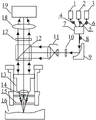
FIG. 1 is a schematic diagram of a surface shape detection system in a preferred embodiment of the present invention.
Description of the labeling: 1. a first LED light source; 2. a second LED light source; 3. a third LED light source; 4. a first optical fiber; 5. a second optical fiber; 6. a third optical fiber; 7. an optical fiber combiner; 8. a fourth optical fiber; 9. a collimator; 10. a polarizing plate; 11. a beam expanding system; 12. a light splitting unit; 13. a microscope objective; 14. a reference mirror; 15. a polarization beam splitter; 16. an object to be tested; 17. a quarter wave plate; 18. an imaging lens; 19. a color polarization camera.
Detailed Description
The present invention is further described below in conjunction with the following figures and specific examples so that those skilled in the art may better understand the present invention and practice it, but the examples are not intended to limit the present invention.
As shown in fig. 1, a preferred embodiment of the present invention discloses a surface shape detection system for detecting a surface shape of an object 16 to be detected, which includes an optical coupling unit, a miller polarization interference unit and a detection calculation unit, wherein the optical coupling unit includes a beam combination component and a beam expansion system 11, the miller polarization interference unit includes a microscope objective 13, a polarization splitting plate 15 and a reference mirror 14, and the detection calculation unit includes a quarter-wave plate 17, a color polarization camera 19 and a calculation module.
The beam combining component receives RGB three-color light emitted by a light source and couples the RGB three-color light into a beam of light;
the beam expanding system 11 expands a beam of coupled light; optionally, the beam expanding system 11 is a beam expander.
The microscope objective 13 is used for converging the light expanded by the beam expanding system 11;
the polarization light-splitting plate 15 is configured to split the converged light into reflected s-polarized light and transmitted p-polarized light, where the transmitted p-polarized light is used as detection light, and the detection light is reflected back to the polarization light-splitting plate 15 through the object 16 to be detected; the reflected s-polarized light is used as reference light, and the reference light is reflected back to the polarization beam splitter 15 after passing through the reference mirror 14 arranged on the reflection path; the polarization beam splitter 15 converges the returned detection light and the reference light, and emits the detection light and the reference light after passing through the microscope objective 13; further, the material and thickness of the glass substrate of the reference mirror 14 are the same as those of the glass substrate of the polarization splitting plate 15 to compensate for the aberration introduced by the glass substrate of the polarization splitting plate 15.
In one embodiment, the microscope objective 13 has a magnification of 4 and a numerical aperture NA of 0.13; the polarization beam splitter 15 corresponds to the maximum transmittance T of the transmitted p-polarized lightPGreater than 82% and maximum transmission T of reflected s-polarized lightSLess than 0.015%, applicable wavelength range of 420-700 nm, and maximum allowable incident half angle of light greater than 20 deg.
The quarter-wave plate 17 is used for changing the reference light and the detection light emitted from the microscope objective lens 13 into two circularly polarized lights with opposite rotation directions; wherein the fast axis direction of the quarter-wave plate 17 forms an angle of 45 ° with the x-axis.
The color polarization camera 19 is used for shooting the two beams of circularly polarized light with opposite rotation directions, and interference patterns respectively corresponding to the three wavelength channels of RGB are obtained simultaneously in the four channels of the color polarization camera 19; wherein, each wavelength channel corresponds to four interference patterns with the phase difference of pi/2. The four channels of the color polarization camera respectively correspond to four adjacent micro-polarizer arrays with the transmission axis angles of 0 degree, 45 degrees, 90 degrees and 135 degrees, and four-step phase shifting with the step length of pi/2 can be realized on the interference pattern of each wavelength channel.
The calculation module is used for calculating the transient phase distribution corresponding to the RGB three wavelength channels respectively by using a four-step phase-shifting algorithm according to the intensity distribution of four interference patterns with the phase difference of pi/2 corresponding to each wavelength channel, and obtaining the optical path difference between the reference light and the detection light on each pixel point by using a multi-wavelength measurement technology so as to obtain the surface shape of the object to be measured 16.
Specifically, the transient phase distribution corresponding to the three RGB wavelengths is calculated by using a four-step phase-shifting algorithm, and the formula is as follows:

wherein, transient phase distribution corresponding to RGB three wavelength channels; i isijThe intensity distribution of four interference patterns with the phase difference of pi/2 corresponding to each wavelength channel; i = R, G, B; j =1,2,3,4, respectively corresponding to the interference patterns with the light transmission axis angles of 0 °, 45 °, 90 °, and 135 °, wherein four directions of four channels of the color polarization camera respectively interfere with each other, and the phase difference between two adjacent interference patterns is pi/2, so as to obtain four interference patterns with the phase difference of pi/2.
The optical path difference between the reference light and the detection light on each pixel point is obtained by using a multi-wavelength measurement technology, and the formula is as follows:

wherein, H is the optical path difference between the reference light and the detection light on each pixel point;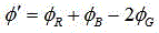 ;ΛRGBis λR、λGAnd λBOf equivalent wavelength λR、λGAnd λBThe wavelengths of RGB three-color light are respectively;
 ,ΛRGis λRAnd λGOf the equivalent wavelength of ΛGBIs λGAnd λBThe equivalent wavelength of (a) is greater than (b),
 ,
, ,
, 。
。
in one embodiment, the light sources include a first LED light source 1, a second LED light source 2 and a third LED light source 3, the first LED light source 1, the second LED light source 2 and the third LED light source 3 are respectively used for emitting R, G, B three color lights, and the wavelengths of R, G, B three color lights are λR、λGAnd λB. Alternatively, λR=625nm,λG=530nm,λB=470nm。
In one embodiment, the beam combining assembly includes a first optical fiber 4, a second optical fiber 5, a third optical fiber 6, an optical fiber beam combiner 7, and a fourth optical fiber 8, the first LED light source 1, the second LED light source 2, and the third LED light source 3 are respectively connected to the optical fiber beam combiner 7 through the first optical fiber 4, the second optical fiber 5, and the third optical fiber 6, and the optical fiber beam combiner 7 couples three color lights of RGB into one beam and enters the fourth optical fiber 8.
In some embodiments, the surface shape detection system further includes a polarizer 10 disposed between the beam combining assembly and the beam expanding system 11, and the relative intensity between the detection light and the reference light is adjusted by adjusting the transmission axis direction of the polarizer 10, so as to improve the contrast of the interference fringes. The contrast of the fringes cannot be accurately measured due to the fact that the test light reflected by the sample with low reflectivity is much weaker than the reference light, and the reference light and the test light can have good contrast by adjusting the direction of the transmission axis of the polaroid 10, so that accurate measurement is achieved.
In one embodiment, the surface shape detecting system further includes a collimator 9 disposed between the beam combining assembly and the polarizer 10, and configured to collimate and irradiate a beam of coupled light onto the polarizer 10.
In some embodiments, the surface shape detection system further includes an imaging lens 18 disposed between the quarter-wave plate 17 and the color polarization camera 19 for converging the two circularly polarized lights with opposite rotation directions to the color polarization camera 19. Meanwhile, the imaging lens 18 may serve as an eyepiece of the microscope objective 13.
In some embodiments, the surface shape detecting system further includes a light splitting unit, configured to reflect the light expanded by the beam expanding system 11 to the microscope objective 13, and transmit the reference light and the detection light emitted from the microscope objective 13. Optionally, the light splitting unit 12 is a light splitting prism. The splitting ratio was 1: 1.
The surface shape detection system and the surface shape detection method realize the four-step phase shift with the step length of pi/2 on the interference pattern of each wavelength channel by coupling RGB tricolor light into the Miller polarization interference objective lens, completing the separation and extraction of RGB three wavelength channels by adopting the color polarization camera, and simultaneously utilizing four adjacent micro-polarizer arrays with the light transmission axis angles of 0 degree, 45 degrees, 90 degrees and 135 degrees in the color polarization camera to realize the four-step phase shift with the step length of pi/2. The system can realize multi-wavelength phase-shift interferometry, increase the dynamic measurement range, can calculate four transient phase-shift interferograms of three RGB wavelength channels by single image acquisition of the color polarization camera, has strong anti-interference capability, and has the advantages of high precision, quick measurement and low cost.
The preferred embodiment of the present invention also discloses a surface shape detection method, which is applied to the surface shape detection system described in the above embodiment, and comprises:
receiving RGB three-color light emitted by the light source by using the beam combining assembly, and coupling the RGB three-color light into a beam of light;
expanding the coupled beam of light by using the beam expanding system 11;
converging the light expanded by the beam expanding system by using the microscope objective 13;
the polarization beam splitter 15 is used for splitting the converged light into reflected s-polarized light and transmitted p-polarized light, the transmitted p-polarized light is used as detection light, and the detection light is reflected back to the polarization beam splitter 15 through the object 16 to be detected; the reflected s-polarized light is used as reference light, and the reference light is reflected back to the polarization beam splitter 15 after passing through the reference mirror 14 arranged on the reflection path; the polarization beam splitter 15 converges the returned detection light and the reference light, and emits the detection light and the reference light after passing through the microscope objective 13;
the reference light and the detection light emitted from the microscope objective 13 are changed into two circularly polarized lights with opposite rotation directions by a quarter wave plate 17;
the two beams of circularly polarized light with opposite rotation directions are shot by the color polarization camera 19, and interferograms respectively corresponding to three wavelength channels of RGB are obtained simultaneously in four channels of the color polarization camera 19; wherein, each wavelength channel corresponds to four interference patterns with the phase difference of pi/2;
and calculating to obtain transient phase distributions corresponding to the three RGB wavelength channels by using the calculation module, and obtaining the optical path difference between the reference light and the detection light on each pixel point by using a multi-wavelength measurement technology to obtain the surface shape of the object to be measured 16.
The surface shape detection method of the preferred embodiment of the present invention is applied to the aforementioned surface shape detection system, and therefore, the specific implementation of the method can be seen in the embodiment section of the surface shape detection system in the foregoing, and therefore, the specific implementation thereof can refer to the description of the corresponding respective embodiment sections, and is not further described herein.
In addition, since the surface shape detection method of the present embodiment is applied to the surface shape detection system, the function thereof corresponds to the function of the system, and is not described herein again.
The above embodiments are merely preferred embodiments for fully illustrating the present invention, and the scope of the present invention is not limited thereto. The equivalent substitution or change made by the technical personnel in the technical field on the basis of the invention is all within the protection scope of the invention. The protection scope of the invention is subject to the claims.
Claims (10)
1. The surface shape detection system is used for detecting the surface shape of an object to be detected, and is characterized by comprising:
the optical coupling unit comprises a beam combination component and a beam expansion system,
the beam combination assembly receives RGB three-color light emitted by a light source and couples the RGB three-color light into a beam of light;
the beam expanding system expands a beam of coupled light;
the Miller polarization interference unit comprises a microscope objective, a polarization beam splitter and a reference reflector,
the microscope objective is used for converging the light expanded by the beam expanding system;
the polarization beam splitter is used for dividing the converged light into reflected s-polarized light and transmitted p-polarized light, the transmitted p-polarized light is used as detection light, and the detection light is reflected back to the polarization beam splitter through an object to be detected; the reflected s-polarized light is used as reference light, and the reference light is reflected back to the polarization beam splitter after passing through the reference reflector arranged on the reflection path; the polarization beam splitter combines the returned detection light and the reference light, and emits the detection light and the reference light after passing through a microscope objective;
a detection calculation unit which comprises a quarter-wave plate, a color polarization camera and a calculation module,
the quarter-wave plate is used for converting the reference light and the detection light emitted from the micro objective lens into two beams of circularly polarized light with opposite rotating directions;
the color polarization camera is used for shooting the two beams of circularly polarized light with opposite rotation directions, and interference patterns respectively corresponding to the three wavelength channels of RGB are obtained simultaneously in four channels of the color polarization camera; wherein, each wavelength channel corresponds to four interference patterns with the phase difference of pi/2;
the calculation module is used for calculating to obtain transient phase distribution corresponding to RGB three wavelength channels respectively by using a four-step phase shift algorithm according to the intensity distribution of four interference patterns with phase difference of pi/2 corresponding to each wavelength channel, and obtaining the optical path difference of reference light and detection light on each pixel point by using a multi-wavelength measurement technology to obtain the surface shape of the object to be measured.
2. The surface shape detection system according to claim 1, wherein the transient phase distributions corresponding to the three RGB wavelengths are calculated by a four-step phase-shifting algorithm, and the formula is as follows:

wherein, transient phase distribution corresponding to RGB three wavelength channels; i isijThe intensity distribution of four interference patterns with the phase difference of pi/2 corresponding to each wavelength channel; i = R, G, B; j =1,2,3, 4;
the optical path difference between the reference light and the detection light on each pixel point is obtained by using a multi-wavelength measurement technology, and the formula is as follows:
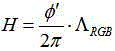
wherein, H is the optical path difference between the reference light and the detection light on each pixel point; ;ΛRGBis λR、λGAnd λBOf equivalent wavelength λR、λGAnd λBThe wavelengths of RGB three-color light are respectively;
 ,ΛRGis λRAnd λGOf the equivalent wavelength of ΛGBIs λGAnd λBThe equivalent wavelength of (a) is,
 ,
, ,
,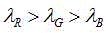 。
。
3. the facial detection system of claim 1, wherein the light source comprises a first LED light source, a second LED light source and a third LED light source, and the first LED light source, the second LED light source and the third LED light source are respectively configured to emit R, G, B three-color light.
4. The surface shape detection system of claim 2, wherein the beam combiner comprises a first optical fiber, a second optical fiber, a third optical fiber, a fiber beam combiner and a fourth optical fiber, the first, second and third LED light sources are respectively connected with the fiber beam combiner through the first, second and third optical fibers, and the fiber beam combiner couples RGB three-color light into one beam and enters the fourth optical fiber.
5. The system of claim 1, wherein the system further comprises a polarizer disposed between the beam combiner and the beam expander, and the relative intensity between the detection light and the reference light is adjusted by adjusting the transmission axis direction of the polarizer to improve the contrast of the interference fringes.
6. The system of claim 5, wherein the system further comprises a collimator disposed between the beam combiner and the polarizer for collimating a beam of coupled light and transmitting the collimated beam of coupled light to the polarizer.
7. The system of claim 1, wherein the system further comprises an imaging lens disposed between the quarter-wave plate and the color polarization camera for converging two circularly polarized lights with opposite handedness to the color polarization camera.
8. The facial detection system of claim 1, further comprising:
and the light splitting unit is used for reflecting the light expanded by the beam expanding system to the microscope objective and transmitting the reference light and the detection light emitted from the microscope objective.
9. The profile testing system as claimed in claim 8, wherein the beam splitting unit is a beam splitting prism.
10. The surface shape detection method applied to the surface shape detection system according to any one of claims 1 to 9, comprising:
receiving RGB three-color light emitted by the light source by using the beam combining assembly, and coupling the RGB three-color light into a beam of light;
expanding the coupled beam of light by using the beam expanding system;
converging the light expanded by the beam expanding system by using the microscope objective;
the polarization beam splitter is used for dividing the converged light into reflected s-polarized light and transmitted p-polarized light, the transmitted p-polarized light is used as detection light, and the detection light is reflected back to the polarization beam splitter through an object to be detected; the reflected s-polarized light is used as reference light, and the reference light is reflected back to the polarization beam splitter after passing through the reference reflector arranged on the reflection path; the polarization beam splitter combines the returned detection light and the reference light, and emits the detection light and the reference light after passing through a microscope objective;
converting the reference light and the detection light emitted from the microscope objective into two beams of circularly polarized light with opposite rotation directions by using a quarter-wave plate;
shooting the two beams of circularly polarized light with opposite rotation directions by using the color polarization camera, and simultaneously obtaining interference patterns corresponding to the three RGB wavelength channels in four channels of the color polarization camera; wherein, each wavelength channel corresponds to four interference patterns with the phase difference of pi/2;
and calculating by using the calculating module to obtain transient phase distributions corresponding to the three RGB wavelength channels, and obtaining the optical path difference between the reference light and the detection light on each pixel point by using a multi-wavelength measuring technology to obtain the surface shape of the object to be measured.
Priority Applications (1)
| Application Number | Priority Date | Filing Date | Title |
|---|---|---|---|
| CN202210263969.2A CN114577111A (en) | 2022-03-17 | 2022-03-17 | Surface shape detection system and detection method |
Applications Claiming Priority (1)
| Application Number | Priority Date | Filing Date | Title |
|---|---|---|---|
| CN202210263969.2A CN114577111A (en) | 2022-03-17 | 2022-03-17 | Surface shape detection system and detection method |
Publications (1)
| Publication Number | Publication Date |
|---|---|
| CN114577111A true CN114577111A (en) | 2022-06-03 |
Family
ID=81779842
Family Applications (1)
| Application Number | Title | Priority Date | Filing Date |
|---|---|---|---|
| CN202210263969.2A Pending CN114577111A (en) | 2022-03-17 | 2022-03-17 | Surface shape detection system and detection method |
Country Status (1)
| Country | Link |
|---|---|
| CN (1) | CN114577111A (en) |
Cited By (1)
| Publication number | Priority date | Publication date | Assignee | Title |
|---|---|---|---|---|
| CN116625229A (en) * | 2023-04-11 | 2023-08-22 | 业成科技(成都)有限公司 | Measuring method of Michelson interferometer and Michelson interferometer |
Citations (3)
| Publication number | Priority date | Publication date | Assignee | Title |
|---|---|---|---|---|
| US5258665A (en) * | 1992-05-12 | 1993-11-02 | National Semiconductor Corporation | AC Miller-Killer circuit for L→Z transitions |
| CN105371752A (en) * | 2015-11-19 | 2016-03-02 | 中国计量学院 | Fringe contrast-adjustable polarization type Miller interferometric device and measuring method |
| CN110186390A (en) * | 2019-05-21 | 2019-08-30 | 中国计量大学 | Compact transient state multi-wavelength phase shift interference device and its measurement method |
-
2022
- 2022-03-17 CN CN202210263969.2A patent/CN114577111A/en active Pending
Patent Citations (3)
| Publication number | Priority date | Publication date | Assignee | Title |
|---|---|---|---|---|
| US5258665A (en) * | 1992-05-12 | 1993-11-02 | National Semiconductor Corporation | AC Miller-Killer circuit for L→Z transitions |
| CN105371752A (en) * | 2015-11-19 | 2016-03-02 | 中国计量学院 | Fringe contrast-adjustable polarization type Miller interferometric device and measuring method |
| CN110186390A (en) * | 2019-05-21 | 2019-08-30 | 中国计量大学 | Compact transient state multi-wavelength phase shift interference device and its measurement method |
Cited By (1)
| Publication number | Priority date | Publication date | Assignee | Title |
|---|---|---|---|---|
| CN116625229A (en) * | 2023-04-11 | 2023-08-22 | 业成科技(成都)有限公司 | Measuring method of Michelson interferometer and Michelson interferometer |
Similar Documents
| Publication | Publication Date | Title |
|---|---|---|
| CN110987817B (en) | Ellipsometer integrating dark field observation based on large-numerical-aperture objective lens and measurement method | |
| CN101788263B (en) | Coaxial Fizeau synchronous phase shifting interferometer capable of adjusting extended light illumination | |
| US7499178B2 (en) | Oblique incidence interferometer | |
| US4948253A (en) | Interferometric surface profiler for spherical surfaces | |
| CN106500589B (en) | A kind of measurement method and device of multi-wavelength tunable microscopic interference | |
| TWI326354B (en) | Method and apparatus for simultaneously acquiring interferograms and method for solving the phase | |
| CN102889853B (en) | Spectral synchronous phase-shift common-path interference microscopic-detection device and detection method | |
| CN108195849A (en) | Position phase defect detecting system and method based on the safe graceful interferometer of short relevant dynamic | |
| CN113587843B (en) | Interferometric confocal measurement system and measurement method | |
| CN206311061U (en) | A kind of measurement apparatus of multi-wavelength tunable micro-interference | |
| CN109975820A (en) | Synchronization polarization phase-shifting focus detection system based on Linnik type interference microscope | |
| CN111207844B (en) | Double-sided multi-plane inclined wavefront interferometer and its detection method | |
| CN109211934A (en) | Based on interference micro- microballoon planar defect detection device and its detection method | |
| CN110095085A (en) | A kind of real-time phase shift interference with common path microscope equipment and method | |
| CN115112045B (en) | Interferometric measurement method based on all-fiber orthogonal polarization optical path matching short coherent light source | |
| CN111929036B (en) | Double Fizeau cavity dynamic short coherence interferometry device and method | |
| CN101319873B (en) | Spatial Phase Shifters for Synchronized Phase-Shifting Interferometers | |
| CN108132026B (en) | Semiconductor mid-infrared visible light dual-wavelength transmission interference test device | |
| CN210242710U (en) | Microstructure morphology measuring device based on dispersion spectrum coding | |
| US12203752B2 (en) | Compact snapshot dual-mode interferometric system | |
| CN115598147B (en) | Device and method for detecting defects on inner and outer surfaces of microspheres based on white light microinterference | |
| CN114459620B (en) | Device and method for generating π phase shift between dual interference channels through a single wave plate | |
| CN114577111A (en) | Surface shape detection system and detection method | |
| CN105277338B (en) | Large-numerical aperture phase shift double needle hole diffraction interferometer and its test method | |
| Wyant | Advances in interferometric metrology |
Legal Events
| Date | Code | Title | Description |
|---|---|---|---|
| PB01 | Publication | ||
| PB01 | Publication | ||
| SE01 | Entry into force of request for substantive examination | ||
| SE01 | Entry into force of request for substantive examination | ||
| RJ01 | Rejection of invention patent application after publication | ||
| RJ01 | Rejection of invention patent application after publication |
Application publication date: 20220603 |