Disclosure of Invention
In view of the various problems of the prior art, the existence and derivation of the judgment by the human eye are various. It is a primary object of the present invention to provide a visual identification system for a motor stator assembly that addresses at least one of the problems of the prior art.
The present invention is directed to solve the problems of the prior art, and a necessary technical means is to provide a visual recognition system for a motor stator assembly, which is used to recognize and detect the number and the position of features of a motor stator assembly located in a detection area.
The image acquisition module is used for acquiring an image of the motor stator component. The visual identification module receives the image of the motor stator assembly, identifies the number of the characteristic pieces according to the specific shape and the specific gray-scale value area in the image, and identifies whether the motor stator assembly meets a qualified condition according to the number of the characteristic pieces and the position of the characteristic pieces. The prompting module is electrically connected with the visual identification module and generates qualified prompt information when the motor stator assembly meets qualified conditions; otherwise, the prompt module generates unqualified prompt information when the motor stator assembly meets an unqualified condition.
Based on the above-mentioned necessary technical means, an accessory technical means derived by the invention is that the visual identification module in the visual identification system of the motor stator assembly comprises a quantity identification unit, the quantity identification unit utilizes a feature comparison data to identify the feature and the quantity of the feature, and the unqualified condition is that the quantity of the feature is different from a qualified quantity.
Based on the above-mentioned necessary technical means, an auxiliary technical means derived from the invention is to make the qualified number of the visual identification systems of the stator assemblies of the motor be three.
Based on the above-mentioned necessary technical means, an accessory technical means derived from the present invention is to make the visual recognition module in the visual recognition system of the motor stator assembly further comprise a distance calculation unit and a distance recognition unit. The distance calculation unit is electrically connected with the number identification unit and used for calculating a plurality of characteristic distances according to the positions of the characteristic pieces. The distance identification unit is electrically connected with the distance calculation unit and used for receiving the characteristic distances and identifying whether each characteristic distance is in one of a first qualified distance range and a second qualified distance range. The qualified condition is that the number of the features is the same as the qualified number, and each feature distance is located in one of a first qualified distance range and a second qualified distance range; the unqualified condition is that the number of the features is the same as the qualified number, and any feature distance is positioned outside the first qualified distance range and the second qualified distance range.
Based on the above-mentioned necessary technical means, an accessory technical means derived by the present invention is that the visual identification module in the visual identification system of the motor stator assembly further comprises a reference point defining unit, the reference point defining unit is electrically connected with the distance calculating unit, a reference point is defined in the motor stator assembly by using a reference point comparison data, and the distance calculating unit calculates the characteristic distance by using each characteristic piece and the reference point.
On the basis of the necessary technical means, an auxiliary technical means derived by the invention is that the visual identification module in the visual identification system of the motor stator assembly further comprises an identification processing unit which is electrically connected with the quantity identification unit and the distance identification unit and is used for generating a qualified signal when the motor stator assembly is identified to meet qualified conditions, so that the prompt module generates qualified prompt information; when the motor stator assembly meets the unqualified condition, an unqualified signal is generated, so that the prompt module generates unqualified prompt information.
Based on the above-mentioned necessary technical means, an accessory technical means derived from the present invention is that the visual identification module in the visual identification system of the motor stator assembly further comprises a storage unit, and the storage unit is electrically connected to the number identification unit and the reference point definition unit for storing the feature comparison data and the reference point comparison data.
Based on the above-mentioned necessary technical means, an accessory technical means derived from the present invention is a visual identification system for a motor stator assembly, further comprising a display module, wherein the display module is electrically connected to the image acquisition module for displaying an image of the motor stator assembly.
The present invention is directed to solve the problems of the prior art, and a necessary technical means is to provide a visual recognition method for a motor stator assembly, which is implemented by using the visual recognition system for a motor stator assembly, and comprises the following steps: acquiring an image of a stator assembly of the motor by using an image acquisition module; identifying the number of the characteristic pieces by using a visual identification module according to the specific shape and the specific gray scale value area in the image, and identifying whether the motor stator assembly meets the qualified conditions or not according to the number of the characteristic pieces and the positions of the characteristic pieces; when the motor stator assembly meets the qualified conditions, qualified prompt information is generated by using a prompt module; and when the motor stator assembly meets the unqualified condition, unqualified prompt information is generated.
Based on the above-mentioned necessary technical means, an accessory technical means derived from the present invention is a step in the visual identification method of the motor stator assembly, further comprising the steps of: identifying whether the number of the features is equal to a qualified number by using a number identification unit of the visual identification module; when the judgment is yes, defining a reference point by using a reference point defining unit of the visual identification module; calculating a characteristic distance between each characteristic element and the datum point by using a distance calculation unit of the visual identification module so as to calculate a plurality of characteristic distances; a distance identification unit of the visual identification module is utilized to identify whether each characteristic distance is located in one of a first qualified distance range and a second qualified distance range.
In view of the above, the visual recognition system and method for a motor stator assembly provided by the invention utilize the image acquisition module, the visual recognition module and the prompt module, compared with the prior art, the visual recognition system and method provided by the invention can utilize the visual recognition module to judge the number and the position of the features of the motor stator assembly, and judge whether the motor stator assembly meets the qualified conditions according to the number and the position, thereby solving the risks existing in human eye judgment and various derived problems. In addition, the prompt module is used for generating qualified prompt information or unqualified prompt information, so that the identification result is more visual, and the accuracy and efficiency of identification are improved.
Drawings
FIG. 1 is a block diagram illustrating a visual identification system for a motor stator assembly according to a preferred embodiment of the present invention;
FIG. 2 is a schematic view of a visual identification system for a motor stator assembly according to a preferred embodiment of the present invention;
FIG. 3 is a top view showing a motor stator assembly;
FIG. 4 is a schematic diagram illustrating a visual identification system of a motor stator assembly according to a preferred embodiment of the present invention generating a fail indication;
FIG. 5 is a top view showing another motor stator assembly;
FIG. 6 is a top view showing yet another motor stator assembly;
FIG. 7 is a schematic diagram illustrating a visual identification system of a motor stator assembly according to a preferred embodiment of the present invention generating a qualified prompt; and
fig. 8 is a flow chart illustrating a method for visually identifying a stator assembly of a motor according to a preferred embodiment of the invention.
Description of the reference numerals
Visual identification system for motor stator assembly
Image acquisition module
12 visual recognition module
121 number identification unit
122 distance calculation unit
123 distance identification unit
124 reference point defining unit
125 recognition processing unit
126 memory cell
13 prompt module
14 bearing platform
15 display module
16 support piece
A, detection area
L1 first light Beam
L2 second light Beam
Characteristic distances of L1b, L2b, L3b, L4b, L5b, L6b, L1c, L2c, L3c, L4c, L5c and L6c
R1b, R2b, R3b, R1c, R2c, R3c are references
Sa, Sb, Sc motor stator assembly
S1a, S2a, S1b, S2b, S3b, S1c, S2c, S3c, features
Detailed Description
The following describes in more detail embodiments of the present invention with reference to the schematic drawings. Advantages and features of the present invention will become apparent from the following description and claims. It is to be noted that the drawings are in a very simplified form and are not to precise scale, which is merely for the purpose of facilitating and distinctly claiming the embodiments of the present invention.
Referring to fig. 1 to 7, fig. 1 is a block diagram illustrating a visual recognition system of a stator assembly of a motor according to a preferred embodiment of the present invention; FIG. 2 is a schematic view of a visual identification system for a motor stator assembly according to a preferred embodiment of the present invention; FIG. 3 is a top view showing a motor stator assembly; FIG. 4 is a schematic diagram illustrating a visual identification system of a motor stator assembly according to a preferred embodiment of the present invention generating a fail indication; FIG. 5 is a top view showing another motor stator assembly; FIG. 6 is a top view showing yet another motor stator assembly; fig. 7 is a schematic diagram illustrating the qualification prompt generated by the visual identification system of the motor stator assembly according to the preferred embodiment of the invention. As shown in the figure, a vision recognition system 1 of a motor stator assembly includes an image acquisition module 11, a vision recognition module 12, a prompt module 13, a carrying platform 14, a display module 15 and a supporting member 16.
The visual recognition system 1 of the motor stator assembly is used for recognizing the number and the positions of the features of the motor stator assembly, wherein the motor stator assembly is positioned in a detection area A of the bearing platform 14.
The image acquisition module 11 is used for acquiring an image of the motor stator assembly. In the present embodiment, the image capturing module 11 is fixed on the supporting member 16 and is disposed corresponding to the detection area a.
The vision recognition module 12 receives the image of the motor stator assembly and recognizes the number of features according to the specific shape and the specific gray scale value region in the image. Then, the vision recognition module 12 recognizes whether the motor stator assembly satisfies a qualified condition according to the number of the features and the positions of the features. In the present embodiment, the visual recognition module 12 includes a number recognition unit 121, a distance calculation unit 122, a distance recognition unit 123, a reference point defining unit 124, a recognition processing unit 125, and a storage unit 126.
The prompting module 13 is electrically connected with the visual identification module 12, and identifies that the motor stator assembly meets the qualified conditions in the visual identification module 12 to generate qualified prompt information; otherwise, when the motor stator assembly meets a disqualification condition, a disqualification prompt message is generated.
To further explain, a motor stator assembly Sa is placed in the detection area a, as shown in fig. 2, the image acquisition module 11 acquires an image of the motor stator assembly Sa, which is directly shown by a top view of the motor stator assembly Sa, as shown in fig. 3.
The quantity identification unit 121 identifies the features S1a, S2a of the motor stator assembly Sa by using a feature comparison data, wherein the feature comparison data usually includes a specific shape, a specific gray scale value, a specific color, and the like. Therefore, the number recognition unit 121 recognizes that the number of features of the motor stator assembly Sa is two (features S1a, S2 a). In this embodiment, the qualified number is three, and the rejected condition is that the number of the features is different from the qualified number. Therefore, the motor stator module Sa satisfies the fail condition, and the identification processing unit 125 generates a fail signal, so that the prompt module 13 generates fail prompt information. As shown in fig. 4, the prompt module 13 generates a first light beam L1, which is usually a red light, to indicate that the motor stator assembly Sa satisfies the failure condition, which is a defective product.
When the vision recognition system 1 of the motor stator assembly detects a motor stator assembly Sb, the image obtaining module 11 also obtains an image of the motor stator assembly Sb, as shown in fig. 5. The number recognition unit 121 recognizes the features S1b, S2b, S3b of the motor stator assembly Sb, and thus the number of the features of the motor stator assembly Sb is three, which is qualified.
Then, the distance calculating unit 122 calculates a plurality of feature distances using the features S1b, S2b, S3 b. In the present embodiment, the reference point defining unit 124 defines a reference point R1b by using a reference point comparison data, and the distance calculating unit 122 calculates characteristic distances L1b, L2b, and L3b between the characteristic elements S1b, S2b, and S3b and the reference point R1b, respectively. The storage unit 126 stores the reference point comparison data and the feature comparison data.
The distance recognition unit 123 is configured to receive the feature distances L1b, L2b, and L3b, and recognize whether the feature distances L1b, L2b, and L3b are within a first qualified distance range or a second qualified distance range. In this case, the qualification condition is that the number of features is the same as the qualification number and each feature distance must be within a first qualification distance range or within a second qualification distance range. And otherwise, the unqualified condition is that the number of the features is the same as the qualified number, and any feature distance is positioned outside the first qualified distance range and the second qualified distance range.
In this embodiment, the first acceptable distance range is 55 to 85, and the second acceptable distance range is 128 to 140, since the image determination is used, the unit is a pixel. Here, the feature distance L2b is neither within the first acceptable distance range nor within the second acceptable distance range. Therefore, the motor stator assembly Sb still satisfies the fail condition, and the prompt module 13 still generates fail prompt information.
It should be noted that, the reference point defining unit 124 may also define a reference point R2b and calculate the characteristic distances L4b, L5b, and L6b, but the characteristic distance L5b is still outside the first acceptable distance range and the second acceptable distance range, so the motor stator assembly Sb still satisfies the unqualified condition. Similarly, if the reference point defining unit 124 defines a reference point R3b, the characteristic distance between the reference point R3b and the characteristic element S2b is still outside the first acceptable distance range and the second acceptable distance range, so that the motor stator assembly Sb meets the fail condition. Therefore, the reference point defining unit 124 does not affect the recognition result regardless of which reference point is defined. Briefly, the reason that the motor stator assembly Sb will meet the fail condition is the location of feature S2 b.
When the vision recognition system 1 of the motor stator assembly detects a motor stator assembly Sc, the image obtaining module 11 also obtains an image of the motor stator assembly Sc, as shown in fig. 6. The number recognition unit 121 recognizes the features S1c, S2c, S3c of the motor stator assembly Sc, and thus the number of the features of the motor stator assembly Sc is three, which is qualified.
Then, the distance calculating unit 122 calculates a plurality of feature distances using the features S1c, S2c, S3 c. In the present embodiment, the datum defining unit 124 defines a datum R1c, and the distance calculating unit 122 calculates the characteristic distances L1c, L2c, and L3c between the features S1c, S2c, and S3c and the datum R1c, respectively. The distance identifying unit 123 identifies whether the feature distances L1c, L2c, L3c are within the first qualified distance range or the second qualified distance range.
More specifically, the feature distances L1c, L2c will be within a first range of acceptable distances, and the feature distance L3c will be within a second range of acceptable distances. Therefore, the motor stator assembly Sc meets the qualification requirement, and the identification processing unit 125 generates a qualification signal, so that the prompt module 13 generates a qualification prompt message. As shown in fig. 7, the prompt module 13 generates a second light beam L2, usually green light, to indicate that the motor stator assembly Sc meets the acceptable condition and is a good product.
In addition, the reference point defining unit 124 may also define a reference point R2c, and calculate the characteristic distances L4c, L5c, and L6c, wherein the characteristic distances L4c and L6c are within a first acceptable distance range, and the characteristic distance L5c is within a second acceptable distance range, so that the motor stator assembly Sc still satisfies the acceptable condition. Similarly, if the reference point definition unit 124 defines the reference point R3c, the same recognition result is obtained. Further, the feature distances are not only within the first acceptable distance range or the second acceptable distance range, but also within the first acceptable distance range and the remaining one within the second acceptable distance range.
In this embodiment, the display module 15 can be used to display the image of the motor stator assembly. Preferably, the display module 15 is electrically connected to the identification processing unit 125, and correspondingly displays an unqualified display message when the identification processing unit 125 generates the unqualified signal; and correspondingly displays a qualified display message when the identification processing unit 125 generates the qualified signal. The qualified display information and the unqualified display information are similar to the qualified prompt information and the unqualified prompt information, and the qualified display information and the unqualified display information can be characters (PASS or FAIL), colors (green or red) or other display information capable of indicating the qualification and the unqualified.
In other embodiments of the present invention, the distance calculating unit 122 may directly calculate the characteristic distance, for example, the distance between the characteristics, by using the characteristics without defining the reference point, so as to determine whether the motor stator assembly satisfies the qualified condition.
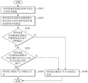
Finally, please refer to fig. 1 to 8, wherein fig. 8 is a flowchart illustrating a visual identification method for a stator assembly of a motor according to a preferred embodiment of the present invention. As shown, a method for visually recognizing a motor stator assembly includes the following steps S101 to S106, wherein the method for visually recognizing a motor stator assembly can be implemented by using the visual recognition system 1 of a motor stator assembly shown in fig. 1.
Step S101: and acquiring an image of the stator assembly of the motor by using an image acquisition module.
Step S101 acquires an image shown in fig. 3, 5, and 6 by using the image acquisition module 11 shown in fig. 1.
Step S102: and identifying the number of the characteristic parts by utilizing a visual identification module according to the specific shape and the specific gray-scale value in the image.
Step S103: identifying, with the visual identification module, whether the number of features is equal to the qualified number.
Steps S102 and S103 identify the features in fig. 3, 5, and 6 by using the visual recognition module 12 in fig. 1, and determine whether the number of features is equal to the qualified number.
Step S104: and identifying whether the motor stator assembly meets qualified conditions or not by using the visual identification module according to the position of the feature.
Step S104 is performed by using the visual recognition module 12 in fig. 1, and the qualified condition may be, for example, the qualified quantity, whether the feature distance is within the first qualified distance range, the second qualified distance range, or the like.
Step S105: and generating qualified prompt information by utilizing a prompt module.
Step S106: and generating unqualified prompt information by using a prompt module.
Steps S105 and S106 generate the pass indication information (the second light beam L2) as in fig. 7 or the fail indication information (the first light beam L1) as in fig. 4 using the indication module 13 as in fig. 1.
In summary, the visual recognition system and method for a motor stator assembly provided by the present invention utilize the image acquisition module, the visual recognition module and the prompt module, compared with the prior art, the present invention can utilize the visual recognition module to determine the number and the position of the features of the motor stator assembly, and accordingly determine whether the motor stator assembly meets the qualified conditions, thereby solving the risks and the derived problems of human eyes. In addition, the prompt module is used for generating qualified prompt information or unqualified prompt information, so that the identification result is more visual, and the accuracy and efficiency of identification are improved.
The foregoing detailed description of the preferred embodiments is intended to more clearly illustrate the features and spirit of the present invention, and not to limit the scope of the invention by the preferred embodiments disclosed above. On the contrary, it is intended to cover various modifications and equivalent arrangements included within the scope of the appended claims.