CN114494129B - Contrast enhancement method for surface slight deformation defect - Google Patents
Contrast enhancement method for surface slight deformation defect Download PDFInfo
- Publication number
- CN114494129B CN114494129B CN202111594118.8A CN202111594118A CN114494129B CN 114494129 B CN114494129 B CN 114494129B CN 202111594118 A CN202111594118 A CN 202111594118A CN 114494129 B CN114494129 B CN 114494129B
- Authority
- CN
- China
- Prior art keywords
- light
- bright
- edge
- inspected
- dark
- Prior art date
- Legal status (The legal status is an assumption and is not a legal conclusion. Google has not performed a legal analysis and makes no representation as to the accuracy of the status listed.)
- Active
Links
Images


Classifications
-
- G—PHYSICS
- G06—COMPUTING OR CALCULATING; COUNTING
- G06T—IMAGE DATA PROCESSING OR GENERATION, IN GENERAL
- G06T7/00—Image analysis
- G06T7/0002—Inspection of images, e.g. flaw detection
- G06T7/0004—Industrial image inspection
-
- G—PHYSICS
- G01—MEASURING; TESTING
- G01B—MEASURING LENGTH, THICKNESS OR SIMILAR LINEAR DIMENSIONS; MEASURING ANGLES; MEASURING AREAS; MEASURING IRREGULARITIES OF SURFACES OR CONTOURS
- G01B11/00—Measuring arrangements characterised by the use of optical techniques
- G01B11/16—Measuring arrangements characterised by the use of optical techniques for measuring the deformation in a solid, e.g. optical strain gauge
-
- G—PHYSICS
- G06—COMPUTING OR CALCULATING; COUNTING
- G06Q—INFORMATION AND COMMUNICATION TECHNOLOGY [ICT] SPECIALLY ADAPTED FOR ADMINISTRATIVE, COMMERCIAL, FINANCIAL, MANAGERIAL OR SUPERVISORY PURPOSES; SYSTEMS OR METHODS SPECIALLY ADAPTED FOR ADMINISTRATIVE, COMMERCIAL, FINANCIAL, MANAGERIAL OR SUPERVISORY PURPOSES, NOT OTHERWISE PROVIDED FOR
- G06Q10/00—Administration; Management
- G06Q10/06—Resources, workflows, human or project management; Enterprise or organisation planning; Enterprise or organisation modelling
- G06Q10/063—Operations research, analysis or management
- G06Q10/0639—Performance analysis of employees; Performance analysis of enterprise or organisation operations
- G06Q10/06395—Quality analysis or management
-
- G—PHYSICS
- G06—COMPUTING OR CALCULATING; COUNTING
- G06T—IMAGE DATA PROCESSING OR GENERATION, IN GENERAL
- G06T5/00—Image enhancement or restoration
- G06T5/50—Image enhancement or restoration using two or more images, e.g. averaging or subtraction
-
- G—PHYSICS
- G06—COMPUTING OR CALCULATING; COUNTING
- G06T—IMAGE DATA PROCESSING OR GENERATION, IN GENERAL
- G06T2207/00—Indexing scheme for image analysis or image enhancement
- G06T2207/20—Special algorithmic details
- G06T2207/20212—Image combination
- G06T2207/20221—Image fusion; Image merging
Landscapes
- Engineering & Computer Science (AREA)
- Business, Economics & Management (AREA)
- Human Resources & Organizations (AREA)
- General Physics & Mathematics (AREA)
- Physics & Mathematics (AREA)
- Theoretical Computer Science (AREA)
- Strategic Management (AREA)
- Entrepreneurship & Innovation (AREA)
- Quality & Reliability (AREA)
- Economics (AREA)
- Educational Administration (AREA)
- Development Economics (AREA)
- Game Theory and Decision Science (AREA)
- Marketing (AREA)
- Operations Research (AREA)
- Tourism & Hospitality (AREA)
- General Business, Economics & Management (AREA)
- Computer Vision & Pattern Recognition (AREA)
- Investigating Materials By The Use Of Optical Means Adapted For Particular Applications (AREA)
Abstract
Description
相关申请related application
本申请请求2021年12月14日提交的名称为“一种工件表面缺陷检测方法、装置及存储介质”、申请号为202111527576.X的中国专利申请的权益和优先权,由此以引用方式全部并入本文中。This application claims the rights and priority of the Chinese patent application entitled "A Method, Device and Storage Medium for Surface Defect Detection of Workpieces" filed on December 14, 2021, with application number 202111527576.X, which is hereby incorporated by reference in its entirety incorporated into this article.
技术领域technical field
本发明涉及机器视觉和数字图像处理技术领域,尤其是指一种表面轻微形变缺陷对比度增强方法。The invention relates to the technical fields of machine vision and digital image processing, in particular to a contrast enhancement method for slight surface deformation defects.
背景技术Background technique
工业生产中对产品质量把关日趋严格,企业对一个强大的表面缺陷检测系统的需求也越来越迫切。当前很大一部分企业依旧采用传统的人工目检法,通过有经验的工人对产品表面逐一观察进行表面检测,该方法存在着以下弊端:效率低、准确性不高、人工成本高以及受工人经验的主观影响大。鉴于人工检查存在诸多难以克服的弊端,以机器视觉为主导的自动化表面缺陷检测由于可以减少各方面成本、提升检测的效率和准确率进而提升产品出口质量,正在成为当前主流的检测手段,受到了越来越多行业的青睐。The quality control of products in industrial production is becoming increasingly strict, and the demand for a powerful surface defect detection system is becoming more and more urgent. At present, a large number of enterprises still use the traditional manual visual inspection method, and the surface inspection is carried out by experienced workers observing the product surface one by one. The subjective influence is large. In view of the many insurmountable disadvantages of manual inspection, automatic surface defect inspection dominated by machine vision is becoming the current mainstream inspection method because it can reduce costs in all aspects, improve the efficiency and accuracy of inspection, and improve the quality of product exports. More and more industries of all ages.
现阶段基于机器视觉的表面缺陷检测主要通过工业相机采集待测物表面的图像,通过图像处理技术分析待测物表面的灰度、纹理、颜色等信息,判断是否存在缺陷。现有的表面检测技术已经能够很好地应用于工业在线检测中较为明显的缺陷;对于表面微小的形变缺陷,例如钢板的轻微凹痕这类缺陷目前是使用结构光作为光源,通过分析条纹光的条纹弯曲程度来检测缺陷,然而这种方法不能完整获取缺陷的信息,影响对缺陷的后续分析,且凹点类缺陷对条纹的弯曲几乎没有影响,因此检测效果不理想。At this stage, surface defect detection based on machine vision mainly collects images of the surface of the object to be tested through industrial cameras, and analyzes the grayscale, texture, color and other information of the surface of the object to be tested through image processing technology to determine whether there are defects. Existing surface detection technology has been well applied to obvious defects in industrial online detection; for small deformation defects on the surface, such as slight dents on steel plates, structured light is currently used as the light source, and by analyzing the stripe light However, this method cannot completely obtain defect information, which affects the subsequent analysis of defects, and pit defects have little effect on the bending of stripes, so the detection effect is not ideal.
表面轻微形变缺陷在均匀光下对比度低且没有明显边缘,成像的成效较低,而在条纹光下无法完整获取缺陷信息,因此在工业检测中如何采集到这类缺陷完整清晰的图像是一个难点。Slightly deformed defects on the surface have low contrast and no obvious edges under uniform light, and the imaging effect is low, and the defect information cannot be completely obtained under striped light. Therefore, how to collect complete and clear images of such defects in industrial inspection is a difficult point .
综上所述可以看出,如何提供一种能够增强表面轻微形变缺陷对比度方法是目前有待解决的问题。From the above, it can be seen that how to provide a method that can enhance the contrast of slightly deformed defects on the surface is a problem to be solved at present.
发明内容Contents of the invention
为此,本发明的目的是提供一种表面轻微形变缺陷对比度增强方法,以解决现有技术不能完整获取缺陷信息,对轻微形变检测不理想的问题。为解决上述技术问题,本发明提供一种表面轻微形变缺陷对比度增强方法,包括:设置表面轻微形变缺陷对比度增强装置;Therefore, the object of the present invention is to provide a method for enhancing the contrast of slightly deformed defects on the surface, so as to solve the problem that the prior art cannot obtain complete defect information and is not ideal for slightly deformed detection. In order to solve the above-mentioned technical problems, the present invention provides a method for enhancing the contrast of slightly deformed defects on the surface, including: setting a device for enhancing the contrast of slightly deformed defects on the surface;
提供照明光源,所述照明光源为包含亮暗区间可移动的组合光源,其中靠近暗区的亮区边缘区域构成了该组合光源的边缘光;Provide an illumination source, the illumination source is a movable combination light source including bright and dark areas, wherein the edge area of the bright area close to the dark area constitutes the edge light of the combined light source;
以所述照明光源向待检表面照射,并向一个方向逐步移动所述照明光源,以确保所述照明光源的边缘光覆盖整个所述待检表面;irradiating the surface to be inspected with the illumination source, and gradually moving the illumination source in one direction to ensure that the edge light of the illumination source covers the entire surface to be inspected;
采集移动过程中所述待检表面的多张反射光线图;Collecting multiple reflected light images of the surface to be inspected during the movement;
将所述多张反射光线图去除亮背景并进行图像合成,得到目标合成图像。优选地,所述照明光源为条纹光。Remove the bright background from the multiple reflected light images and perform image synthesis to obtain a target composite image. Preferably, the illumination light source is stripe light.
优选地,所述边缘光采用条纹光最大亮度的14%~75%部分,即被检表面亮暗分界处靠暗区宽度为Wedge的区域,宽度Wedge的选取可依据被检表面不同位置的灰度值比例进行计算,也可根据缺陷的实际成像效果判断。Preferably, the edge light adopts 14% to 75% of the maximum brightness of the streak light, that is, the area where the width of the dark area near the bright-dark boundary of the inspected surface is W edge , and the selection of the width W edge can be based on different positions of the inspected surface It can also be calculated according to the actual imaging effect of the defect.
优选地,所述采集移动过程中所述待检表面的多张反射光线图包括:Preferably, the plurality of reflected ray images of the surface to be inspected during the collection movement include:
采集所述照明光源以步长为Wedge的移动过程中所述待检表面的k张反射光线图;Collecting k pieces of reflected light diagrams of the surface to be inspected during the movement of the illumination source with a step size of W edge ;
其中k的选取依据以下公式确定:The selection of k is determined according to the following formula:
k=max(Wdark/Wedge-2,Wbright/Wedge)+1k=max(W dark /W edge -2,W bright /W edge )+1
Wdark为暗条纹宽度,Wbright为明条纹宽度,Wedge的选取可依据所述待检表面不同位置的灰度值比例进行计算,也可根据缺陷的实际成像效果判断,所述暗条纹宽度Wdark=2*Wedge时,暗条纹区域均为边缘光检测区域,k=Wbright/Wedge+1,则依据所述明条纹宽度Wbright选择最小扫描周期,以确保能够覆盖被检区域。W dark is the width of dark stripes, and W bright is the width of bright stripes. The selection of W edge can be calculated according to the gray value ratio of different positions on the surface to be inspected, or can be judged according to the actual imaging effect of the defect. The dark stripe width When W dark = 2*W edge , the dark fringe area is the edge light detection area, k=W bright /W edge +1, then select the minimum scanning period according to the bright fringe width W bright to ensure that the detected area can be covered .
优选地,所述将所述多张反射光线图去除亮背景并进行图像合成,得到目标合成图像包括:Preferably, removing the bright background from the multiple reflected light images and performing image synthesis to obtain the target composite image includes:
将所述多张反射光线图分别转换为多个图像信号并传送给计算机;Converting the multiple reflected light maps into multiple image signals and sending them to the computer;
利用局部最大差值法对输入的所述多张反射光线图的多个图像信号分别进行膨胀腐蚀操作来确定指定邻域附近的最大值和最小值,得到多张膨胀腐蚀图像;Using the local maximum difference method to perform dilation and corrosion operations on multiple image signals of the multiple input reflected light maps to determine the maximum value and minimum value near the specified neighborhood, and obtain multiple dilation and corrosion images;
对所述多张膨胀腐蚀图像进行线性组合,得到所述多张无条纹干扰图像;Linearly combining the multiple expansion and erosion images to obtain the multiple streak-free images;
取所述多张无条纹干扰图像的图像信息中对应位置灰度的平均值作为所述目标合成图像的灰度值;Taking the average value of the grayscale of corresponding positions in the image information of the plurality of streak-free images as the grayscale value of the target composite image;
对所述目标合成图像的灰度值进行比例调整得到所述目标合成图像。The gray scale value of the target composite image is proportionally adjusted to obtain the target composite image.
本发明所提供的一种表面轻微形变缺陷对比度增强方法,包括:设置表面轻微形变缺陷对比度增强装置,提供照明光源,所述照明光源为包含亮暗区间可移动的组合光源,其中靠近暗区的亮区边缘区域构成了该组合光源的边缘光,以所述照明光源向待检表面照射,并向一个方向逐步移动所述照明光源,以确保所述照明光源的边缘光覆盖整个所述待检表面,如果所述待检表面无缺陷,光线都在表面上镜面反射,如果所述待检表面存在缺陷,部分光线发散,由于射入缺陷的光线占总光线的比重较大,周围光线对缺陷成像的干扰较小,实现了所述待检表面轻微形变缺陷对比度的增强;将所述多张反射光线图去除亮背景并进行图像合成,得到目标合成图像,从算法上进一步增强了表面轻微形变缺陷的对比度。本发明所提供的一种表面轻微形变缺陷对比度增强方法,利用照明光源的边缘光照射待检表面,增强了表面轻微形变的对比度,并将采集到的光线图片去除亮背景并合成,进一步增强了表面轻微形变的对比度,通过对比度增强可以更好的获取图像信息,检测缺陷。A method for enhancing the contrast of slight surface deformation defects provided by the present invention includes: setting up a device for enhancing the contrast of slight surface deformation defects, and providing an illumination source. The illumination source is a movable combined light source including bright and dark areas. The edge area of the bright area constitutes the edge light of the combined light source, irradiates the surface to be inspected with the illumination light source, and gradually moves the illumination light source in one direction to ensure that the edge light of the illumination light source covers the entire described object to be inspected If there is no defect on the surface to be inspected, the light will be specularly reflected on the surface. If there is a defect on the surface to be inspected, part of the light will diverge. Since the light entering the defect accounts for a large proportion of the total light, the surrounding light will have a large impact on the defect. The interference of imaging is small, and the contrast of the slight deformation defect on the surface to be inspected is enhanced; the bright background is removed from the multiple reflected light images and image synthesis is performed to obtain the target composite image, which further enhances the slight deformation of the surface from the algorithm The contrast of defects. The method for enhancing the contrast of a slightly deformed surface defect provided by the present invention utilizes the marginal light of the illumination source to irradiate the surface to be inspected to enhance the contrast of the slightly deformed surface, and removes the bright background from the collected light pictures and synthesizes them to further enhance the The contrast of the slightly deformed surface can better obtain image information and detect defects through contrast enhancement.
附图说明Description of drawings
为了更清楚的说明本发明实施例或现有技术的技术方案,下面将对实施例或现有技术描述中所需要使用的附图作简单的介绍,显而易见地,下面描述中的附图仅仅是本发明的一些实施例,对于本领域普通技术人员来讲,在不付出创造性劳动的前提下,还可以根据这些附图获得其他的附图。In order to more clearly illustrate the embodiments of the present invention or the technical solutions of the prior art, the following will briefly introduce the accompanying drawings that need to be used in the description of the embodiments or the prior art. Obviously, the accompanying drawings in the following description are only For some embodiments of the present invention, those skilled in the art can also obtain other drawings based on these drawings without creative work.
图1为本发明所提供的表面轻微形变缺陷对比度增强方法的一种具体实施例的流程图;Fig. 1 is a flow chart of a specific embodiment of the method for enhancing the contrast of slightly deformed defects on the surface provided by the present invention;
图2为边缘光示意图;Figure 2 is a schematic diagram of edge light;
图3为条纹光源示意图;Figure 3 is a schematic diagram of a striped light source;
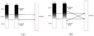
图4为亮条纹边缘缺陷成像示意图;Figure 4 is a schematic diagram of bright stripe edge defect imaging;
图5为表面轻微形变缺陷的原理示意图;Figure 5 is a schematic diagram of the principle of a slight deformation defect on the surface;
图6为实施案例提供的缺陷检测装置示意图;Figure 6 is a schematic diagram of the defect detection device provided in the implementation case;
图7为条纹光移动示意图;Fig. 7 is a schematic diagram of stripe light movement;
图8为钢板表面轻微凹痕成像示意图;Figure 8 is a schematic diagram of imaging of slight dents on the surface of the steel plate;
图9为条纹光下表面轻微缺陷成像示意图;Figure 9 is a schematic diagram of imaging of slight surface defects under streaked light;
图10为合成图像示意图;Figure 10 is a schematic diagram of a synthetic image;
图11为本发明实施例提供的一种表面轻微形变缺陷对比度增强的装置的结构框图。Fig. 11 is a structural block diagram of a device for enhancing the contrast of a slight surface deformation defect provided by an embodiment of the present invention.
具体实施方式Detailed ways
本发明的核心是提供一种表面轻微形变缺陷对比度增强方法,增强了表面轻微形变缺陷的对比度。The core of the invention is to provide a method for enhancing the contrast of slightly deformed defects on the surface, which enhances the contrast of slightly deformed defects on the surface.
为了使本技术领域的人员更好地理解本发明方案,下面结合附图和具体实施方式对本发明作进一步的详细说明。显然,所描述的实施例仅仅是本发明一部分实施例,而不是全部的实施例。基于本发明中的实施例,本领域普通技术人员在没有做出创造性劳动前提下所获得的所有其他实施例,都属于本发明保护的范围。In order to enable those skilled in the art to better understand the solution of the present invention, the present invention will be further described in detail below in conjunction with the accompanying drawings and specific embodiments. Apparently, the described embodiments are only some of the embodiments of the present invention, but not all of them. Based on the embodiments of the present invention, all other embodiments obtained by persons of ordinary skill in the art without making creative efforts belong to the protection scope of the present invention.
请参考图1,图1为本发明所提供的表面轻微形变缺陷对比度增强方法的一种具体实施例的流程图;具体操作步骤如下:Please refer to Fig. 1, Fig. 1 is a flow chart of a specific embodiment of the contrast enhancement method for surface slight deformation defects provided by the present invention; the specific operation steps are as follows:
步骤S101:设置表面轻微形变缺陷对比度增强装置;Step S101: setting a contrast enhancement device for slight surface deformation defects;
步骤S102:以照明光源向待检表面照射,并向一个方向逐步移动所述照明光源,以确保所述照明光源的边缘光覆盖整个所述待检表面;Step S102: illuminating the surface to be inspected with an illumination source, and gradually moving the illumination source in one direction to ensure that the edge light of the illumination source covers the entire surface to be inspected;
步骤S103:采集移动过程中所述待检表面的多张反射光线图;Step S103: collecting multiple reflected light images of the surface to be inspected during the movement;
步骤S104:将所述多张反射光线图去除亮背景并进行图像合成,得到目标合成图像。Step S104: Remove the bright background from the multiple reflected light images and perform image synthesis to obtain a target composite image.
本发明所提供的一种表面轻微形变缺陷对比度增强方法,包括:设置表面轻微形变缺陷对比度增强装置,提供照明光源,所述照明光源为包含亮暗区间可移动的组合光源,其中靠近暗区的亮区边缘区域构成了该组合光源的边缘光,以所述照明光源向待检表面照射,并向一个方向逐步移动所述照明光源,以确保所述照明光源的边缘光覆盖整个所述待检表面,如果所述待检表面无缺陷,光线都在表面上镜面反射,如果所述待检表面存在缺陷,部分光线发散,由于射入缺陷的光线占总光线的比重较大,周围光线对缺陷成像的干扰较小,实现了所述待检表面轻微形变缺陷对比度的增强;将所述多张反射光线图去除亮背景并进行图像合成,得到目标合成图像,从算法上进一步增强了表面轻微形变缺陷的对比度。本发明所提供的一种表面轻微形变缺陷对比度增强方法,利用照明光源的边缘光照射待检表面,增强了表面轻微形变的对比度,并将采集到的光线图片去除亮背景并合成,进一步增强了表面轻微形变的对比度。A method for enhancing the contrast of slight surface deformation defects provided by the present invention includes: setting up a device for enhancing the contrast of slight surface deformation defects, and providing an illumination source. The illumination source is a movable combined light source including bright and dark areas. The edge area of the bright area constitutes the edge light of the combined light source, irradiates the surface to be inspected with the illumination light source, and gradually moves the illumination light source in one direction to ensure that the edge light of the illumination light source covers the entire described object to be inspected If there is no defect on the surface to be inspected, the light will be specularly reflected on the surface. If there is a defect on the surface to be inspected, part of the light will diverge. Since the light entering the defect accounts for a large proportion of the total light, the surrounding light will have a large impact on the defect. The interference of imaging is small, and the contrast of the slight deformation defect on the surface to be inspected is enhanced; the bright background is removed from the multiple reflected light images and image synthesis is performed to obtain the target composite image, which further enhances the slight deformation of the surface from the algorithm The contrast of defects. The method for enhancing the contrast of a slightly deformed surface defect provided by the present invention utilizes the marginal light of the illumination source to irradiate the surface to be inspected to enhance the contrast of the slightly deformed surface, and removes the bright background from the collected light pictures and synthesizes them to further enhance the Contrast of slightly deformed surfaces.
基于上述实施例,本实施例以钢板为待检表面对以上流程进行进一步说明,具体步骤如下:Based on the above-mentioned embodiment, this embodiment takes the steel plate as the surface to be inspected to further illustrate the above process, and the specific steps are as follows:
步骤S201:设置表面轻微形变缺陷对比度增强装置;Step S201: setting a contrast enhancement device for slight surface deformation defects;
步骤S202:以照明光源向待检表面照射,并向一个方向逐步移动所述照明光源,以确保所述照明光源的边缘光覆盖整个所述待检表面;Step S202: illuminating the surface to be inspected with an illumination source, and gradually moving the illumination source in one direction to ensure that the edge light of the illumination source covers the entire surface to be inspected;
所述照明光源为包含亮暗区间可移动的组合光源,其中靠近暗区的亮区边缘区域构成了该组合光源的边缘光,所述边缘光采用条纹光最大亮度的14%~75%部分,即被检表面亮暗分界处靠暗区宽度为Wedge的区域,宽度Wedge的选取可依据被检表面不同位置的灰度值比例进行计算,也可根据缺陷的实际成像效果判断,请参考图2,图2为边缘光示意图;The illumination source is a movable combined light source including bright and dark areas, wherein the edge area of the bright area close to the dark area constitutes the edge light of the combined light source, and the edge light adopts 14% to 75% of the maximum brightness of the stripe light, That is, the area where the width of the dark area near the bright-dark boundary of the inspected surface is W edge , the selection of the width W edge can be calculated based on the gray value ratio of different positions on the inspected surface, or can be judged according to the actual imaging effect of the defect, please refer to Figure 2, Figure 2 is a schematic diagram of edge light;
所述照明光源可为条纹光,在特定的面光源上粘接反光或不反光贴纸等制作而成,有所述贴纸的区域作为暗区,无所述贴纸的发光区域为亮区,如图3。将所述照明光源设置为过曝,逐步移动所述待检表面凹痕并采集图像,如图4,图4(a)距亮条纹较远,缺陷的成像效果不明显,图4(b)和图4(c)分别是所述亮条纹两侧能够增强表面轻微形变缺陷对比度最远的位置,通过实际测量发现在光源过曝的情况下,亮暗区分界线靠暗区5mm内时凹痕的对比度最大,即Wedge取5mm,因此本实施案例可设置所述待检表面上亮暗条纹各宽10mm,通过所述在照明光源、所述待检表面与图像采集装置之间的相互移动实现所述待检的亮暗区切换。The lighting source can be striped light, which is made by sticking reflective or non-reflective stickers on a specific surface light source. The area with the sticker is a dark area, and the light-emitting area without the sticker is a bright area, as shown in the figure 3. Set the illumination light source to overexposure, gradually move the dent on the surface to be inspected and collect images, as shown in Figure 4, Figure 4(a) is far away from the bright stripes, and the imaging effect of the defect is not obvious, Figure 4(b) and Figure 4(c) are respectively the farthest positions on both sides of the bright stripes that can enhance the contrast of slight deformation defects on the surface. Through actual measurement, it is found that when the light source is overexposed, the boundary line between bright and dark areas is within 5mm of the dark area. The contrast ratio is the largest, that is, the W edge is 5mm, so in this implementation case, the bright and dark stripes on the surface to be inspected can be set to have a width of 10mm, and through the mutual movement between the illumination source, the surface to be inspected, and the image acquisition device Realize switching between bright and dark areas to be checked.
请参考图5,图5为表面轻微形变缺陷的原理示意图;Please refer to Figure 5, which is a schematic diagram of the principle of a slight deformation defect on the surface;
在本实施例中,所述照明光源是图像输入的一个重要环节,直接影响获取图像信息的质量,由于需要检测的所述待检表面缺陷瑕疵种类繁多,位置不一,大小各异,需选择合适光源以达到最佳效果。本实施例采用条纹光亮暗分界处靠暗区处作为光源,其原理图参照图5(a),光线射入所述待测表面后,当所述待测表面没有缺陷时,出射的方向不会发生改变,所述图像采集装置探测到的光也是均匀的;参照图5(b),当所述待测表面有轻微的凹凸缺陷时,出射的光线会发生变化,所述图像采集装置探测到的光也随之改变,由于条纹光下射入缺陷的光线占总光线的比重较大,周围光线对缺陷成像的干扰较小,实现了表面轻微形变缺陷对比度的增强。In this embodiment, the illumination light source is an important part of image input, which directly affects the quality of the acquired image information. Since there are many kinds of surface defects to be detected, with different positions and sizes, it is necessary to select Appropriate light source for best results. In this embodiment, the light and dark boundary of the stripe is used as the light source near the dark area, and its schematic diagram refers to Fig. 5 (a). will change, and the light detected by the image acquisition device is also uniform; with reference to Fig. The received light also changes accordingly. Since the light entering the defect accounts for a larger proportion of the total light under the streak light, the surrounding light has less interference with the defect imaging, and the contrast of the slightly deformed defect on the surface is enhanced.
由于缺陷检测装置结构对整个采集方案的优劣影响占有很大的比重,其结构布局直接影响照明的均匀度。因此,本实施例缺陷检测装置结构如图6所示。Since the structure of the defect detection device has a great influence on the quality of the entire acquisition scheme, its structural layout directly affects the uniformity of illumination. Therefore, the structure of the defect detection device in this embodiment is shown in FIG. 6 .
步骤S203:采集移动过程中所述待检表面的多张反射光线图;Step S203: collecting multiple reflected light images of the surface to be inspected during the moving process;
图像采集装置通过所述待检表面观测到反射的所述照明光源的像,其中,所述图像采集装置选用工业相机,所述工业相机设置图像采集卡,本实施例使用的图像采集装置为CMOS摄像机,光线射入待检表面后,当所述待检表面中没有缺陷时,出射的方向不会发生改变,所述CMOS摄像机的靶面探测到的光也是均匀的;当所述待检表面有轻微的凹凸缺陷时,出射的光线会发生变化,所述CMOS摄像机的靶面探测到的光也要随之改变。The image acquisition device observes the image of the reflected light source through the surface to be inspected, wherein the image acquisition device selects an industrial camera, and the industrial camera is provided with an image acquisition card. The image acquisition device used in this embodiment is a CMOS Camera, after the light is incident on the surface to be inspected, when there is no defect in the surface to be inspected, the direction of emission will not change, and the light detected by the target surface of the CMOS camera is also uniform; when the surface to be inspected When there is a slight concave-convex defect, the emitted light will change, and the light detected by the target surface of the CMOS camera will also change accordingly.
采集所述照明光源以步长为Wedge的移动过程中所述待检表面的k张反射光线图;Collecting k pieces of reflected light diagrams of the surface to be inspected during the movement of the illumination source with a step size of W edge ;
其中k的选取依据以下公式确定:The selection of k is determined according to the following formula:
k=max(Wdark/Wedge-2,Wbright/Wedge)+1k=max(W dark /W edge -2,W bright /W edge )+1
Wdark为暗条纹宽度,Wbright为明条纹宽度,Wedge的选取可依据所述待检表面不同位置的灰度值比例进行计算,也可根据缺陷的实际成像效果判断,所述暗条纹宽度Wdark=2*Wedge时,暗条纹区域均为边缘光检测区域,k=Wbright/Wedge+1,则依据所述明条纹宽度Wbright选择最小扫描周期,当Wedge取Wedge~3*Wedge之间时通过对待检表面进行2-4步扫描即可完成所述待检表面的全覆盖检测;W dark is the width of dark stripes, and W bright is the width of bright stripes. The selection of W edge can be calculated according to the gray value ratio of different positions on the surface to be inspected, or can be judged according to the actual imaging effect of the defect. The dark stripe width When W dark = 2*W edge , the dark fringe area is the edge light detection area, k=W bright /W edge +1, then select the minimum scanning period according to the bright fringe width W bright , when W edge is W edge ~ When between 3*W edge , the full coverage detection of the surface to be inspected can be completed by scanning the surface to be inspected in 2-4 steps;
根据以上公式,为了确保检测出轻微缺陷,本发明将亮暗条纹宽度均设置为2*Wedge,步长为Wedge,共采集4张图像,实现所述待检表面全覆盖;According to the above formula, in order to ensure the detection of slight defects, the present invention sets the width of bright and dark stripes to 2*W edge , and the step length is W edge , and collects 4 images in total to realize the full coverage of the surface to be inspected;
将所述照明光源向一个方向逐次移动步长Wedge并采集图像,总共移动四次得到关于所述待检表面的4张光线图像,请参考图7,图7为条纹光移动示意图。Move the illuminating light source in one direction step by step W edge and collect images, and move four times in total to obtain 4 light images of the surface to be inspected. Please refer to FIG. 7 , which is a schematic diagram of stripe light movement.
步骤S204:去除所述多张反射光线图中的亮背景,得到多张无条纹干扰图像;Step S204: removing the bright backgrounds in the multiple reflected light images to obtain multiple streak-free images;
计算机与所述工业相机相连,读取图像信息,所述计算机中设有图像处理系统,将获取的多张反射的所述光线图像,传送给所述计算机,首先对采集到的所述光线图像进行预处理,通过局部最大差值滤波达到消除黑白条纹背景并突出检测缺陷的目的,对输入的黑白条纹图像分别进行膨胀、腐蚀操作,通过膨胀和腐蚀来确定指定邻域附近的最大值和最小值,然后对膨胀和腐蚀的图像进行线性组合,从而得到没有条纹干扰的图像。The computer is connected to the industrial camera to read the image information. The computer is equipped with an image processing system, which transmits the acquired multiple reflected light images to the computer. First, the collected light images are Preprocessing is carried out to eliminate the black and white stripe background and highlight the detection defects through local maximum difference filtering. The input black and white stripe images are respectively expanded and corroded, and the maximum value and minimum value near the specified neighborhood are determined by dilation and corrosion. value, and then linearly combine the dilated and eroded images to obtain an image without fringe interference.
步骤S205:将所述多张无条纹干扰图像进行图像合成,得到目标合成图像;Step S205: performing image synthesis on the multiple stripe-free images to obtain a target composite image;
将预处理后的所有图像进行合成,合成算法采用寻找各图像中对应位置灰度的平均值作为最主要的基准灰度值,通过对所述基准灰度值进行适当的比例调整,得到包含缺陷的目标合成图像;Synthesize all the preprocessed images, and the synthesis algorithm uses the average value of the gray values of the corresponding positions in each image as the most important reference gray value. The target composite image;
通过算法得到的所述新合成图像既覆盖了所述待检表面,又进一步增强了表面轻微形变缺陷的对比度。The new composite image obtained by the algorithm not only covers the surface to be inspected, but also further enhances the contrast of the slightly deformed defect on the surface.
步骤S206:对所述目标合成图像进行缺陷特征提取,得到待检表面缺陷特征图;Step S206: performing defect feature extraction on the target composite image to obtain a surface defect feature map to be inspected;
本发明通过条纹光的亮区边缘区域照明,增强了表面轻微形变缺陷的对比度,并根据边缘光区域的宽度选取适当的亮暗条纹宽度、所述照明光源的移动步长和次数,移动所述照明光源拍摄多张所述光线图像,确保采集的所述光线图像能够覆盖所述待检表面;通过所述局部最大差值法去除所述黑白背景后对所述无条纹干扰的图像进行合成,新合成的图像既去除了所述黑白背景的干扰,又增强了表面轻微形变缺陷的对比度。The present invention enhances the contrast of slightly deformed defects on the surface by illuminating the edge area of the bright area with striped light, and selects the appropriate width of bright and dark stripes, the moving step length and the number of times of the lighting source according to the width of the edge light area, and moves the The illumination source shoots multiple light images to ensure that the collected light images can cover the surface to be inspected; after the black and white background is removed by the local maximum difference method, the image without stripe interference is synthesized, The newly synthesized image both removes the noise of the black and white background and enhances the contrast of slightly deformed defects on the surface.
基于以上实施例,采用本方法进行缺陷对比度增强的操作过程:以钢板为例进行具体实施方式的说明,主要确认内容为凹痕及凹坑,具体步骤如下:Based on the above embodiments, the operation process of using this method to enhance the defect contrast: take the steel plate as an example to describe the specific implementation mode, and the main confirmation content is dents and pits. The specific steps are as follows:
首先,将待测钢板放置在置物台上,所述置物台为固定装置,不能移动。未采用本发明方案采集的待测物图像,如图8(a)所示,采用普通照明方式对于表面轻微形变缺陷的检测效果不好。Firstly, the steel plate to be tested is placed on the storage table, which is a fixed device and cannot be moved. The image of the object under test collected without adopting the scheme of the present invention, as shown in FIG. 8( a ), is not effective in detecting slight deformation defects on the surface by ordinary lighting.
本案例采用所述条纹光作为所述照明光源,控制所述照明光源显示一定宽度的亮条纹,向一个方向移动4次,所述图像采集装置对应每次移动进行图像采集并保存,如图9所示,图9为条纹光下表面轻微缺陷成像示意图。In this case, the striped light is used as the lighting source, and the lighting source is controlled to display bright stripes of a certain width and move in one direction 4 times, and the image acquisition device collects and saves images corresponding to each movement, as shown in Figure 9 As shown, Fig. 9 is a schematic diagram of imaging of surface slight defects under striped light.
采集完成后可进行图像处理,首先将采集的所有图像进行预处理,通过局部最大差值滤波达到消除黑白条纹背景并突出检测缺陷的目的,然后对多张图像进行合成,合成算法采用寻找各图像中对应位置灰度的平均值进行取值,比例调整后,得到新合成图像。对全部图片进行计算处理后,可得到图10的图像,图10在算法上进一步增强了缺陷对比度。After the acquisition is completed, image processing can be carried out. First, all the collected images are preprocessed, and the purpose of eliminating black and white stripe background and highlighting detection defects is achieved through local maximum difference filtering. Then, multiple images are synthesized. The average value of the gray value of the corresponding position in the image is taken, and after the ratio is adjusted, a new composite image is obtained. After calculating and processing all the pictures, the image in Figure 10 can be obtained, and Figure 10 further enhances the defect contrast in the algorithm.
得到图10的图像后,按照通用的视觉处理算法依次进行预处理,图像特征提取,基于所述钢板缺陷的圆形度值和长宽比较值,将缺陷中的凹痕与凹凸点区分开来。After the image in Figure 10 is obtained, preprocessing is performed sequentially according to the general visual processing algorithm, image feature extraction, and based on the circularity value and length-width comparison value of the steel plate defect, the dent in the defect is distinguished from the concave-convex point .
本发明所提供的一种表面轻微形变缺陷对比度增强方法,包括:设置表面轻微形变缺陷对比度增强装置,提供照明光源,所述照明光源为包含亮暗区间可移动的组合光源,其中靠近暗区的亮区边缘区域构成了该组合光源的边缘光,以所述照明光源向待检表面照射,并向一个方向逐步移动所述照明光源,以确保所述照明光源的边缘光覆盖整个所述待检表面,如果所述待检表面无缺陷,光线都在表面上镜面反射,如果所述待检表面存在缺陷,部分光线发散,由于射入缺陷的光线占总光线的比重较大,周围光线对缺陷成像的干扰较小,实现了所述待检表面轻微形变缺陷对比度的增强;去除所述多张反射光线图中的亮背景,得到多张无条纹干扰图像,将所述多张无条纹干扰图像进行图像合成,得到目标合成图像,从算法上进一步增强了表面轻微形变缺陷的对比度。A method for enhancing the contrast of slight surface deformation defects provided by the present invention includes: setting up a device for enhancing the contrast of slight surface deformation defects, and providing an illumination source. The illumination source is a movable combined light source including bright and dark areas. The edge area of the bright area constitutes the edge light of the combined light source, irradiates the surface to be inspected with the illumination light source, and gradually moves the illumination light source in one direction to ensure that the edge light of the illumination light source covers the entire described object to be inspected If there is no defect on the surface to be inspected, the light will be specularly reflected on the surface. If there is a defect on the surface to be inspected, part of the light will diverge. Since the light entering the defect accounts for a large proportion of the total light, the surrounding light will have a large impact on the defect. The imaging interference is small, and the contrast enhancement of the slight deformation defect on the surface to be inspected is realized; the bright background in the multiple reflected light images is removed to obtain multiple streak-free interference images, and the multiple streak-free interference images are Image synthesis is carried out to obtain the target composite image, which further enhances the contrast of the slight deformation defect on the surface from the algorithm.
本发明所提供的表面轻微形变缺陷对比度增强装置,从结构上保证了照明光源的均匀度,并且操作方便;本发明所提供的表面轻微形变缺陷对比度增强方法,通过所述条纹光的亮区边缘区域照明,增强了表面轻微形变缺陷的对比度,并根据所述边缘光区域的宽度选取适当的亮暗条纹宽度、所述照明光源的移动步长和次数,移动所述照明光源拍摄多张所述光线图像,确保采集的所述光线图像能够覆盖所述待检表面,通过对所述光线图像去除背景并合成,去除了所述亮背景的干扰,并进一步增强了表面轻微形变缺陷的对比度;本发明所提供的一种表面轻微形变缺陷对比度增强方法,增强了待检表面小凹凸点等缺陷的对比度,解决了以往表面轻微形变缺陷在均匀光下对比度低且没有明显边缘,成像的成效较低,通过分析条纹弯曲对微小形变检测效果不理想的技术问题,通过对比度增强可以更好的获取图像信息,检测缺陷。The contrast enhancement device for slight surface deformation defects provided by the present invention ensures the uniformity of the illumination light source structurally, and is easy to operate; the contrast enhancement method for slight surface deformation defects provided by the present invention, through the edge of the bright area of the striped light Area lighting, which enhances the contrast of slight deformation defects on the surface, and selects the appropriate width of bright and dark stripes, the moving step size and times of the lighting source according to the width of the edge light area, and moves the lighting source to take multiple photos of the Light image, to ensure that the collected light image can cover the surface to be inspected, by removing the background and synthesizing the light image, the interference of the bright background is removed, and the contrast of the slight deformation defect on the surface is further enhanced; The invention provides a method for enhancing the contrast of slight surface deformation defects, which enhances the contrast of defects such as small concave and convex points on the surface to be inspected, and solves the problem of low contrast and no obvious edges of surface slight deformation defects in the past under uniform light, and the imaging effect is low. , by analyzing the technical problem that the fringe bending is not ideal for micro-deformation detection, image information can be better obtained and defects can be detected through contrast enhancement.
请参考图11,图11为本发明实施例提供的一种表面轻微形变缺陷对比度增强装置的结构框图,具体装置可以包括:Please refer to Fig. 11. Fig. 11 is a structural block diagram of a contrast enhancement device for slight surface deformation defects provided by an embodiment of the present invention. The specific device may include:
照明光源模块100,用于检测所述待检表面缺陷,以所述照明光源向待检表面照射,并向一个方向逐步移动所述照明光源,以确保所述照明光源的边缘光覆盖整个所述待检表面;The illuminating
图像采集模块200,用于采集移动过程中所述待检表面的多张反射光线图;An
图像合成模块300,用于将所述多张反射光线图去除亮背景并进行图像合成,得到目标合成图像。The
本实施例的表面轻微形变缺陷对比度增强装置用于实现前述的表面轻微形变缺陷对比度增强方法,因此表面轻微形变缺陷对比度增强中的具体实施方式可见前文表面轻微形变缺陷对比度增强方法的实施例部分,例如,照明光源模块100,图像采集模块200,图像合成模块300,分别用于实现上述表面轻微形变缺陷对比度增强装置方法中步骤S101,S102和S103,所以,其具体实施方式可以参照相应的各个部分实施例的描述,在此不再赘述。The device for enhancing the contrast of slightly deformed surface defects in this embodiment is used to implement the aforementioned method for enhancing the contrast of slightly deformed defects on the surface. Therefore, the specific implementation of the method for enhancing the contrast of slightly deformed defects on the surface can be seen in the previous part of the embodiment of the method for enhancing the contrast of slightly deformed defects on the surface. For example, the illumination
本说明书中各个实施例采用递进的方式描述,每个实施例重点说明的都是与其它实施例的不同之处,各个实施例之间相同或相似部分互相参见即可。对于实施例公开的装置而言,由于其与实施例公开的方法相对应,所以描述的比较简单,相关之处参见方法部分说明即可。Each embodiment in this specification is described in a progressive manner, each embodiment focuses on the difference from other embodiments, and the same or similar parts of each embodiment can be referred to each other. As for the device disclosed in the embodiment, since it corresponds to the method disclosed in the embodiment, the description is relatively simple, and for the related information, please refer to the description of the method part.
以上对本发明所提供的表面轻微形变缺陷对比度增强方法以及装置进行了详细介绍。本文中应用了具体个例对本发明的原理及实施方式进行了阐述,以上实施例的说明只是用于帮助理解本发明的方法及其核心思想。应当指出,对于本技术领域的普通技术人员来说,在不脱离本发明原理的前提下,还可以对本发明进行若干改进和修饰,这些改进和修饰也落入本发明权利要求的保护范围内。The method and device for enhancing the contrast of slight surface deformation defects provided by the present invention have been described in detail above. In this paper, specific examples are used to illustrate the principle and implementation of the present invention, and the descriptions of the above embodiments are only used to help understand the method and core idea of the present invention. It should be pointed out that for those skilled in the art, without departing from the principle of the present invention, some improvements and modifications can be made to the present invention, and these improvements and modifications also fall within the protection scope of the claims of the present invention.
Claims (2)
Applications Claiming Priority (2)
| Application Number | Priority Date | Filing Date | Title |
|---|---|---|---|
| CN202111527576X | 2021-12-14 | ||
| CN202111527576 | 2021-12-14 |
Publications (2)
| Publication Number | Publication Date |
|---|---|
| CN114494129A CN114494129A (en) | 2022-05-13 |
| CN114494129B true CN114494129B (en) | 2023-04-18 |
Family
ID=81495048
Family Applications (1)
| Application Number | Title | Priority Date | Filing Date |
|---|---|---|---|
| CN202111594118.8A Active CN114494129B (en) | 2021-12-14 | 2021-12-23 | Contrast enhancement method for surface slight deformation defect |
Country Status (1)
| Country | Link |
|---|---|
| CN (1) | CN114494129B (en) |
Family Cites Families (6)
| Publication number | Priority date | Publication date | Assignee | Title |
|---|---|---|---|---|
| CA3013438C (en) * | 2013-12-27 | 2020-07-14 | Jfe Steel Corporation | Surface defect detecting method and surface defect detecting apparatus |
| CN104749190B (en) * | 2015-04-02 | 2017-08-08 | 华中农业大学 | The online vision inspection apparatus and its method of a kind of birds, beasts and eggs face crack |
| EP3633353A4 (en) * | 2017-05-29 | 2020-06-10 | Konica Minolta, Inc. | DEVICE AND METHOD FOR INSPECTING SURFACE DEFECTS |
| CN110827235B (en) * | 2019-09-24 | 2022-05-10 | 苏州苏相机器人智能装备有限公司 | Steel plate surface defect detection method |
| CN112150441A (en) * | 2020-09-24 | 2020-12-29 | 菲特(天津)检测技术有限公司 | Smooth paint surface defect detection method based on machine vision |
| CN112611761B (en) * | 2020-11-27 | 2023-03-31 | 常州柯柏电子科技有限公司 | Method and system for detecting surface defects of high-reflectivity object |
-
2021
- 2021-12-23 CN CN202111594118.8A patent/CN114494129B/en active Active
Also Published As
| Publication number | Publication date |
|---|---|
| CN114494129A (en) | 2022-05-13 |
Similar Documents
| Publication | Publication Date | Title |
|---|---|---|
| CN114719749B (en) | Metal surface crack detection and real size measurement method and system based on machine vision | |
| CN101256157B (en) | Surface defect detection method and device | |
| JP6594294B2 (en) | Image quality evaluation of microscopic images | |
| CN102590330A (en) | Intelligent identification and detection system for magnetic particle flaw detection defects based on image processing | |
| Wang et al. | Three-dimensional reconstruction of wear particle surface based on photometric stereo | |
| CN107664644B (en) | A device and method for automatic detection of object appearance based on machine vision | |
| CN119880946B (en) | A method and system for detecting surface defects of optical lens based on image processing | |
| CN117459700B (en) | Color luminosity three-dimensional imaging method, system, electronic equipment and medium | |
| CN104792794A (en) | Machine vision based optical film surface defect detecting method | |
| CN104966300B (en) | Bearing roller image detecting system and method and image detection device | |
| CN103245671A (en) | Surface defect detection device and method for stamping piece | |
| CN108682012A (en) | A kind of 3D bend glass profile pattern defect inspection methods for sweeping laser based on line | |
| CN111192273A (en) | Digital shot blasting coverage rate measuring method based on computer vision technology | |
| CN101004389A (en) | Method for detecting 3D defects on surface of belt material | |
| CN105241400A (en) | Glass flatness detection method and device | |
| CN109900719A (en) | A kind of visible detection method of blade surface knife mark | |
| CN110570412B (en) | Part error vision judgment system | |
| CN103308525A (en) | Online detection method and device for metal wire production | |
| CN111551350A (en) | A method for detecting scratches on optical lens surface based on U_Net network | |
| CN110567968A (en) | Method and device for component defect detection | |
| JP2017040600A (en) | Inspection method, inspection device, image processor, program and record medium | |
| CN102374997A (en) | High-precision detection device of coin surface quality based on vision system | |
| CN120031882A (en) | A defect detection method, device and storage medium based on phase deflectometry | |
| Hao et al. | An image-based hairline crack identification method for metal parts | |
| CN114494129B (en) | Contrast enhancement method for surface slight deformation defect |
Legal Events
| Date | Code | Title | Description |
|---|---|---|---|
| PB01 | Publication | ||
| PB01 | Publication | ||
| SE01 | Entry into force of request for substantive examination | ||
| SE01 | Entry into force of request for substantive examination | ||
| GR01 | Patent grant | ||
| GR01 | Patent grant |