Detailed Description
To facilitate an understanding of the present application, the present application is described in more detail below with reference to the following figures and detailed description. It will be understood that when an element is referred to as being "secured to" another element, it can be directly on the other element or intervening elements may also be present. When an element is referred to as being "connected" to another element, it can be directly connected to the other element or intervening elements may be present. The terms "upper", "lower", "left", "right", "inner", "outer" and the like as used herein are for illustrative purposes only.
Unless defined otherwise, all technical and scientific terms used herein have the same meaning as commonly understood by one of ordinary skill in the art to which this application belongs. The terminology used in the description of the present application is for the purpose of describing particular embodiments only and is not intended to be limiting of the present application. As used herein, the term "and/or" includes any and all combinations of one or more of the associated listed items.
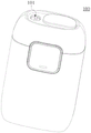
Fig. 1-2 illustrate an aerosol-generating device 100 according to an embodiment of the present disclosure, including:
the casing 10 has an accommodating space therein, and can accommodate the heater 12, the battery cell 13, the circuit 14, and the like. The housing 10 has opposite proximal and distal ends, the proximal end being provided with a through hole 101 and the distal end being provided with an air inlet 102, i.e. the through hole 101 and the air inlet 102 are spaced apart. In other examples, the air inlet 102 may be part of the through hole 101, for example: after the aerosol-forming substrate may be received in the chamber 11 through the through-hole 101, air flows in from the gap between the aerosol-forming substrate and the through-hole 101, i.e. the gap forms the air inlet 102.
A chamber 11, the aerosol-forming substrate being receivable in the chamber 11 or removable from the chamber 11 through the through-holes 101.
An aerosol-forming substrate is a substrate capable of releasing volatile compounds that can form an aerosol. Such volatile compounds may be released by heating the aerosol-forming substrate. The aerosol-forming substrate may be solid or liquid or comprise solid and liquid components. The aerosol-forming substrate may be adsorbed, coated, impregnated or otherwise loaded onto a carrier or support. The aerosol-forming substrate may conveniently be part of an aerosol-generating article.
The aerosol-forming substrate may comprise nicotine. The aerosol-forming substrate may comprise tobacco, for example may comprise a tobacco-containing material containing volatile tobacco flavour compounds which are released from the aerosol-forming substrate when heated. A preferred aerosol-forming substrate may comprise homogenised tobacco material. The aerosol-forming substrate may comprise at least one aerosol-former, which may be any suitable known compound or mixture of compounds that, in use, facilitates the formation of a dense and stable aerosol and is substantially resistant to thermal degradation at the operating temperature of the aerosol-generating system. Suitable aerosol-forming agents are well known in the art and include, but are not limited to: polyhydric alcohols such as triethylene glycol, 1, 3-butanediol and glycerin; esters of polyhydric alcohols, such as glycerol mono-, di-or triacetate; and fatty acid esters of mono-, di-or polycarboxylic acids, such as dimethyldodecanedioate and dimethyltetradecanedioate. Preferred aerosol formers are polyhydric alcohols or mixtures thereof, such as triethylene glycol, 1, 3-butanediol, and most preferably glycerol.
A heater 12 for generating infra-red light to radiatively heat aerosol-forming substrate received in the chamber 11.
The cells 13 provide power for operating the aerosol-generating device 100. For example, the cells 13 may provide power to heat the heater 12. Furthermore, the cells 13 may provide the power required to operate other elements provided in the aerosol-generating device 100.
The cells 13 may be rechargeable batteries or disposable batteries. The battery cell 13 may be, but is not limited to, a lithium iron phosphate (LiFePO4) battery. For example, the cell 13 may be a lithium cobaltate (LiCoO2) battery or a lithium titanate battery.
The circuit 14 may control the overall operation of the aerosol-generating device 100. The circuit 14 controls the operation of not only the cell 13 and the heater 12, but also other elements in the aerosol-generating device 100. For example: the circuit 14 acquires temperature information of the heater 12 sensed by the temperature sensor, and controls the electric power supplied to the heater 12 from the battery cell 13 according to the information.
Fig. 3 is a heater 12 according to an embodiment of the present application, where the heater 12 includes:
the base body 121 is configured in a tubular shape extending in the axial direction of the chamber 11 and surrounding the chamber 11.
In particular, substrate 121 includes a first end and a second end, a surface extending between the first end and the second end. The substrate 121 may be cylindrical, prismatic, or other cylindrical shape. The substrate 121 is preferably cylindrical and a cylindrical bore through the middle of the substrate 121 forms at least part of the chamber, the bore having an inner diameter slightly larger than the outer diameter of the aerosol-forming article to facilitate placing the aerosol-forming article in the chamber for heating thereof.
The substrate 121 may be made of a transparent material such as quartz glass, ceramic or mica, which is resistant to high temperature, or may be made of other materials having high infrared transmittance, for example: the high temperature resistant material having an infrared transmittance of 95% or more is not particularly limited.
An infrared electrothermal coating 122 is formed on the surface of the substrate 121. The infrared electrothermal coating 122 may be formed on the outer surface of the substrate 121, or may be formed on the inner surface of the substrate 121.
The infrared electrothermal coating 122 receives electric power to generate heat, and further generates infrared rays with certain wavelengths, such as: 8-15 μm far infrared ray. When the wavelength of the infrared light matches the absorption wavelength of the aerosol-forming substrate, the energy of the infrared light is readily absorbed by the aerosol-forming substrate. The wavelength of the infrared ray is not limited, and may be an infrared ray of 0.75 to 1000. mu.m, preferably a far infrared ray of 1.5 to 400 μm.
The infrared electrothermal coating 122 is preferably formed by fully and uniformly stirring far infrared electrothermal ink, ceramic powder and an inorganic binder, then coating the mixture on the outer surface of the substrate 121, and then drying and curing the mixture for a certain time, wherein the thickness of the infrared electrothermal coating 122 is 30-50 μm; certainly, the infrared electrothermal coating 122 can also be formed by mixing and stirring tin tetrachloride, tin oxide, antimony trichloride, titanium tetrachloride and anhydrous copper sulfate according to a certain proportion and then coating the mixture on the outer surface of the substrate 121; or one of a silicon carbide ceramic layer, a carbon fiber composite layer, a zirconium-titanium oxide ceramic layer, a zirconium-titanium nitride ceramic layer, a zirconium-titanium boride ceramic layer, a zirconium-titanium carbide ceramic layer, an iron oxide ceramic layer, an iron nitride ceramic layer, an iron boride ceramic layer, an iron carbide ceramic layer, a rare earth oxide ceramic layer, a rare earth nitride ceramic layer, a rare earth boride ceramic layer, a rare earth carbide ceramic layer, a nickel-cobalt oxide ceramic layer, a nickel-cobalt nitride ceramic layer, a nickel-cobalt boride ceramic layer, a nickel-cobalt carbide ceramic layer or a high silicon molecular sieve ceramic layer; the infrared electrothermal coating can also be a coating of other materials, such as: derivatives and compounds of carbon as part or all of the constituent elements, including but not limited to carbon nanotubes, carbon nanotube films, graphene, carbon fibers, carbon fiber films, carbon fiber cloth.
And a conductive element including a first electrode 123 and a second electrode 124 spaced apart on the substrate 121 for feeding the electric power to the infrared electrothermal coating 122.
The first electrode 123 and the second electrode 124 are each at least partially in electrical communication with the infrared electro-thermal coating 122 such that current can flow from one electrode to the other electrode via the infrared electro-thermal coating 122. The first electrode 123 and the second electrode 124 are opposite in polarity, for example: the first electrode 123 is a positive electrode, and the second electrode 124 is a negative electrode; alternatively, the first electrode 123 is a negative electrode and the second electrode 124 is a positive electrode.
In this example, the first electrode 123 and the second electrode 124 are both conductive coatings, the conductive coatings may be metal coatings or conductive tapes, and the like, and the metal coatings may include silver, gold, palladium, platinum, copper, nickel, molybdenum, tungsten, niobium, or metal alloy materials thereof.
In this example, the first electrode 123 and the second electrode 124 are symmetrically disposed along the central axis of the base 121.
The first electrode 123 includes a coupling electrode 1231 extending along a circumferential direction of the substrate 121 and a bar electrode 1232 extending from the coupling electrode 1231 toward the proximal axial direction, the coupling electrode 1231 is not in contact with the infrared electrothermal coating 122, and the bar electrode 1232 is at least partially in contact with the infrared electrothermal coating 122 to form an electrical connection.
The second electrode 124 includes a coupling electrode 1241 extending in a circumferential direction of the base 121 and a bar electrode 1242 extending from the coupling electrode 1241 toward the proximal end a in an axial direction, the coupling electrode 1241 is not in contact with the infrared electrothermal coating 122, and the bar electrode 1242 is at least partially in contact with the infrared electrothermal coating 122 to form an electrical connection.
From the foregoing, the distribution distance between the strip-shaped electrode 1232 and the strip-shaped electrode 1242 is uniform, so that the infrared electrothermal coating 122 can be ensured to be uniformly heated, and the heating efficiency of the smoking set is improved. The arrangement of coupling electrode 1231 and coupling electrode 1241 facilitates coupling with battery core 13, and avoids the problem that a wire connected at one end needs to be damaged easily through a heating area.
Further, referring to fig. 2, the aerosol-generating device 100 further includes an insulating tube 15 sleeved outside the base 121. The heat insulating pipe 15 has an inner pipe and an outer pipe arranged in a radial direction, and a sealed space is formed between the inner pipe and the outer pipe, and a vacuum can be drawn in the sealed space, and gas and heat insulating materials can be filled in the sealed space. The gas includes but is not limited to inert gas, air, carbon dioxide, etc., and the thermal insulation material includes but is not limited to aerogel, mica sheet, mica tube, alumina microporous ceramic, cordierite, rock wool board or rock wool felt, etc.
It should be noted that the infrared emitter composed of the infrared electrothermal coating 122, the first electrode 123 and the second electrode 124 is not limited to the example of fig. 3. In other examples, the infrared emitter may be formed from a thermally-excited infrared radiation layer, or from a thin film construction that may be wound on the substrate 121, or the like.
In the above example, the heater 12 is described as an infrared heating method. In other examples, the heating manner of the heater 12 may also be resistance heating, electromagnetic heating, and the like, but is not limited thereto.
Referring again to fig. 2, the aerosol-generating device 100 further comprises a heat removal device 16.
The heat removal device 16 is disposed on a gas flow path (indicated by a dotted arrow in the figure) extending between the air inlet 102, the chamber 11, and the through hole 101. Specifically, the heat exhausting means 16 is provided between the air inlet 102 and the chamber 11, and the heat exhausting means 16 is configured such that, after the starting operation, the direction of the exhausted airflow is toward the through hole 101, i.e., the direction indicated by the broken-line arrow in the figure. It will be appreciated that it is also possible to direct the exhaust air flow towards the air inlet 102. The exiting air flow is directed towards the through-hole 101 and may advantageously expel the water component of the aerosol-generating article out of the housing. Heat removal device 16 may be a fan or the like.
And a circuit 14 configured to control the heat exhausting means 16 to operate to exhaust the heated air generated by the heating out of the housing 10 along the air flow path after the heater 12 starts heating and before the heater 12 enters the suction stage.
Referring to fig. 4, generally, the temperature profile of the heater 12 over time includes a heating phase, a holding phase and a pumping phase.
During the warm-up phase, the temperature of the heater 12 is increased from the initial temperature T0 (or ambient temperature) to the maximum operating temperature T1. Generally, T1 can be from 150 ℃ to 400 ℃.
During the hold phase, the temperature of the heater 12 is maintained at the preset target temperature T1 for a period of time to allow sufficient preheating of the aerosol-forming substrate to enhance the mouth feel of the puff by the user.
The duration time of the temperature rising stage is t 0-t 2, the duration time of the heat preservation stage is t 2-t 3, and t 0-t 3 are the preheating time of the heater 12. Generally, the preheating time of the heater 12 is 5 seconds to 30 seconds.
During the draw phase, the temperature of the heater 12 drops from the maximum operating temperature T1 to a desired operating temperature T2, the desired operating temperature T2 being the optimum temperature at which the aerosol-forming substrate produces an aerosol. Generally, T2 can be from 150 ℃ to 350 ℃. At this stage, the temperature of the heater 12 is generally maintained at the desired operating temperature T2 or fluctuates above and below the desired operating temperature T2, with T4-T5 being the hold time.
It should be noted that the heating curve of the heater 12 is not limited to the case of fig. 4. In other examples, it is also possible that the heating profile of the heater 12 has only a warm-up phase and a pumping phase.
As can be seen from fig. 4, in order to avoid the problem that the smoker feels the smoke temperature higher during the first puff and causes burning sensation, the circuit 14 should control the heat discharging device 16 to activate to discharge the heated air generated by heating out of the casing 10 along the air flow path before the smoking stage (time point t3 or t 4).
In an example, the aerosol-generating device 100 further comprises a temperature detection device (not shown in the figures) for detecting temperature information of the heater 12;
a circuit 14 configured to acquire temperature information of the heater 12 detected by the temperature detection means after the heater 12 starts heating; when the temperature of the heater 12 reaches a preset temperature, the heat discharging device 16 is controlled to start to work so as to discharge aerosol generated by heating out of the housing 10 along the gas flow path.
Wherein the preset temperature is less than the maximum operating temperature T1 of the heater 12, i.e. before the time point T2, the heat discharging device 16 is controlled to start to discharge the aerosol generated by heating out of the housing 10 along the gas flow path.
In one example, the circuit 14 is configured to time the heating time of the heater 12 after the heater 12 starts heating; when the heating time of the heater 12 reaches a preset time, the heat discharging device 16 is controlled to start to work so as to discharge the aerosol generated by heating out of the shell 10 along the gas flow path.
Wherein the preset time is less than a duration of time for which the temperature of the heater 12 is raised from the initial temperature to the maximum operating temperature. That is, the heat discharging device 16 is controlled to be activated to discharge the aerosol generated by heating out of the housing 10 along the gas flow path before the time point t 2.
Further, at time T10, the heating temperature T10 of the heater 12 is such that most of the moisture in the tobacco rod is evaporated, and therefore at time T10, the heat exhausting device 16 is controlled to operate to exhaust the heated air out of the housing 10 along the air flow path, so as to avoid the problem that the aerosol generated by heating is exhausted out of the housing 10 along the air flow path near the smoking stage, which leads to the smoker feeling a small amount of smoke and reduces the smoking experience when smoking the first mouth. Generally, T10 can be between 80 ℃ and 200 ℃.
Further, the circuit 14 is also configured to control the heat removal device 16 to cease operation when a smoker can puff on the aerosol-generating device 100. That is, during the time of user smoking (period t 4-t 5), the heat removal device 16 stops working, and the user can smoke with relatively low temperature.
It should be noted that the heat removal device 16 is not limited to this case. For example: the heat removal device 16 is deactivated after a period of operation and does not wait until the aerosol-generating device 100 is available for a smoker to smoke. It is easily conceivable that the operating power of the heat removal device 16 is also adjustable during operation of the heat removal device 16, i.e. the heat removal device 16 is controlled to operate for a certain time with a certain operating power.
The present application further provides, based on the aerosol-generating device 100, a method of controlling an aerosol-generating device, the method comprising:
controlling the heat exhausting means 16 to operate to exhaust the heated air generated by the heating out of the casing 10 along the air flow path after the heater 12 starts heating and before the heater 12 enters the suction stage;
wherein the temperature profile of the heater 12 comprises at least a heating phase and a pumping phase.
Figure 5 is a schematic diagram of a control process for an aerosol-generating device provided by an embodiment of the present application. The control process for an aerosol-generating device comprises the steps of:
s31, after the cigarette is inserted into the chamber 11, the heater 12 can be controlled to start heating;
s32, acquiring the temperature information of the heater 12 detected by the temperature sensor;
s33, determine whether the heater 12 is greater than or equal to the preset temperature?
S34, if the temperature of the heater 12 is greater than or equal to the preset temperature, controlling the heat discharging device 16 to start working; otherwise, continuing to execute step S32 (step S35);
s36, the heat discharging device 16 discharges the aerosol generated by heating out of the housing 10 along the gas flow path;
s37, determine whether the heater 12 enters the pumping stage?
S38, if the heater 12 enters the suction stage, controlling the heat discharging device 16 to stop working; otherwise, continuing to execute step S37 (step S39);
s40, the user starts pumping.
It should be noted that the description of the present application and the accompanying drawings set forth preferred embodiments of the present application, however, the present application may be embodied in many different forms and is not limited to the embodiments described in the present application, which are not intended as additional limitations to the present application, but are provided for the purpose of providing a more thorough understanding of the present disclosure. Moreover, the above-mentioned technical features are combined with each other to form various embodiments which are not listed above, and all the embodiments are regarded as the scope described in the present specification; further, modifications and variations may occur to those skilled in the art in light of the foregoing description, and it is intended to cover all such modifications and variations as fall within the scope of the appended claims.