Infrared heating device with light shield plate
[ technical field ] A method for producing a semiconductor device
The invention relates to the technical field of infrared heating, in particular to an infrared heating device with a photomask plate.
[ background of the invention ]
Infrared heating (IR heating for short) means that when infrared rays are irradiated to an object to be heated, the infrared rays are absorbed by the object to be heated when the wavelength of the emitted infrared rays is identical to the absorption wavelength of the object to be heated, and molecules in the object resonate to increase the temperature of the object, thereby achieving the purpose of heating. The infrared heating method has the advantages of no need of heat transfer medium transmission, good heat efficiency, etc., and is widely applied to various fields, such as thermoplastic material molding.
The infrared heater heats a target object in a non-contact mode, however, when the heated object has local high and low temperature requirements, the existing infrared heating equipment can only divide an infrared irradiation area by means of copper foil pasting, heat-resistant glue and the like, so that additional auxiliary materials are required to be added, and the cost cannot be saved.
Therefore, it is necessary to develop an infrared heating apparatus having a photo-mask plate to solve the above problems.
[ summary of the invention ]
The invention aims to provide an infrared heating device with a light cover plate, wherein the light cover plate is adopted to divide an infrared irradiation area, no auxiliary material is required to be additionally added, and the cost is saved.
In order to achieve the purpose, the invention provides the following technical scheme:
an infrared heating device having a light shield plate, comprising:
a box body which is provided with an opening and is used for placing a product to be heated;
the infrared heating module is arranged in the box body, and infrared rays emitted by the infrared heating module heat the product;
the optical cover plate is arranged between the infrared heating module and a product, a hole set comprising a plurality of through holes is arranged on the optical cover plate, the density and the size of the through holes corresponding to different hole sets are different, and infrared rays emitted by the infrared heating module heat the product through the through holes.
Further, the infrared heating module comprises at least one infrared heating lamp tube, and the wavelength of infrared rays emitted by the infrared heating lamp tube is the same as the absorption wavelength of the product, so that the product is heated in an infrared mode.
Furthermore, the infrared heating lamp tube is arranged in a continuous U shape; or the infrared heating lamp tubes are arranged side by side.
Furthermore, the infrared heating lamp tube is a ceramic lamp tube.
Further, the through hole is a circular hole, a rectangular hole, a tapered hole or a stepped hole having a stepped surface.
Further, at least two different sets of apertures have overlapping infrared illumination areas.
Further, the area excluding the aperture set on the photomask plate is a shielding area, and the shielding area reflects infrared rays emitted by the infrared heating module back to the infrared heating module.
Further, the product is arranged in the middle of the box body, the infrared heating modules are respectively arranged on the upper side and the lower side of the box body to heat the two surfaces of the product, correspondingly, the number of the light cover plates is two, and the two light cover plates are respectively arranged between the infrared heating modules and the product.
Furthermore, a positioning jig with a hollow middle part is further arranged in the box body, and the product is placed on the positioning jig.
Compared with the prior art, the infrared heating device with the light cover plate does not need additional auxiliary materials such as aluminum foil and heat-resistant adhesive tapes, the light cover plate is arranged in the infrared heating device, the light cover plate is provided with the hole sets comprising the through holes, the density and the size of the through holes corresponding to different hole sets are different, infrared rays emitted by the infrared heating module heat products through the through holes, so that the intensity of the infrared rays passing through different hole sets is different, the temperature of the corresponding heated products is different, the high-temperature region and the low-temperature region of infrared heating are divided, and the effects of high efficiency, accurate heating and energy conservation are achieved.
[ description of the drawings ]
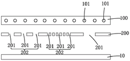
FIG. 1 is a schematic view of an infrared heating apparatus having a cover plate according to the present invention.
FIG. 2 is a schematic view of an infrared heating module of the present invention.
FIG. 3 is a schematic view of a mask plate according to the present invention.
Fig. 4 is a schematic view of the infrared heating device with a cover plate for infrared heating according to the present invention.
FIG. 5 is a schematic view of an infrared heating apparatus having a shadow mask according to a preferred embodiment of the present invention.
FIG. 6 is a schematic diagram of the infrared heating of FIG. 5.
[ detailed description ] embodiments
For a further understanding of the objects, technical effects and technical means of the present invention, reference will now be made in detail to the following description taken in conjunction with the accompanying drawings.
Referring to fig. 1 to 3, fig. 1 is a schematic view of an infrared heating apparatus having a light shield plate according to the present invention, fig. 2 is a schematic view of an infrared heating module according to the present invention, and fig. 3 is a schematic view of a light shield plate according to the present invention.
The present invention provides an infrared heating apparatus having a shadow mask for rapidly infrared heating a product 10, the product 10 may be a thermoplastic carbon fiber board, the apparatus includes:
a box (not shown) having an opening, into which the product 10 to be heated is put, the opening can be arranged at the side or bottom of the box according to actual conditions, for example, when the product 10 is arranged in the middle of the box, the opening is arranged at the side of the box, when the product 10 is arranged at the bottom of the box, the opening is arranged at the bottom of the box;
the infrared heating module 100 is arranged in the box body, infrared rays emitted by the infrared heating module 100 heat the product 10, and specifically, when the wavelength of the infrared rays emitted by the infrared heating module 100 is the same as the absorption wavelength of the product 10, resonance is generated, so that the purpose of rapid heating is achieved;
the photomask plate 200 is arranged between the infrared heating module 100 and the product 10, a hole set 202 comprising a plurality of through holes 201 is arranged on the photomask plate 300, the density and/or the size of the through holes 201 corresponding to different hole sets 202 are different, and the infrared rays emitted by the infrared heating module 100 heat the product 10 through the through holes 201. The density and size of the through holes 201 affect the infrared heating strength, for example, when the sizes of the through holes 201 are the same, the hole set 202 with the high density of the through holes 201 can achieve the effect of local temperature rise; or, when the density of the through holes 201 is the same, the hole set 202 with the large size of the through holes 201 can achieve the effect of local temperature rise. Therefore, the infrared irradiation position and the illumination can be planned according to the requirement of the product 10, and the specific position, density and size of the through holes 201 of the photomask plate 200 can be further designed.
The infrared heating module 100 includes at least one infrared heating lamp 101, the infrared wavelength released by the infrared heating lamp 101 is the same as the absorption wavelength of the product 10, so as to heat the product 10, and in order to adapt to different products 10, different types of infrared heating lamps 101 can be replaced according to products 10 made of different materials, and the heating power of the infrared heating lamps 101 is adjustable. Further, when one infrared heating lamp tube 101 is provided, the infrared heating lamp tube 101 is continuously arranged in a U shape; or when the infrared heating lamp tube 101 has multiple heels, the multiple infrared heating lamp tubes 101 are arranged side by side. Furthermore, the infrared heating lamp 101 is a ceramic lamp.
For convenience of processing the through hole 201, the through hole 201 may be a circular hole, a rectangular hole, a tapered hole or a stepped hole having a stepped surface, although not limited thereto, in a preferred embodiment, the through hole 201 is a circular hole, and the size of the through hole 201 is represented by the diameter of the circular hole.
At least two different hole sets 202 have overlapped infrared irradiation areas 203, the overlapped infrared irradiation areas 203 irradiate on the product 10, the infrared heating effect of the corresponding area of the product 10 is enhanced, and the product 10 achieves the effect of local heating.
Referring to fig. 1 and 3, the area excluding the hole set 202 on the light cover plate 200 is a shielding area, and the shielding area reflects the infrared rays emitted by the infrared heating module 100 back to the infrared heating module 100, so as to save energy consumption.
FIG. 5 is a schematic view of an infrared heating apparatus having a shadow mask according to a preferred embodiment of the present invention. In a preferred embodiment, in order to heat the two sides of the product 10 uniformly, the product 10 is not deformed during the heating process, the product 10 is disposed in the middle of the box, a positioning fixture with a hollow center is disposed in the box, the product 10 is placed on the positioning fixture, the positioning fixtures with different sizes can be replaced according to the size of the product 10, the infrared heating modules 100 are respectively disposed on the upper and lower sides of the box to heat the two sides of the product 10, and correspondingly, the number of the light cover plates 200 is two, and the two light cover plates are respectively disposed between the infrared heating modules 100 and the product 10.
Referring to fig. 4 and 6, when the product 10 is heated, the infrared heating module 100 emits infrared rays, and the infrared rays pass through the through holes 201 of the photomask plate 200 and then perform infrared heating on the product 10, as shown in fig. 4 and 6, the dotted lines indicate the areas through which the infrared rays pass, and the density and size of the through holes 201 enable different areas of the product 10 to have different infrared heating effects.
In summary, in the infrared heating device with the photo-mask plate of the present invention, additional auxiliary materials such as aluminum foil, heat-resistant adhesive tape, etc. are not needed, but the photo-mask plate 200 is disposed in the infrared heating device, the photo-mask plate 200 is provided with the hole sets 202 including the plurality of through holes 201, the density and the size of the through holes 201 corresponding to different hole sets 202 are different, and the infrared rays emitted by the infrared heating module 100 heat the product 10 through the through holes 201, so that the intensity of the infrared rays passing through different hole sets 202 is different, the temperature of the corresponding heated product 10 is different, and thus the infrared heating high-temperature region, the infrared heating low-temperature region, etc. are divided, and the effects of high efficiency, precise heating, and energy saving are achieved.
The technical principles of the present invention have been described above in connection with specific embodiments, which are intended to explain the principles of the present invention and should not be construed as limiting the scope of the present invention in any way. Based on the explanations herein, those skilled in the art will be able to conceive of other embodiments of the present invention without inventive effort, which would fall within the scope of the present invention.