Disclosure of Invention
The oscillator circuit needs a large current and power consumption when starting oscillation, and often only needs a small current to maintain the oscillation state after starting oscillation, and the minimum working current required for maintaining oscillation is difficult to obtain, so in order to ensure that the oscillator can maintain the oscillation state after starting oscillation, the working current of the oscillator must be designed to ensure the normal operation of the oscillator, which inevitably increases the current and power consumption of the oscillator.
In view of the foregoing problems, embodiments of the present invention provide a method, a circuit and a device for reducing power consumption of an oscillator in an integrated circuit, which can at least partially solve the problems in the prior art.
In a first aspect, the present invention provides a method for reducing power consumption of an oscillator in an integrated circuit, including:
determining the working state of the oscillator according to the oscillator output signal acquired by the filter;
executing an iteration step, wherein the iteration step comprises reducing working current and regenerating an output signal according to the working current if the output signal of the oscillator is in a preset interval and the oscillator is in a normal working state, and replacing an initial output signal with the regenerated output signal until the output signal is not in the preset interval and the oscillator is in a starting state, so as to obtain a final output signal;
and after the oscillator starts oscillation, switching to the final output signal so as to enable the oscillator to work with the minimum working current, thereby reducing the power consumption of the oscillator.
Further, the determining the corresponding current control signal in the low power consumption state of the oscillator includes:
initializing the oscillator.
Further, the initializing the oscillator includes:
adjusting the oscillator to a non-oscillation state;
adjusting the variable current of the oscillator to a maximum value.
In a second aspect, the present invention provides a circuit for reducing power consumption of an oscillator in an integrated circuit, including:
a low-pass filtering module: the current signal is used for extracting and judging a periodic signal output by the oscillator to be tested;
a current control module: the low-pass filtering module is used for controlling the current and the power consumption of the oscillating module according to the judgment result of the low-pass filtering module and generating a mark signal so as to enable the server to execute an iteration step, wherein the iteration step comprises the steps of reducing the working current and regenerating an output signal according to the working current if the output signal of the oscillator is in a preset interval and the oscillator is in a normal working state, and replacing the initial output signal with the regenerated output signal until the output signal is not in the preset interval and the oscillator is in a vibration starting state so as to obtain a final output signal; and after the oscillator starts oscillation, switching to the final output signal so as to enable the oscillator to work with the minimum working current, thereby reducing the power consumption of the oscillator.
Further, the circuit further comprises:
a buffer counting module: the output signal of the oscillator to be tested can be shaped, converted into a periodic signal with large swing amplitude, and the periodic signal is counted.
Further, the circuit further comprises:
a window comparison module: and the current control module is used for judging whether the current signal extracted by the low-pass filtering module is in a set range or not and outputting a judgment result to the current control module.
Further, the buffer count module includes:
a buffer assembly: the output signal of the oscillation unit can be converted into a periodic signal with large swing amplitude;
a counting component: the current control module is used for counting the period number of the periodic signal output by the buffer component and outputting the counting result to the current control module so as to enable the current control module to judge the working state of the oscillation module according to the counting result.
Further, the circuit further comprises:
variable current bias module: and the current control module is used for generating an output signal according to the current control module to generate a variable bias current for the oscillator to be tested to work.
In a third aspect, the invention provides an apparatus for reducing power consumption of an oscillator in an integrated circuit comprising the above circuit.
The invention has the advantages of
In the method, the circuit and the apparatus for reducing power consumption of the oscillator in the integrated circuit according to the embodiments of the present invention, when the oscillator oscillates, the voltage signal of the oscillator whose output signal passes through the buffer (shaping) circuit is usually a large swing or full swing signal, the dc component of the oscillator is usually at or near the middle potential of the power supply, and when the oscillator does not start oscillation, the voltage signal of the oscillator whose output signal passes through the buffer (shaping) circuit is usually at a higher (highest) potential or a lower (lowest) potential. The invention provides a method for detecting whether an oscillator oscillates or not and a realization circuit by utilizing the characteristic of an output signal of the oscillator, and provides a method for obtaining the minimum current required by the oscillator for maintaining an oscillation state on the basis of the method, so that the minimum current for the oscillator to work can be accurately found, and after the minimum current for the oscillator to work is found, the oscillator keeps the minimum current to work after oscillation starting, and the whole working current and the power consumption of the oscillator circuit can be reduced by more than half.
Detailed Description
In order to make the objects, technical solutions and advantages of the embodiments of the present invention more apparent, the embodiments of the present invention are further described in detail below with reference to the accompanying drawings. The exemplary embodiments and descriptions of the present invention are provided to explain the present invention, but not to limit the present invention. It should be noted that the embodiments and features of the embodiments in the present application may be arbitrarily combined with each other without conflict.
At present, an oscillator circuit needs a large current and power consumption when starting oscillation, and often only needs a small current to maintain an oscillation state after starting oscillation, and a minimum working current required for maintaining oscillation is difficult to obtain.
Based on this, as shown in fig. 1, the present invention provides a method for reducing power consumption of an oscillator in an integrated circuit, comprising:
step S100: determining the working state of the oscillator according to the oscillator output signal acquired by the filter;
step S200: executing an iteration step, wherein the iteration step comprises reducing working current and regenerating an output signal according to the working current if the output signal of the oscillator is in a preset interval and the oscillator is in a normal working state, and replacing an initial output signal with the regenerated output signal until the output signal is not in the preset interval and the oscillator is in a starting state, so as to obtain a final output signal;
step S300: and after the oscillator starts oscillation, switching to the final output signal so as to enable the oscillator to work with the minimum working current, thereby reducing the power consumption of the oscillator.
It can be understood that the filter can effectively filter the frequency point of the specific frequency in the power line or frequencies other than the frequency point to obtain a power signal of the specific frequency, or eliminate the power signal of the specific frequency. Because the voltage signal of the oscillator output signal after passing through the buffer (shaping) circuit is usually a large-swing or full-swing signal when oscillating, and the direct current component thereof is usually at or near the middle potential of the power supply, and the voltage signal of the oscillator output signal after passing through the buffer (shaping) circuit when not oscillating is usually at a higher (highest) potential or a lower (lowest) potential, the working state of the oscillator can be determined according to the oscillator output signal collected by the filter, and the oscillator output signal can be a current signal or a voltage signal. Judging an output signal of the oscillator, if the output signal is in a preset interval and the oscillator can maintain a normal working state under the current working current condition, recording the current output signal at the moment, reducing the working current, regenerating a corresponding output signal, taking the regenerated output signal as an input signal of the oscillator until the output signal of the oscillator is not in the set interval and the oscillator is in a starting state, and finally taking the output signal as the output signal when the oscillator works at the minimum current; after the oscillator starts oscillation, the oscillator is switched to a final output signal so that the oscillator works with the minimum working current, and the power consumption of the oscillator is further reduced.
As can be seen from the above description, in the method for reducing power consumption of the oscillator in the integrated circuit provided in the embodiments of the present application, the voltage signal of the output signal of the oscillator after passing through the buffer (shaping) circuit when the oscillator oscillates is usually a large swing or full swing signal, the dc component of the voltage signal is usually at or near the middle potential of the power supply, and the voltage signal of the output signal of the oscillator after passing through the buffer (shaping) circuit when the oscillator is not oscillating is usually at a higher (highest) potential or a lower (lowest) potential. The invention provides a method for detecting whether an oscillator oscillates or not by utilizing the characteristic of an output signal of the oscillator, and provides a method for obtaining the minimum current required by the oscillator for maintaining an oscillation state on the basis of the characteristic, the working signal of the oscillator is continuously detected, the minimum current for the oscillator to work can be accurately found, and after the minimum current for the oscillator to work is found, the oscillator keeps the minimum current to work after oscillation starting, so that the whole working current and power consumption of an oscillator circuit can be reduced by more than half.
In some embodiments, as shown in fig. 1, the determining the corresponding current control signal in the low power consumption state of the oscillator includes:
step S001: initializing the oscillator.
It will be appreciated that the oscillator circuit is powered up for initialization, the main operations including setting the oscillator to a state where it has not yet fully started, while setting the input variable current of the oscillator to the maximum current IMAX;
another aspect of the present invention provides a circuit for reducing power consumption of an oscillator in an integrated circuit, as shown in fig. 2, including:
a low-pass filtering module: the current signal is used for extracting and judging a periodic signal output by the oscillator to be tested;
a current control module: the low-pass filtering module is used for controlling the current and the power consumption of the oscillating module according to the judgment result of the low-pass filtering module and generating a mark signal so as to enable the server to execute an iteration step, wherein the iteration step comprises the steps of reducing the working current and regenerating an output signal according to the working current if the output signal of the oscillator is in a preset interval and the oscillator is in a normal working state, and replacing the initial output signal with the regenerated output signal until the output signal is not in the preset interval and the oscillator is in a vibration starting state so as to obtain a final output signal; and after the oscillator starts oscillation, switching to the final output signal so as to enable the oscillator to work with the minimum working current, thereby reducing the power consumption of the oscillator.
It can be understood that the application circuit structure of the low-pass filtering module includes, but is not limited to, a passive RC filter, an active RC filter, etc., and is mainly used for extracting a direct-current component (which may be a voltage signal or a current signal) of the periodic signal output by the buffer circuit, and generally, the upper limit frequency of the low-pass filtering module should be smaller than the output signal frequency of the oscillator. The current control module is used for controlling the current and the power consumption of the oscillator in the oscillation starting and stabilizing stages. A current control module: the signal M has two states, wherein the state of the signal M is 0 to indicate that the oscillator is not completely started from power-on, and the state of the signal M is 1 to indicate that the oscillator is completely started from power-on and is kept for a period of time. Judging the oscillator output signal acquired by the low-pass filtering module, recording the current output signal if the output signal is in a preset interval and the flag signal M of the current control module is in a state 1, reducing the working current, regenerating the corresponding output signal, and taking the regenerated output signal as the input signal of the oscillator until the output signal of the oscillator is not in the preset interval and the flag signal M of the current control module is in a state 1, wherein the final output signal is the output signal of the oscillator working at the minimum current; after the oscillator starts oscillation, the oscillator is switched to a final output signal so that the oscillator works with the minimum working current, and the power consumption of the oscillator is further reduced.
In some specific embodiments, as shown in fig. 2, the circuit further comprises:
a buffer counting module: the output signal of the oscillator to be tested can be shaped, converted into a periodic signal with large swing amplitude, and the periodic signal is counted.
It can be understood that the buffering and counting module includes a buffering component and a counting component, the buffering component is used for improving the driving capability of the oscillator to be tested and has a certain shaping function, and the output of the buffering component is a large-swing-amplitude periodic signal; the counting component is a counter and can be used for counting the period number of the periodic signal output by the buffer component and counting the counting result NCAnd the output is output to a current control module which is mainly used for judging whether the oscillator is in a stable oscillation working state.
In some specific embodiments, as shown in fig. 2, the circuit further comprises:
a window comparison module: and the current control module is used for judging whether the current signal extracted by the low-pass filtering module is in a set range or not and outputting a judgment result to the current control module.
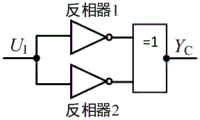
It is understood that the window comparison module is a window comparator, and the applied circuit structure thereof includes and is not limited to the window comparator formed by using the analog operational amplifier as shown in fig. 3, the window comparator formed by using the inverters with different threshold voltages as shown in fig. 4, and the like. The inverter 1 and the inverter 2 in fig. 4 have different threshold voltages U, respectivelyRHAnd URLThe output signals of the two inverters passing through the XOR gate (or the XNOR gate) can be used as the output signal of the low pass filter to determine whether the output signal falls within a predetermined interval (U)RHAnd URLAnd, in) is determined. Further, the window comparator may also employ a comparator circuit having a hysteresis characteristic. The window comparison module is used for receiving the direct current component extracted by the low-pass filtering module, judging whether the direct current component output by the low-pass filtering module falls in a certain specific range or not, and outputting a judgment result YC to the current control circuit; the current control circuit generates a reset signal R of the counter according to the output result of the window comparator and the counting result of the counterCAnd a current control signal CIAnd the method is used for controlling the current and the power consumption of the oscillator in the oscillation starting and stabilizing stages.
In some specific embodiments, as shown in fig. 2, the circuit further comprises:
variable current bias module: and the current control module is used for generating an output signal according to the current control module to generate a variable bias current for the oscillator to be tested to work.
It can be understood that the variable current bias module and the oscillator circuit may be configured as shown in fig. 5 and fig. 6, and are mainly used for providing a variable current bias to the oscillator according to the output signal generated by the current control module, which directly controls the current and power consumption of the oscillator under test. The applied circuit structure includes but is not limited to single-tube analog current source and multi-tube digital control current source. The multi-tube numerical control current source can adopt the figure 7The circuit structure is shown, wherein each current tube can be configured according to binary current magnitude, and the grid of each current tube can be respectively in a maximum current working state (grid connected to VDD), a minimum current working state (grid connected to GND) and a limited current working state (grid connected to V) through a control signalbias)。
As can be seen from the foregoing description, in the circuit for reducing power consumption of the oscillator in the integrated circuit provided in the embodiments of the present application, in order to ensure that the circuit can start oscillation normally and maintain an oscillation state, an operating current of the conventional oscillator circuit is usually set to be more than 2 times of a normal operating current. The invention can accurately find the minimum current of the oscillator by adding the low-pass filter circuit, the window comparator, the counter and the current control circuit, and after the minimum current of the oscillator is found, the low-pass filter circuit, the window comparator and the counter can stop working to reduce power consumption, and the current control circuit can be realized by a digital circuit, so that the static power consumption is very low, thereby reducing the whole working current and the power consumption of the oscillator circuit by more than half.
The present application provides an embodiment of an apparatus for reducing power consumption of an oscillator in an integrated circuit, which is used for implementing all or part of the method for reducing power consumption of an oscillator in the integrated circuit, and the apparatus for reducing power consumption of an oscillator in an integrated circuit specifically includes a circuit for reducing power consumption of an oscillator in an integrated circuit as described in the above.
The method, circuit and apparatus for reducing power consumption of an oscillator in an integrated circuit provided in this embodiment are specifically described below with reference to specific embodiments.
After the oscillator circuit is electrified and starts to work, the following three stages are divided:
the first stage, finding the output signal corresponding to the lowest power consumption, i.e. the current control signal CI0;
In the second stage, the oscillator is set to be at the maximum current so as to start oscillation rapidly;
in the third stage, switching to the current control signal C corresponding to the lowest power consumptionI0The low pass filter module, window comparator and counter are turned off and the oscillator beginsAnd (4) working normally.
Wherein the current control signal C corresponding to the lowest power consumption is searched in the first stageI0The specific operation flow of (2) is shown in fig. 8, which is described as follows:
firstly, the oscillator is powered on for initialization, and the main operations include setting the flag signal M to 0, resetting the counter (clear 0), and setting the variable current to the maximum current IMAX;
Then, continuously detecting whether the output signal of the low-pass filtering module falls within a preset interval (for example, greater than the lower threshold potential UL, and less than the upper threshold potential UL), and according to the detection result, dividing into two cases:
in the first case, if it is detected that the output signal of the low-pass filter falls within the preset interval, whether the counter counts to a preset value is further detected, and the detection result is divided into two cases: (1) if the preset value is detected to be counted, the oscillator can maintain the normal working state under the current working current condition, and the current control signal C can be recorded at the momentIIs CI0Reducing the working current, setting the mark signal M to be in a state 1, and continuously detecting whether the output signal of the low-pass filter falls in a preset interval; (2) if the preset value is not counted, the current oscillation is not completely stable, the current state is kept, and whether the output signal of the low-pass filter falls in the preset interval or not is continuously detected.
In the second case, if it is detected that the output signal of the low-pass filter does not fall within the preset interval, the state of the flag signal M is further detected, and the detection result is divided into two cases: (1) if the marking signal M is in the state 0, the oscillator is not completely started to oscillate from the power-on, the current state is kept, and whether the output signal of the low-pass filter falls in a preset interval or not is continuously detected; (2) if the flag signal M is in state 1, the current control signal C indicates that the oscillator has started to oscillate stably since power-on but has stopped oscillating due to a current decrease, which indicates a minimum operating current of the oscillatorI0Having been found, the flow ends.
In the method, circuit and apparatus for reducing power consumption of an oscillator in an integrated circuit according to embodiments of the present invention, a voltage signal of an output signal of the oscillator after passing through a buffer (shaping) circuit is usually a large swing or full swing signal when the oscillator oscillates, a dc component of the oscillator is usually at or near a middle potential of a power supply, and a voltage signal of the output signal of the oscillator after passing through the buffer (shaping) circuit when the oscillator is not oscillating is usually at a higher (highest) potential or a lower (lowest) potential. The invention provides a method for detecting whether an oscillator oscillates or not and a realization circuit by utilizing the characteristic of an output signal of the oscillator, and provides a method for obtaining the minimum current required by the oscillator for maintaining an oscillation state on the basis of the method, the minimum current for the oscillator to work can be accurately found, after the minimum current for the oscillator to work is found, a low-pass filter circuit, a window comparator and a counter can stop working to reduce power consumption, a current control circuit can be realized by a digital circuit, the static power consumption is very low, and the whole working current and the power consumption of the oscillator circuit can be reduced by more than half.
In the description herein, reference to the description of the terms "one embodiment," "a particular embodiment," "some embodiments," "for example," "an example," "a particular example," or "some examples," etc., means that a particular feature, structure, material, or characteristic described in connection with the embodiment or example is included in at least one embodiment or example of the invention. In this specification, the schematic representations of the terms used above do not necessarily refer to the same embodiment or example. Furthermore, the particular features, structures, materials, or characteristics described may be combined in any suitable manner in any one or more embodiments or examples.
The above-mentioned embodiments are intended to illustrate the objects, technical solutions and advantages of the present invention in further detail, and it should be understood that the above-mentioned embodiments are only exemplary embodiments of the present invention, and are not intended to limit the scope of the present invention, and any modifications, equivalent substitutions, improvements and the like made within the spirit and principle of the present invention should be included in the scope of the present invention.