CN114323250A - Underwater sound detection device, system, target tracking method and device - Google Patents
Underwater sound detection device, system, target tracking method and device Download PDFInfo
- Publication number
- CN114323250A CN114323250A CN202210217666.7A CN202210217666A CN114323250A CN 114323250 A CN114323250 A CN 114323250A CN 202210217666 A CN202210217666 A CN 202210217666A CN 114323250 A CN114323250 A CN 114323250A
- Authority
- CN
- China
- Prior art keywords
- laser
- light intensity
- underwater acoustic
- underwater
- signal
- Prior art date
- Legal status (The legal status is an assumption and is not a legal conclusion. Google has not performed a legal analysis and makes no representation as to the accuracy of the status listed.)
- Granted
Links
- 238000001514 detection method Methods 0.000 title claims abstract description 104
- 238000000034 method Methods 0.000 title claims abstract description 33
- 230000008859 change Effects 0.000 claims abstract description 83
- 238000012545 processing Methods 0.000 claims description 21
- 230000007246 mechanism Effects 0.000 claims description 9
- 230000005236 sound signal Effects 0.000 claims description 9
- 238000001914 filtration Methods 0.000 claims description 7
- 238000010606 normalization Methods 0.000 claims description 4
- 230000000694 effects Effects 0.000 abstract description 10
- 238000010586 diagram Methods 0.000 description 13
- 230000003287 optical effect Effects 0.000 description 11
- 238000004590 computer program Methods 0.000 description 7
- XLYOFNOQVPJJNP-UHFFFAOYSA-N water Substances O XLYOFNOQVPJJNP-UHFFFAOYSA-N 0.000 description 7
- 230000006870 function Effects 0.000 description 6
- 230000001681 protective effect Effects 0.000 description 6
- 230000008569 process Effects 0.000 description 4
- 238000005314 correlation function Methods 0.000 description 3
- 230000010363 phase shift Effects 0.000 description 3
- 230000001902 propagating effect Effects 0.000 description 3
- 230000009471 action Effects 0.000 description 2
- 230000006872 improvement Effects 0.000 description 2
- 239000000463 material Substances 0.000 description 2
- 238000005259 measurement Methods 0.000 description 2
- 230000004048 modification Effects 0.000 description 2
- 238000012986 modification Methods 0.000 description 2
- 230000004044 response Effects 0.000 description 2
- 238000001228 spectrum Methods 0.000 description 2
- 230000003068 static effect Effects 0.000 description 2
- 230000001360 synchronised effect Effects 0.000 description 2
- 230000008901 benefit Effects 0.000 description 1
- 238000004891 communication Methods 0.000 description 1
- 230000007123 defense Effects 0.000 description 1
- 239000012530 fluid Substances 0.000 description 1
- 238000003384 imaging method Methods 0.000 description 1
- 230000003993 interaction Effects 0.000 description 1
- 239000007788 liquid Substances 0.000 description 1
- 239000004973 liquid crystal related substance Substances 0.000 description 1
- 238000005457 optimization Methods 0.000 description 1
- 230000008447 perception Effects 0.000 description 1
- 230000000737 periodic effect Effects 0.000 description 1
- 230000005855 radiation Effects 0.000 description 1
- 239000007787 solid Substances 0.000 description 1
- 230000003595 spectral effect Effects 0.000 description 1
Images


Landscapes
- Measurement Of Mechanical Vibrations Or Ultrasonic Waves (AREA)
Abstract
本发明适用于声光探测技术领域,提供了一种水声探测装置、系统、目标追踪方法和装置,水声探测装置包括基座和设置在基座上的激光发射模块和激光接收模块;激光发射模块用于发射若干束平行激光;激光接收模块用于接收激光发射模块发射出的激光,并获取激光的光强信号;激光发射模块和激光接收模块之间的若干束平行激光构成水声探测区域,当声波引起水声探测区域的介质的折射率发生变化时,激光接收模块接收的光强信号发生变化,进而根据光强信号的变化确定水声信号的相位变化。本申请通过设置激光发射模块和激光接收模块,根据声光效应进行水声探测,有效避免传统声学换能器由机械振动导致的起讫点模糊问题,提高探测精度。

The invention is applicable to the technical field of acousto-optic detection, and provides an underwater acoustic detection device, a system, a target tracking method and device. The underwater acoustic detection device comprises a base, a laser transmitting module and a laser receiving module arranged on the base; a laser The transmitting module is used to transmit several parallel laser beams; the laser receiving module is used to receive the laser light emitted by the laser transmitting module and obtain the light intensity signal of the laser; several parallel laser beams between the laser transmitting module and the laser receiving module constitute underwater acoustic detection When the sound wave causes the refractive index of the medium in the underwater acoustic detection area to change, the light intensity signal received by the laser receiving module changes, and then the phase change of the underwater acoustic signal is determined according to the change of the light intensity signal. In the present application, by setting a laser transmitting module and a laser receiving module, underwater acoustic detection is performed according to the acousto-optic effect, which effectively avoids the blurring of the origin and destination caused by mechanical vibration of the traditional acoustic transducer, and improves the detection accuracy.
Description
技术领域technical field
本发明属于声光探测技术领域,尤其涉及一种水声探测装置、系统、目标追踪方法和装置。The invention belongs to the technical field of acousto-optic detection, and in particular relates to an underwater acoustic detection device, a system, a target tracking method and device.
背景技术Background technique
水声一般指在水下传播的声波,例如,最常用的水下传播的声波为水声,声波是一种波长极短的机械波,水下环境中,声波具有指向性好、易于聚焦、水中传播距离远等特性,广泛应用于水下探测、水声通信、水下成像等领域。水下小型游弋式目标的高分辨定位跟踪对提升海防能力具有重要意义,这些小型目标包括蛙人、小型潜器等,他们的特点是目标小、游弋动作细节多。从主流的定位跟踪原理来看,这些细节性运动特征主要反映在目标信号的相位上,高分辨感知目标声波信号的相位信息,对突破这一类问题有重要意义。Underwater sound generally refers to the sound wave propagating underwater. For example, the most commonly used underwater sound wave is underwater sound. Sound wave is a kind of mechanical wave with extremely short wavelength. It is widely used in underwater detection, underwater acoustic communication, underwater imaging and other fields. High-resolution positioning and tracking of small underwater cruising targets is of great significance for improving coastal defense capabilities. These small targets include frogmen, small submersibles, etc. They are characterized by small targets and many details of cruising movements. From the perspective of mainstream positioning and tracking principles, these detailed motion features are mainly reflected in the phase of the target signal. High-resolution perception of the phase information of the target acoustic signal is of great significance for breaking through this type of problem.
目前,对于水声信号的测量主要是基于压电效应的声学换能器,但是,基于压电效应的换能器的声波相位分辨率存在相对较高的相位分辨阈值,在水下目标探测应用中,探测精度低。At present, the measurement of underwater acoustic signals is mainly based on acoustic transducers based on piezoelectric effect. However, the acoustic wave phase resolution of transducers based on piezoelectric effect has a relatively high phase resolution threshold, which is used in underwater target detection applications. , the detection accuracy is low.
发明内容SUMMARY OF THE INVENTION
本发明实施例的目的在于提供一种水声探测装置,旨在解决现有基于压电效应的水声换能器的声波相位分辨率存在相对较高的相位分辨阈值,在水下目标探测应用中探测精度低的技术问题。The purpose of the embodiments of the present invention is to provide an underwater acoustic detection device, which aims to solve the relatively high phase resolution threshold of the acoustic wave phase resolution of the existing piezoelectric effect-based underwater acoustic transducer, which is used in underwater target detection applications. The technical problem of low detection accuracy in the medium.
本发明实施例是这样实现的,所述水声探测装置包括基座和设置在所述基座上的激光发射模块和激光接收模块;The embodiments of the present invention are implemented as follows: the underwater acoustic detection device includes a base and a laser emitting module and a laser receiving module arranged on the base;
所述激光发射模块,用于发射若干束平行激光;The laser emission module is used to emit several parallel laser beams;
所述激光接收模块,用于接收所述激光发射模块发射出的激光,并获取激光的光强信号;The laser receiving module is used to receive the laser light emitted by the laser transmitting module, and obtain the light intensity signal of the laser light;
所述激光发射模块和所述激光接收模块之间的若干束平行激光构成水声探测区域,当声波引起所述水声探测区域的介质的折射率发生变化时,所述激光接收模块接收的光强信号发生变化,进而根据光强信号的变化确定水声信号的相位变化。Several parallel laser beams between the laser transmitting module and the laser receiving module constitute the underwater acoustic detection area. When the sound wave causes the refractive index of the medium in the underwater acoustic detection area to change, the light received by the laser receiving module will change. The strong signal changes, and then the phase change of the underwater acoustic signal is determined according to the change of the light intensity signal.
本发明实施例的另一目的在于提供一种水声探测系统,所述水声探测系统包括数据处理装置和上述的一种水声探测装置;Another object of the embodiments of the present invention is to provide an underwater acoustic detection system, the underwater acoustic detection system includes a data processing device and the above-mentioned underwater acoustic detection device;
所述水声探测装置用于采集光强信号,所述光强信号为所述水声探测装置中激光的光强信号;The underwater acoustic detection device is used for collecting light intensity signals, and the light intensity signals are the light intensity signals of the lasers in the underwater acoustic detection device;
所述数据处理装置用于根据所述光强信号确定水声信号的相位变化。The data processing device is used for determining the phase change of the underwater acoustic signal according to the light intensity signal.
本发明实施例的另一目的在于提供一种目标追踪方法,应用于上述水声探测系统中的数据处理装置上,所述目标追踪方法,包括:Another object of the embodiments of the present invention is to provide a target tracking method, which is applied to the data processing device in the above-mentioned underwater acoustic detection system. The target tracking method includes:
获取光强信号,所述光强信号为所述水声探测系统中水声探测装置中激光的光强信号;acquiring a light intensity signal, the light intensity signal being the light intensity signal of the laser in the underwater acoustic detection device in the underwater acoustic detection system;
根据所述光强信号确定待追踪目标反射的水声信号的相位变化;Determine the phase change of the underwater acoustic signal reflected by the target to be tracked according to the light intensity signal;
根据所述水声信号的相位变化确定待追踪目标运动轨迹。The motion trajectory of the target to be tracked is determined according to the phase change of the underwater acoustic signal.
本发明实施例的另一目的在于提供一种目标追踪装置,所述目标追踪装置包括:获取模块,用于获取光强信号,所述光强信号为上述的水声探测装置中激光的光强信号;Another object of the embodiments of the present invention is to provide a target tracking device, the target tracking device includes: an acquisition module for acquiring a light intensity signal, where the light intensity signal is the light intensity of the laser in the above-mentioned underwater acoustic detection device Signal;
相位变化确定模块,用于根据所述光强信号确定待追踪目标反射的水声信号的相位变化;a phase change determination module, configured to determine the phase change of the underwater acoustic signal reflected by the target to be tracked according to the light intensity signal;
运动轨迹确定模块,用于根据所述水声信号的相位变化确定待追踪目标运动轨迹。The motion trajectory determination module is configured to determine the motion trajectory of the target to be tracked according to the phase change of the underwater acoustic signal.
本发明实施例提供的一种水声探测装置,通过设置激光发射模块和激光接收模块,激光发射模块向激光接收模块发射出若干束平行激光,激光发射模块和激光接收模块之间激光束的分布区域构成水声探测区域,当声波引起水声探测区域的介质的折射率发生变化时,激光接收模块接收的光强信号发生变化,从而根据光强信号的变化确定水声信号的相位变化,利用声光效应实现水声探测,有效避免传统声学换能器由机械振动导致的起讫点模糊问题,提高探测精度。The embodiment of the present invention provides an underwater acoustic detection device. By arranging a laser transmitting module and a laser receiving module, the laser transmitting module transmits several parallel laser beams to the laser receiving module, and the distribution of the laser beams between the laser transmitting module and the laser receiving module The area constitutes the underwater acoustic detection area. When the refractive index of the medium in the underwater acoustic detection area is changed by the sound wave, the light intensity signal received by the laser receiving module changes, so as to determine the phase change of the underwater acoustic signal according to the change of the light intensity signal. The acousto-optic effect realizes underwater acoustic detection, which effectively avoids the blurring of the starting and ending points caused by mechanical vibration of traditional acoustic transducers, and improves the detection accuracy.
附图说明Description of drawings
图1为本发明实施例提供的一种水声探测装置的立体结构示意图;FIG. 1 is a schematic three-dimensional structure diagram of an underwater acoustic detection device provided by an embodiment of the present invention;
图2为本发明实施例提供的一种水声探测装置的原理结果示意图;FIG. 2 is a schematic diagram of the principle result of an underwater acoustic detection device provided by an embodiment of the present invention;
图3为拉曼-奈斯衍射原理图;Figure 3 is a schematic diagram of Raman-Neiss diffraction;
图4为本发明实施例提供的一种调节机构的结构示意图;4 is a schematic structural diagram of an adjustment mechanism provided by an embodiment of the present invention;
图5为图4中调节机构的俯视图;Fig. 5 is the top view of the adjustment mechanism in Fig. 4;
图6为本发明实施例提供一种水声探测系统的结构框图;6 is a structural block diagram of an underwater acoustic detection system according to an embodiment of the present invention;
图7为本发明实施例提供的一种根据光强信号确定水声信号的相位变化的流程图;7 is a flowchart of determining the phase change of the underwater acoustic signal according to the light intensity signal according to an embodiment of the present invention;
图8为本发明实施例提供的一种目标追踪方法的流程图;8 is a flowchart of a target tracking method provided by an embodiment of the present invention;
图9为本发明实施例提供的一种目标追踪示意图;9 is a schematic diagram of a target tracking provided by an embodiment of the present invention;
图10为本发明实施例提供的一种目标追踪装置的结构框图;10 is a structural block diagram of a target tracking device provided by an embodiment of the present invention;
图11为一个实施例中计算机设备的内部结构框图。FIG. 11 is a block diagram of the internal structure of a computer device in one embodiment.
附图中:1、激光发射模块;10、激光器;11、分束器;12、转动轴;13、从动齿轮;14、主动齿轮;15、电机;16、轴套;17、紧固螺栓;2、激光接收模块;21、光电探测器;3、环形底座;4、矩形安装框。In the drawings: 1. Laser emission module; 10. Laser; 11. Beam splitter; 12. Rotating shaft; 13. Driven gear; 14. Driving gear; 15. Motor; 16. Shaft sleeve; 17.
具体实施方式Detailed ways
为了使本发明的目的、技术方案及优点更加清楚明白,以下结合附图及实施例,对本发明进行进一步详细说明。应当理解,此处所描述的具体实施例仅仅用以解释本发明,并不用于限定本发明。In order to make the objectives, technical solutions and advantages of the present invention clearer, the present invention will be further described in detail below with reference to the accompanying drawings and embodiments. It should be understood that the specific embodiments described herein are only used to explain the present invention, but not to limit the present invention.
可以理解,本申请所使用的术语“第一”、“第二”等可在本文中用于描述各种元件,但除非特别说明,这些元件不受这些术语限制。这些术语仅用于将第一个元件与另一个元件区分。举例来说,在不脱离本申请的范围的情况下,可以将第一xx脚本称为第二xx脚本,且类似地,可将第二xx脚本称为第一xx脚本。It will be understood that the terms "first", "second" and the like used in this application may be used herein to describe various elements, but these elements are not limited by these terms unless otherwise specified. These terms are only used to distinguish a first element from another element. For example, a first xx script could be referred to as a second xx script, and similarly, a second xx script could be referred to as a first xx script, without departing from the scope of this application.
图1为本发明实施例提供一种水声探测装置的结构示意图,所述水声探测装置包括基座和设置在所述基座上的激光发射模块1和激光接收模块2;1 is a schematic structural diagram of an underwater acoustic detection device according to an embodiment of the present invention. The underwater acoustic detection device includes a base and a
所述激光发射模块1,用于发射若干束平行激光;The
所述激光接收模块2,用于接收所述激光发射模块1发射出的激光,并获取激光的光强信号;The
所述激光发射模块1和所述激光接收模块2之间的若干束平行激光构成水声探测区域,当声波引起所述水声探测区域的介质的折射率发生变化时,所述激光接收模块2接收的光强信号发生变化,进而根据光强信号的变化确定水声信号的相位变化。Several parallel laser beams between the
在本发明实施例中,对水声探测装置的基座的具体结构不做限制,例如,如图1中所示,基座可以包括一个环形底座3,环形底座3上设置一个矩形安装框4,激光发射模块1和激光接收模块2分别设置在矩形安装框4相对的两侧。In this embodiment of the present invention, the specific structure of the base of the underwater acoustic detection device is not limited. For example, as shown in FIG. 1 , the base may include an
在本发明实施例中,如图2所示,激光发射模块1用于发射若干束平行激光,且使若干束平行激光位于同一平面内,同一平面内的若干束平行激光在矩形安装框4相对的两侧之间构成一探测平面区域。本实施例对激光发射模块1的具体结构不做限制,例如,激光发射模块1可以包括激光器10和分束器11,其中激光器10用于发射出激光束,分束器11用于将激光器10发射出的激光束分成若干束激光,其中分束器11是可将一束光分成两束光或多束光的光学装置,本实施例对激光器10和分束器11的具体选用型号不做限制,一个激光器10和若干个分束器11可以设置在保护壳体内,在保护壳体内若干个分束器11依次设置在激光器10光路上。可以根据具体矩形安装框4侧边的尺寸以及相邻光束之间的间距确定激光发射模块1发射出的平行激光束的数量,进而选用对应数量的分束器11。优选的,可以通过调整分束器11的位置使激光发射出的激光束等间距分布在同一平面内,本实施例对相邻两激光束之间的具体间距不做限制,例如,可以根据探测声波波长设置,一般设置为波长的1/2,能够提高探测装置的分辨率。如图1所示,保护壳体上设置有线束接口,可以使激光器10可以连接外部电源。In the embodiment of the present invention, as shown in FIG. 2 , the
在本发明实施例中,对激光接收模块2的具体化结构不做限制,例如,如图2所示,激光接收模块2可以包括若干个光电探测器21,使每个光电探测器21对应接收一束激光束,当然激光接收模块2也包括保护壳体,光电探测器21均设置在保护壳体内。光电探测器21的工作原理是由辐射引起被照射材料电导率发生改变,从而可以将光信号转换为电信号以获取激光的相关参数,激光的相关参数包括但不限于激光光强、激光光束位置、调制相位等。光电探测器21通过激光接收面传感激光信息,激光接收面远大于激光光束的截面尺寸,使激光光束在收到水声影响偏转后仍能射向激光接收面上。In the embodiment of the present invention, the specific structure of the
在本发明实施例中,激光发射模块1和激光接收模块2在矩形安装框4相对的两侧
边之间形成平行分布在同一平面内的激光光束阵列,激光光束阵列分布的区域构成水声探
测区域,当声波信号在水声探测区域内引起该区域内的介质的折射率发生变化时,会导致
光的振幅、相位、频率、光程等参数变化,其中光程的变化带来光强的变化,从而激光接收模
块接收的激光光束的光强信号发生变化。声波在透明介质中传播时,介质折射率发生空间
周期性变化,使通过该介质的光线发生改变的现象叫做声光效应。声光效应根据水声频率
和声光相互作用长度、声波频率和光入射角度的不同,可分为Raman-Nath(拉曼-奈斯)衍射
和Bragg(布拉格)衍射。Raman-Nath(拉曼-奈斯)衍射条件下的判据Q为Klein-Cook提出,其
表达式为:


以下说明为受折射率变化影响产生的光强调制,将


光电探测器接收到的混合光强为:The mixed light intensity received by the photodetector is:

根据第一类贝塞尔函数,当


激光发生Raman-Nath衍射以后,其衍射光强记录了声光作用区域内水声的相位

在本发明实施例中,水声探测装置安装的前提是使 0 级衍射光和 1 级衍射光同时作用,射入光电探测器并记录数据,因此光电探测器光敏元件的尺寸有要求。以蓝绿激光为例,波长为 532nm,探测的水下声学目标的频率范围在 1MHz以下,声波的波长大于1.5mm。由于声波的波长比光波的波长大得多,所以在光敏元件选型时,可以忽略声波引起的不确定性。因此,假设接收到水下目标的频率为1MHz,1级光和0级光之间的角度最大,衍射角为 3.5467×10⁻⁴度。光电探测器光敏面单元的边长是2.2毫米。极限情况下,保证1级光和0级光共线的最大光程为177.707m,实际最大光路小于1m。因此能够满足了1级衍射光和0级光共线的要求。本实施例中激光器光束直径为0.7±0.07mm,最大光束发散角为0.0688度,远大于3.5467×10⁻⁴度,保证了0级和1级衍射光的共线性。In the embodiment of the present invention, the premise of installing the underwater acoustic detection device is to make the 0th-order diffracted light and the 1st-order diffracted light act simultaneously, enter the photodetector and record data, so the size of the photosensitive element of the photodetector is required. Taking the blue-green laser as an example, the wavelength is 532nm, the frequency range of the detected underwater acoustic target is below 1MHz, and the wavelength of the sound wave is greater than 1.5mm. Since the wavelength of the sound wave is much larger than that of the light wave, the uncertainty caused by the sound wave can be ignored when selecting the photosensitive element. Therefore, assuming that the frequency of the received underwater target is 1MHz, the angle between the 1st-order light and the 0th-order light is the largest, and the diffraction angle is 3.5467×10⁻⁴ degrees. The side length of the photodetector photosensitive surface unit is 2.2 mm. In the extreme case, the maximum optical path of the 1st-level light and the 0th-level light is guaranteed to be collinear, and the maximum optical path is 177.707m, and the actual maximum optical path is less than 1m. Therefore, the requirement of collinearity of the 1st-order diffracted light and the 0th-order light can be satisfied. In this embodiment, the diameter of the laser beam is 0.7±0.07mm, and the maximum beam divergence angle is 0.0688 degrees, which is much larger than 3.5467×10⁻⁴ degrees, which ensures the collinearity of the 0th-order and 1st-order diffracted light.
本发明实施例提供了一种水声探测装置,由于水声在透明固体或液体介质中传播时,会导致介质的密度发生变化,进而导致介质的折射率发生变化,当声波频率较低,且光束宽度比声波波长小时,介质折射率的空间变化使光线产生偏转或聚焦作用;当声波频率较高,且光束宽度远大于声波波长时,介质折射率的周期变化使光线产生衍射,当光经过有声场存在的介质时,介质折射率的变化会导致光的振幅、相位、频率、光程等参数变化,本申请的水声探测装置通过设置激光发射模块1和激光接收模块2,激光发射模块1向激光接收模块2发射出若干束平行激光,激光发射模块1和激光接收模块2之间激光束的分布区域构成水声探测区域,当声波引起水声探测区域的介质的折射率发生变化时,激光接收模块2接收的光强信号发生变化,从而根据光强信号的变化确定水声信号的相位变化,利用声光效应实现水声探测,有效避免传统声学换能器由机械振动导致的起讫点模糊问题,提高探测精度。The embodiment of the present invention provides an underwater acoustic detection device. When the underwater sound propagates in a transparent solid or liquid medium, the density of the medium will change, thereby causing the refractive index of the medium to change. When the acoustic wave frequency is low, and When the beam width is smaller than the wavelength of the sound wave, the spatial change of the refractive index of the medium causes the light to deflect or focus; when the frequency of the sound wave is high and the beam width is much larger than the wavelength of the sound wave, the periodic change of the refractive index of the medium causes the light to diffract. When there is a medium in which an acoustic field exists, the change in the refractive index of the medium will lead to changes in parameters such as the amplitude, phase, frequency, and optical path of light. 1. Several parallel laser beams are emitted to the
在本发明的另一实施例中,如图1所示,激光发射模块1和激光接收模块2可以均设置两个,每个激光发射模块1对应设置一个激光接收模块2,使两个激光发射模块1发射出的激光光束相互垂直并在同一平面上,例如,当基座上设置有矩形安装框4,一个激光发射模块1和一个激光接收模块2作为一组设置在矩形安装框4相对的两侧,另一激光发射模块1和另一激光接收模块2设置在矩形安装框4另一相对的两侧,从而可以探测水声信号在激光阵列分布平面内的两个相互垂直方向的相位变化,方便进一步确定水中声学目标的位置。In another embodiment of the present invention, as shown in FIG. 1 , two
在本发明的另一实施例中,沿激光发射模块的光路设置的分束器11可以通过调节机构设置在保护壳体内,通过调节机构可以调节分束器11的角度以调节探测区域的位置,由于通过调节分束器11的角度可以调节激光发射模块1发射出的激光束的角度,相当于调节激光束阵列分布平面的角度,即调节探测区域的位置,扩大了水声探测装置的探测范围。其中调节分束器11的角度是指使分束器绕矩形安装框4侧边长度方向转动。本实施例对调节机构的具体结构不做限制,例如,如图4、图5所示,调节机构可以包括转动轴12,转动轴12的一端设置有从动齿轮13,从动齿轮13与主动齿轮14啮合,分束器11固定设置在转动轴12上,从而当电机15带动主动齿轮14转动,主动齿轮14与从动齿轮13啮合,从动齿轮13带动转动轴12转动,进而带动转动轴12上的分束器11转动,实现分束器11的角度调节。优选的,分束器11通过轴套16套设在转动轴12上, 轴套16上设置有螺纹孔,紧固螺栓17通过螺纹孔抵在转动轴12上,可以实现轴套16与转动轴12的相对固定,松开紧固螺栓17后可以使轴套16沿转动轴12滑动,实现分束器11间距的调节。当然调节机构的结构并不限于此,也可以使每个分束器11均通过一个单独的调节机构设置在基座上,各分束器11的角度调节互不影响。In another embodiment of the present invention, the
如图6所示,在本发明的另一个实施例中,提供了一种水声探测系统,水声探测系统包括数据处理装置120和上述的一种水声探测装置110,水声探测装置110用于采集水声探测装置中激光的光强信号,并将其采集到光强信号发送至数据处理装置120,然后数据处理装置120根据光强信号确定水声信号的相位变化,从而实现水声信号探测。As shown in FIG. 6, in another embodiment of the present invention, an underwater acoustic detection system is provided. The underwater acoustic detection system includes a
在本发明实施例中,对数据处理装置120的具体结构不做限制,例如,数据处理装置可以为独立的物理服务器或终端、平板电脑、笔记本电脑、台式计算机等。In this embodiment of the present invention, the specific structure of the
在本发明实施例中,对数据处理装置120根据光强信号确定水声信号的相位变化的具体过程不做限制,例如,如图7所示,可以包括以下步骤:步骤S202,对所述光强信号进行滤波处理。In this embodiment of the present invention, the specific process of determining the phase change of the underwater acoustic signal by the
在本发明实施例中,由于激光器光功率不稳定,需要对光强信号进行数字滤波,通过数字滤波除去激光器本体的噪声。本实施例对光强信号进行数字滤波的具体方法不做限制,例如,可以采用限幅滤波法、中位值滤波法或算术平均滤波法等。In the embodiment of the present invention, since the optical power of the laser is unstable, the optical intensity signal needs to be digitally filtered, and the noise of the laser body is removed by digital filtering. This embodiment does not limit the specific method for digital filtering of the light intensity signal, for example, a limiting filtering method, a median filtering method, or an arithmetic mean filtering method, etc. may be used.
步骤S204,对滤波处理后的光强信号进行归一化处理,确定所述光强信号的光强变化信息,所述光强信号的光强变化信息用于表示水声信号的相位变化信息。Step S204 , normalize the filtered light intensity signal to determine light intensity change information of the light intensity signal, which is used to represent phase change information of the underwater acoustic signal.
在本发明实施例中,对滤波处理后的光强信号进行归一化处理,


本发明实施例提供的一种水声探测系统,通过设置上述的水声探测装置110,所述水声探测装置110可以将采集的光强信号发送至数据处理装置120,进而可以通过数据处理装置120根据光强信号确定水声信号的相位变化,完成水声探测,由于利用声光效应实现水声探测,有效避免传统声学换能器由机械振动导致的起讫点模糊问题,提高探测精度。In an underwater acoustic detection system provided by an embodiment of the present invention, by setting the above-mentioned underwater
如图8所示,在本发明的另一个实施例中,提供了一种目标追踪方法,应用于上述水声探测系统中的数据处理装置上,所述目标追踪方法,具体可以包括以下步骤:As shown in FIG. 8 , in another embodiment of the present invention, a target tracking method is provided, which is applied to the data processing device in the above-mentioned underwater acoustic detection system. The target tracking method may specifically include the following steps:
步骤S302,获取光强信号,所述光强信号为所述水声探测系统中水声探测装置中激光的光强信号。Step S302, acquiring a light intensity signal, where the light intensity signal is a light intensity signal of a laser in an underwater acoustic detection device in the underwater acoustic detection system.
在本发明实施例中,光强信号通过上述的水声探测装置获取。In the embodiment of the present invention, the light intensity signal is acquired by the above-mentioned underwater acoustic detection device.
步骤S304,根据所述光强信号确定待追踪目标反射的水声信号的相位变化。Step S304, determining the phase change of the underwater acoustic signal reflected by the target to be tracked according to the light intensity signal.
在本发明实施例中,以水声探测系统中的水声探测装置应用于水中为例说明,待追踪目标可以为水下的声学目标,例如,待追踪目标可以为水下的小型潜器。当待追踪目标反射的水声新信号经过水声探测装置的探测区域,会引起探测区域内水的折射率发生变化,从而引起光强信号发生变化。本实施例对根据光强信号确定待追踪目标反射的水声信号的相位变化的具体方式不做限制,例如,可以通过上述步骤S202、步骤S204的处理流程来确定光强变化信息,用光强信号的光强变化信息表示水声信号的相位变化信息,从而确定待追踪目标反射的水声信号的相位变化。In the embodiment of the present invention, the underwater acoustic detection device in the underwater acoustic detection system is used in water as an example to illustrate, the target to be tracked may be an underwater acoustic target, for example, the target to be tracked may be a small underwater vehicle. When the new underwater acoustic signal reflected by the target to be tracked passes through the detection area of the underwater acoustic detection device, the refractive index of the water in the detection area will change, thereby causing the light intensity signal to change. This embodiment does not limit the specific method for determining the phase change of the underwater acoustic signal reflected by the target to be tracked according to the light intensity signal. The light intensity change information of the signal represents the phase change information of the underwater acoustic signal, so as to determine the phase change of the underwater acoustic signal reflected by the target to be tracked.
步骤S306,根据所述水声信号的相位变化确定待追踪目标运动轨迹。Step S306, determining the motion trajectory of the target to be tracked according to the phase change of the underwater acoustic signal.
在本发明实施例中,对根据水声信号的相位变化确定待追踪目标运动轨迹的具体
方法不做限制,例如,可以利用相位差分方程,根据水声信号前后时刻间的相位变化对待追
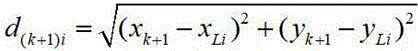
踪目标进行追踪定位。设待追踪目标的初始位置为


其中,


计算声光信号的互相关函数后,通过寻找互相关函数的最大值得到信号匹配最佳
的时刻,即得到目标移动导致的水声信号的相位移改变量
在二维平面内k时刻的坐标


待追踪目标k时刻


而移动的距离差与接收到的水声相移量有关,因此:


本发明实施例提供一种目标追踪方法,通过根据光强信号确定水声相位变化信号,可以利用本申请上述提供的水声探测装置,其采用声光传感方法接收水下待追踪声学目标时,激光束所占用空间较小且激光阵列容易形成,并且激光对声波的高响应带宽,因此不存在随声波频率而变化的接收孔径尺寸问题,在一个相对小的孔径上完成激光布阵,可实现水下目标细节运动的跟踪。An embodiment of the present invention provides a target tracking method. By determining an underwater acoustic phase change signal according to a light intensity signal, the underwater acoustic detection device provided above in this application can be used, which adopts the acousto-optic sensing method to receive the underwater acoustic target to be tracked , the space occupied by the laser beam is small, the laser array is easy to form, and the laser has a high response bandwidth to the sound wave, so there is no problem of the size of the receiving aperture that changes with the frequency of the sound wave. Realize the tracking of underwater target detail movement.
如图10所示,在一个实施例中,提供了一种目标追踪装置,该目标追踪装置可以集成于上述的数据处理装置120中,具体可以包括获取模块410、相位变化确定模块420、以及运动轨迹确定模块430;As shown in FIG. 10 , in one embodiment, a target tracking device is provided. The target tracking device can be integrated into the above-mentioned
获取模块410,用于获取光强信号,所述光强信号为上述的水声探测装置中激光的光强信号;an
相位变化确定模块420,用于根据所述光强信号确定待追踪目标反射的水声信号的相位变化;a phase
运动轨迹确定模块430,用于根据所述水声信号的相位变化确定待追踪目标运动轨迹。The motion
本发明实施例提供一种目标追踪装置,所包含的获取模块410、相位变化确定模块420、以及运动轨迹确定模块430的功能实现与上文目标追踪方法中的步骤S302、步骤S304以及步骤S306一一对应,对于该目标追踪装置中获取模块410、相位变化确定模块420、以及运动轨迹确定模块430的具体解释,以及相关细化、优化的内容参见上文目标追踪方法中的具体实施例,此处不再赘述。An embodiment of the present invention provides a target tracking device, including an
本发明实施例提供的一种目标追踪装置,可以获取上述水声探测装置的光强信号,然后根据光强信号确定待追踪目标反射的水声信号的相位变化,进而根据水声信号的相位变化确定待追踪目标的运动轨迹,其中水声探测装置利用声光效应实现水声探测,有效避免传统声学换能器由机械振动导致的起讫点模糊问题,提高探测精度。A target tracking device provided by an embodiment of the present invention can acquire the light intensity signal of the underwater acoustic detection device, and then determine the phase change of the underwater acoustic signal reflected by the target to be tracked according to the light intensity signal, and then according to the phase change of the underwater acoustic signal The motion trajectory of the target to be tracked is determined, and the underwater acoustic detection device utilizes the acousto-optic effect to realize the underwater acoustic detection, which effectively avoids the blurring of the origin and destination caused by the mechanical vibration of the traditional acoustic transducer, and improves the detection accuracy.
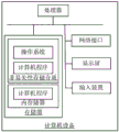
图11示出了一个实施例中计算机设备的内部结构图。该计算机设备具体可以是图6中的数据处理装置120。如图11所示,该计算机设备包括该计算机设备包括通过系统总线连接的处理器、存储器、网络接口、输入装置和显示屏。其中,存储器包括非易失性存储介质和内存储器。该计算机设备的非易失性存储介质存储有操作系统,还可存储有计算机程序,该计算机程序被处理器执行时,可使得处理器实现目标追踪方法。该内存储器中也可储存有计算机程序,该计算机程序被处理器执行时,可使得处理器执行目标追踪方法。计算机设备的显示屏可以是液晶显示屏或者电子墨水显示屏,计算机设备的输入装置可以是显示屏上覆盖的触摸层,也可以是计算机设备外壳上设置的按键、轨迹球或触控板,还可以是外接的键盘、触控板或鼠标等。Figure 11 shows an internal structure diagram of a computer device in one embodiment. The computer equipment may specifically be the
本领域技术人员可以理解,图11中示出的结构,仅仅是与本申请方案相关的部分结构的框图,并不构成对本申请方案所应用于其上的计算机设备的限定,具体的计算机设备可以包括比图中所示更多或更少的部件,或者组合某些部件,或者具有不同的部件布置。Those skilled in the art can understand that the structure shown in FIG. 11 is only a block diagram of a partial structure related to the solution of the present application, and does not constitute a limitation on the computer equipment to which the solution of the present application is applied. Include more or fewer components than shown in the figures, or combine certain components, or have a different arrangement of components.
在一个实施例中,本申请提供的目标追踪装置可以实现为一种计算机程序的形式,计算机程序可在如图11所示的计算机设备上运行。计算机设备的存储器中可存储组成该目标追踪装置的各个程序模块,比如,图10所示的获取模块410、相位变化确定模块420和运动轨迹确定模块430。各个程序模块构成的计算机程序使得处理器执行本说明书中描述的本申请各个实施例的目标方法中的步骤。In one embodiment, the target tracking apparatus provided by the present application can be implemented in the form of a computer program, and the computer program can be executed on the computer device as shown in FIG. 11 . The memory of the computer device may store various program modules constituting the target tracking device, for example, the
例如,图11所示的计算机设备可以通过如图10所示的目标追踪装置中的获取模块410执行步骤S302。计算机设备可通过相位变化确定模块420执行步骤S304。计算机设备可通过运动轨迹确定模块430执行步骤S306。For example, the computer device shown in FIG. 11 may execute step S302 through the acquiring
应该理解的是,虽然本发明各实施例的流程图中的各个步骤按照箭头的指示依次显示,但是这些步骤并不是必然按照箭头指示的顺序依次执行。除非本文中有明确的说明,这些步骤的执行并没有严格的顺序限制,这些步骤可以以其它的顺序执行。而且,各实施例中的至少一部分步骤可以包括多个子步骤或者多个阶段,这些子步骤或者阶段并不必然是在同一时刻执行完成,而是可以在不同的时刻执行,这些子步骤或者阶段的执行顺序也不必然是依次进行,而是可以与其它步骤或者其它步骤的子步骤或者阶段的至少一部分轮流或者交替地执行。It should be understood that although the steps in the flowcharts of the embodiments of the present invention are sequentially displayed in accordance with the arrows, these steps are not necessarily executed in the order indicated by the arrows. Unless explicitly stated herein, the execution of these steps is not strictly limited to the order, and these steps may be performed in other orders. Moreover, at least a part of the steps in each embodiment may include multiple sub-steps or multiple stages. These sub-steps or stages are not necessarily executed and completed at the same time, but may be executed at different times. The order of execution is also not necessarily sequential, but may be performed alternately or alternately with other steps or sub-steps of other steps or at least a portion of a phase.
本领域普通技术人员可以理解实现上述实施例方法中的全部或部分流程,是可以通过计算机程序来指令相关的硬件来完成,所述的程序可存储于一非易失性计算机可读取存储介质中,该程序在执行时,可包括如上述各方法的实施例的流程。其中,本申请所提供的各实施例中所使用的对存储器、存储、数据库或其它介质的任何引用,均可包括非易失性和/或易失性存储器。非易失性存储器可包括只读存储器(ROM)、可编程ROM(PROM)、电可编程ROM(EPROM)、电可擦除可编程ROM(EEPROM)或闪存。易失性存储器可包括随机存取存储器(RAM)或者外部高速缓冲存储器。作为说明而非局限,RAM以多种形式可得,诸如静态RAM(SRAM)、动态RAM(DRAM)、同步DRAM(SDRAM)、双数据率SDRAM(DDRSDRAM)、增强型SDRAM(ESDRAM)、同步链路(Synchlink) DRAM(SLDRAM)、存储器总线(Rambus)直接RAM(RDRAM)、直接存储器总线动态RAM(DRDRAM)、以及存储器总线动态RAM(RDRAM)等。Those of ordinary skill in the art can understand that all or part of the processes in the methods of the above embodiments can be implemented by instructing relevant hardware through a computer program, and the program can be stored in a non-volatile computer-readable storage medium , when the program is executed, it may include the flow of the above-mentioned method embodiments. Wherein, any reference to memory, storage, database or other medium used in the various embodiments provided in this application may include non-volatile and/or volatile memory. Nonvolatile memory may include read only memory (ROM), programmable ROM (PROM), electrically programmable ROM (EPROM), electrically erasable programmable ROM (EEPROM), or flash memory. Volatile memory may include random access memory (RAM) or external cache memory. By way of illustration and not limitation, RAM is available in various forms such as static RAM (SRAM), dynamic RAM (DRAM), synchronous DRAM (SDRAM), double data rate SDRAM (DDRSDRAM), enhanced SDRAM (ESDRAM), synchronous chain Road (Synchlink) DRAM (SLDRAM), memory bus (Rambus) direct RAM (RDRAM), direct memory bus dynamic RAM (DRDRAM), and memory bus dynamic RAM (RDRAM) and so on.
以上所述实施例的各技术特征可以进行任意的组合,为使描述简洁,未对上述实施例中的各个技术特征所有可能的组合都进行描述,然而,只要这些技术特征的组合不存在矛盾,都应当认为是本说明书记载的范围。The technical features of the above-described embodiments can be combined arbitrarily. For the sake of brevity, all possible combinations of the technical features in the above-described embodiments are not described. However, as long as there is no contradiction between the combinations of these technical features, All should be regarded as the scope described in this specification.
以上所述实施例仅表达了本发明的几种实施方式,其描述较为具体和详细,但并不能因此而理解为对本发明专利范围的限制。应当指出的是,对于本领域的普通技术人员来说,在不脱离本发明构思的前提下,还可以做出若干变形和改进,这些都属于本发明的保护范围。因此,本发明专利的保护范围应以所附权利要求为准。The above-mentioned embodiments only represent several embodiments of the present invention, and the descriptions thereof are specific and detailed, but should not be construed as a limitation on the scope of the patent of the present invention. It should be pointed out that for those of ordinary skill in the art, without departing from the concept of the present invention, several modifications and improvements can also be made, which all belong to the protection scope of the present invention. Therefore, the protection scope of the patent of the present invention should be subject to the appended claims.
以上所述仅为本发明的较佳实施例而已,并不用以限制本发明,凡在本发明的精神和原则之内所作的任何修改、等同替换和改进等,均应包含在本发明的保护范围之内。The above descriptions are only preferred embodiments of the present invention and are not intended to limit the present invention. Any modifications, equivalent replacements and improvements made within the spirit and principles of the present invention shall be included in the protection of the present invention. within the range.
Claims (10)
Priority Applications (1)
| Application Number | Priority Date | Filing Date | Title |
|---|---|---|---|
| CN202210217666.7A CN114323250B (en) | 2022-03-08 | 2022-03-08 | Underwater sound detection device, system, target tracking method and device |
Applications Claiming Priority (1)
| Application Number | Priority Date | Filing Date | Title |
|---|---|---|---|
| CN202210217666.7A CN114323250B (en) | 2022-03-08 | 2022-03-08 | Underwater sound detection device, system, target tracking method and device |
Publications (2)
| Publication Number | Publication Date |
|---|---|
| CN114323250A true CN114323250A (en) | 2022-04-12 |
| CN114323250B CN114323250B (en) | 2022-06-14 |
Family
ID=81030157
Family Applications (1)
| Application Number | Title | Priority Date | Filing Date |
|---|---|---|---|
| CN202210217666.7A Active CN114323250B (en) | 2022-03-08 | 2022-03-08 | Underwater sound detection device, system, target tracking method and device |
Country Status (1)
| Country | Link |
|---|---|
| CN (1) | CN114323250B (en) |
Cited By (2)
| Publication number | Priority date | Publication date | Assignee | Title |
|---|---|---|---|---|
| CN114675232A (en) * | 2022-05-26 | 2022-06-28 | 天津大学 | A sound wave direction of arrival detection device, method and computer equipment |
| CN119642956A (en) * | 2025-02-18 | 2025-03-18 | 天津揽海慧听科技有限公司 | Miniaturized laser sound field structure and hydrophone |
Citations (11)
| Publication number | Priority date | Publication date | Assignee | Title |
|---|---|---|---|---|
| US20020167676A1 (en) * | 2001-04-24 | 2002-11-14 | Alain Blouin | Method and apparatus for probing objects in motion |
| CN1547039A (en) * | 2003-12-16 | 2004-11-17 | 中国测绘科学研究院 | Underwater GPS positioning and navigation method and system without high stable frequency standard |
| US20060256650A1 (en) * | 2003-05-02 | 2006-11-16 | Agency For Defense Development | Simulator for developing acoustic detector of underwater vehicle |
| CN101566691A (en) * | 2009-05-11 | 2009-10-28 | 华南理工大学 | Method and system for tracking and positioning underwater target |
| US20180045544A1 (en) * | 2015-07-14 | 2018-02-15 | Lawrence Livermore National Security, Llc | Uv laser based stand-off acoustic sensor |
| CN107748004A (en) * | 2017-11-07 | 2018-03-02 | 天津大学 | A kind of non-contact ultrasonic sound pressure detection device and method |
| CN108445474A (en) * | 2018-02-28 | 2018-08-24 | 天津大学 | A kind of underwater multi-beam echo precision detection method based on acoustooptical effect |
| CN108490422A (en) * | 2018-02-28 | 2018-09-04 | 天津大学 | A kind of underwater simple beam echo precision detection method and system based on acoustooptical effect |
| CN110727282A (en) * | 2019-10-25 | 2020-01-24 | 嘉兴中科声学科技有限公司 | AUV docking method and device and underwater docking system |
| CN112327252A (en) * | 2020-10-12 | 2021-02-05 | 中国海洋大学 | A multi-target tracking method based on multi-speaker and multi-microphone sound waves |
| CN113176539A (en) * | 2021-04-25 | 2021-07-27 | 哈尔滨工程大学 | Underwater sound signal noise multi-stage suppression and steady positioning system and positioning method |
-
2022
- 2022-03-08 CN CN202210217666.7A patent/CN114323250B/en active Active
Patent Citations (11)
| Publication number | Priority date | Publication date | Assignee | Title |
|---|---|---|---|---|
| US20020167676A1 (en) * | 2001-04-24 | 2002-11-14 | Alain Blouin | Method and apparatus for probing objects in motion |
| US20060256650A1 (en) * | 2003-05-02 | 2006-11-16 | Agency For Defense Development | Simulator for developing acoustic detector of underwater vehicle |
| CN1547039A (en) * | 2003-12-16 | 2004-11-17 | 中国测绘科学研究院 | Underwater GPS positioning and navigation method and system without high stable frequency standard |
| CN101566691A (en) * | 2009-05-11 | 2009-10-28 | 华南理工大学 | Method and system for tracking and positioning underwater target |
| US20180045544A1 (en) * | 2015-07-14 | 2018-02-15 | Lawrence Livermore National Security, Llc | Uv laser based stand-off acoustic sensor |
| CN107748004A (en) * | 2017-11-07 | 2018-03-02 | 天津大学 | A kind of non-contact ultrasonic sound pressure detection device and method |
| CN108445474A (en) * | 2018-02-28 | 2018-08-24 | 天津大学 | A kind of underwater multi-beam echo precision detection method based on acoustooptical effect |
| CN108490422A (en) * | 2018-02-28 | 2018-09-04 | 天津大学 | A kind of underwater simple beam echo precision detection method and system based on acoustooptical effect |
| CN110727282A (en) * | 2019-10-25 | 2020-01-24 | 嘉兴中科声学科技有限公司 | AUV docking method and device and underwater docking system |
| CN112327252A (en) * | 2020-10-12 | 2021-02-05 | 中国海洋大学 | A multi-target tracking method based on multi-speaker and multi-microphone sound waves |
| CN113176539A (en) * | 2021-04-25 | 2021-07-27 | 哈尔滨工程大学 | Underwater sound signal noise multi-stage suppression and steady positioning system and positioning method |
Non-Patent Citations (4)
| Title |
|---|
| XUE B等: "《A traceable high-accuracy velocity measurement by electro-optic dual-Comb Interferometry》", 《APPLIED SCIENCES》 * |
| XUE B等: "《A traceable high-accuracy velocity measurement by electro-optic dual-Comb Interferometry》", 《APPLIED SCIENCES》, vol. 9, no. 19, 30 September 2019 (2019-09-30), pages 1 - 8 * |
| 于丙涛等: "《光纤通信在舰艇水下目标跟踪中的应用》", 《舰船科学技术》 * |
| 于丙涛等: "《光纤通信在舰艇水下目标跟踪中的应用》", 《舰船科学技术》, vol. 41, no. 5, 31 May 2019 (2019-05-31), pages 151 - 153 * |
Cited By (3)
| Publication number | Priority date | Publication date | Assignee | Title |
|---|---|---|---|---|
| CN114675232A (en) * | 2022-05-26 | 2022-06-28 | 天津大学 | A sound wave direction of arrival detection device, method and computer equipment |
| CN114675232B (en) * | 2022-05-26 | 2022-08-23 | 天津大学 | Sound wave arrival direction detection device and method and computer equipment |
| CN119642956A (en) * | 2025-02-18 | 2025-03-18 | 天津揽海慧听科技有限公司 | Miniaturized laser sound field structure and hydrophone |
Also Published As
| Publication number | Publication date |
|---|---|
| CN114323250B (en) | 2022-06-14 |
Similar Documents
| Publication | Publication Date | Title |
|---|---|---|
| CN114323250B (en) | Underwater sound detection device, system, target tracking method and device | |
| Zeng et al. | Evaluation of the angular spectrum approach for simulations of near-field pressures | |
| Kniffin et al. | Performance metrics for depth-based signal separation using deep vertical line arrays | |
| US5384573A (en) | Image synthesis using time sequential holography | |
| CN107356320B (en) | A pulsed ultrasonic sound field detection device and method | |
| CN101644773B (en) | Real-time frequency domain super-resolution direction estimation method and device | |
| CN114675232B (en) | Sound wave arrival direction detection device and method and computer equipment | |
| Voskresenskii et al. | Electrooptical Arrays | |
| CN108318123A (en) | A kind of near field sound chromatography test method of underwater acoustic array mutual radiation impedance | |
| Harker et al. | Optimization of the array mirror for time reversal techniques used in a half-space environment | |
| CN109974641A (en) | An acoustic detection device, system, method, computer equipment and storage medium | |
| Boger-Lombard et al. | Towards passive non-line-of-sight acoustic localization around corners using uncontrolled random noise sources | |
| WO2020155142A1 (en) | Point cloud resampling method, device and system | |
| Higgins et al. | Underwater acoustic propagation and scattering from a dynamic rough sea surface using the Finite-Difference Time-Domain method | |
| EP0617797B1 (en) | Image synthesis using time sequential holography | |
| JP2011191250A (en) | Underwater distance measurement system | |
| WO2020237663A1 (en) | Multi-channel lidar point cloud interpolation method and ranging apparatus | |
| WO2024207467A1 (en) | Radar positioning method and apparatus, electronic device and storage medium | |
| US12061288B2 (en) | Aperiodic mirror array for suppressed side lobe intensity | |
| CN212255710U (en) | An acoustic detection device and sound field detection system | |
| Gurbatov et al. | On diffraction of a sawtooth nonlinear wave by a narrow circular aperture in a screen | |
| CN107515051A (en) | Wavelength measurement method and system based on acousto-optic effect | |
| CN114442117A (en) | High-resolution flash lidar imaging system | |
| Wang et al. | Method of merging the divergence sparsity and simplified acousto-optic interferometry to sense an acoustic wave field | |
| CN116559907B (en) | Underwater single photon three-dimensional imaging system based on chaotic laser and quantum correlation detection |
Legal Events
| Date | Code | Title | Description |
|---|---|---|---|
| PB01 | Publication | ||
| PB01 | Publication | ||
| SE01 | Entry into force of request for substantive examination | ||
| SE01 | Entry into force of request for substantive examination | ||
| GR01 | Patent grant | ||
| GR01 | Patent grant |