Detailed Description
Hereinafter, the communication unit of the circuit breaker and the circuit breaker will be described in detail based on the drawings.
Embodiment 1.
Fig. 1 is a diagram showing an example of a relationship between a circuit breaker and a communication unit according to embodiment 1. As shown in fig. 1, a circuit breaker 100 according to embodiment 1 includes: an opening and closing contact 2; an opening/closing mechanism unit 3 for opening/closing the opening/closing contacts 2; and a trip device 4 for causing the opening and closing mechanism unit 3 to perform a trip operation.
The opening/closing contact 2 includes a movable contact and a fixed contact, and the movable contact and the fixed contact are brought into contact with and separated from each other by the opening/closing mechanism 3. When the movable contact contacts the fixed contact, the opening/closing contact 2 is closed, and the electric circuit 5 is closed. When the movable contact and the fixed contact are separated from each other, the opening/closing contact 2 is opened, and the electric circuit 5 is opened. The circuit 5 shown in fig. 1 is a circuit 5 having U-phase, V-phase, and W-phase1、52、53But may be a single phase circuit or other circuits.
The circuit breaker 100 is formed with a housing area 6, and the communication unit 1 is detachably disposed in the housing area 6. When the state of the circuit breaker 100 changes, the communication unit 1 transmits state information indicating the state of the circuit breaker 100 to an external device through wireless communication. The state of the circuit breaker 100 is any of an open state, an on state, and a tripped state.
The communication unit 1 is 1 of a plurality of types of cassette attachments detachably attached to the housing area 6 of the circuit breaker 100. In the box accessory, in addition to the communication unit 1, there are an auxiliary switch, an alarm switch, a voltage trip device, or the like.
Thus, if the circuit breaker 100 is provided with the housing area 6 in which the cassette attachment is detachably disposed, the communication unit 1 can provide the circuit breaker 100 with the wireless communication function regardless of the existing circuit breaker 100 or the newly installed circuit breaker 100.
The auxiliary switch is a box accessory device including a switch for electrically outputting information indicating the open/close state of the open/close contact 2. The alarm switch is a box accessory device including a switch for electrically outputting information indicating the presence or absence of a trip state of the circuit breaker 100. The voltage trip device is a box accessory device for electrically tripping the circuit breaker 100 from a remote location.
The communication unit 1 is not limited to the box accessory device, and may be configured to be non-detachably incorporated in the circuit breaker 100, or may be configured to be detachably disposed in a dedicated area different from the storage area 6 detachably disposed in the auxiliary switch, the alarm switch, the voltage trip device, or the like.
The circuit breaker 100 is provided between a power supply device and a load device. The trip device 4 of the circuit breaker 100 causes the opening/closing mechanism portion 3 to perform a tripping operation for changing the state of the opening/closing contact 2 from a closed state to an open state when a current flowing through the electric circuit 5 between the power supply device and the load device satisfies a predetermined condition. Thereby, the state of the circuit breaker 100 becomes the tripped state.
For example, when the circuit breaker 100 is a wiring circuit breaker, the trip device 4 causes the opening/closing mechanism 3 to perform a trip operation for changing the state of the opening/closing contact 2 from a closed state to an open state when an overcurrent or a short-circuit current flows through the circuit 5. When the circuit breaker 100 is an earth leakage circuit breaker, the trip device 4 causes the opening/closing mechanism 3 to perform a tripping operation for changing the state of the opening/closing contact 2 from a closed state to an open state when an overcurrent, a short-circuit current, or a leakage current flows through the circuit 5.
The state of the circuit breaker 100 is changed from the on state to the off state when the state of the opening/closing contact 2 is changed from the closed state to the open state by the opening/closing mechanism unit 3, and is changed from the off state to the on state when the state of the opening/closing contact 2 is changed from the open state to the closed state by the opening/closing mechanism unit 3. When the circuit breaker 100 is in the on state, the opening/closing mechanism unit 3 brings the state of the opening/closing contact 2 into the closed state, and when the circuit breaker 100 is in the off state, the opening/closing mechanism unit 3 brings the state of the opening/closing contact 2 into the open state.
Fig. 2 is a block diagram of a communication unit according to embodiment 1. The communication unit 1 shown in fig. 2 includes an environment power generating element 10, a rectifier circuit 11, a dc/dc converter 12, a wireless communication unit 13, a trip detection switch 14, an open/close detection switch 15, substrates 18 and 19, and actuators 20 and 21. The environment power generation element 10, the rectifier circuit 11, the dc/dc converter 12, and the wireless communication unit 13 are mounted on a substrate 18, and the trip detection switch 14 and the open/close detection switch 15 are mounted on a substrate 19.
The environment power generation element 10 is an element that generates electric power in an environment called energy collection, and obtains relatively small mechanical energy from the surrounding environment and converts the mechanical energy into electric energy. Specifically, the environment power generation element 10 is an element that converts mechanical energy generated in the opening/closing mechanism unit 3 into electrical energy, and converts mechanical displacement or vibration generated when the state of the circuit breaker 100 changes into electrical energy. For example, the environment power generation element 10 may be an element that obtains electric energy by electromagnetically inducing mechanical displacement, or may be an element that obtains electric energy from vibration by a piezoelectric element.
The rectifying circuit 11 rectifies the voltage output from the environment power generating element 10. Thus, even when the voltages are different in the positive and negative directions according to the direction in which the state of the circuit breaker 100 changes, the environment power generation element 10 can output a positive voltage from the rectifier circuit 11 to the dc/dc converter 12. The direction of the state change of the circuit breaker 100 includes, for example, a direction of changing from an off state or a tripped state to an on state, and a direction of changing from an on state to an off state or a tripped state.
The dc/dc converter 12 converts the voltage rectified by the rectifier circuit 11 into a predetermined voltage, and outputs the converted voltage as a power supply voltage of the wireless communication unit 13.
The wireless communication unit 13 is supplied with the generated power of the environment power generation element 10 through the rectifier circuit 11 and the dc/dc converter 12, and operates. The wireless communication unit 13 determines the state of the circuit breaker 100 based on the states of the trip detection switch 14 and the open/close detection switch 15, and transmits state information indicating the determined state of the circuit breaker 100 to an external device through wireless communication. The wireless communication unit 13 corresponds to, for example, a short-range wireless communication system such as BLE (registered trademark) or a wireless lan (local Area network) communication system such as Wi-Fi (registered trademark), but may be configured to transmit the status information by a wireless communication system other than these wireless communication systems.
The state of the trip detection switch 14 is an on state when the state of the circuit breaker 100 is not a tripped state, and is an off state when the state of the circuit breaker 100 is a tripped state. The state of the opening/closing detection switch 15 is an off state when the circuit breaker 100 is in an on state, and is an on state when the circuit breaker 100 is in an off state or a tripped state.
Fig. 3 is a diagram showing a relationship among a state of a trip detection switch, a state of an open/close detection switch, and a state of a circuit breaker according to embodiment 1. As shown in fig. 3, when the trip detection switch 14 is in the on state and the open/close detection switch 15 is in the off state, the state of the circuit breaker 100 is in the on state. When the trip detection switch 14 is in the off state and the opening/closing detection switch 15 is in the on state, the state of the circuit breaker 100 is the tripped state.
When the trip detection switch 14 is in the on state and the opening/closing detection switch 15 is in the on state, the circuit breaker 100 is in the off state. In the circuit breaker 100, the trip detection switch 14 and the opening/closing detection switch 15 are not both in the off state.
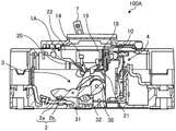
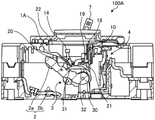
Fig. 4 is a diagram showing an internal configuration in a case where the circuit breaker according to embodiment 1 is in an on state, fig. 5 is a diagram showing an internal configuration in a case where the circuit breaker according to embodiment 1 is in a trip state, and fig. 6 is a diagram showing an internal configuration in a case where the circuit breaker according to embodiment 1 is in an off state.
As shown in fig. 4 to 6, the circuit breaker 100 includes a communication unit 1, an opening/closing contact 2, an opening/closing mechanism portion 3, and a trip device 4. The opening/closing contact 2 includes a movable contact 2a and a fixed contact 2 b. The opening/closing mechanism portion 3 has a movable contact 30, a trip lever 31, and a crossbar 32. A movable contact 2a is attached to a distal end portion of the movable contact 30. The base end portion of the movable contact 30 is rotatably attached to the crossbar 32 around the axial center of the crossbar 32.
The trip lever 31 is driven by the trip device 4 when a current flowing in the electric circuit 5 between the power supply device and the load device satisfies a predetermined condition. When the trip lever 31 is driven, the opening/closing mechanism 3 is tripped by the action of the trip lever 31, the state of the opening/closing contact 2 is changed from the closed state to the open state, and the circuit breaker 100 is changed from the closed state to the tripped state.
In circuit breaker 100 for circuit 5 shown in fig. 11、52、53Provided with movable contacts 30, respectively, and a crossbar 32 mounted for each circuit 51、52、53A movable contact 30 is provided. The crossbar 32 rotates about its axial center, and the movable contact 30 rotates to make contact with and separate from the movable contact 2a and the fixed contact 2 b. The handle 7 provided in the circuit breaker 100 is coupled to the crossbar 32 via, for example, a handle arm not shown, and the crossbar 32 rotates in accordance with the rotation of the handle 7. The handle 7 is biased by a main spring, not shown, whose biasing direction changes according to the rotational direction of the handle 7.
As shown in fig. 4 to 6, the communication unit 1 includes an environment power generating element 10, a trip detection switch 14, an open/close detection switch 15, substrates 18 and 19, actuators 20 and 21, and a housing 22. The substrates 18 and 19 and the actuators 20 and 21 are rotatably supported by a frame 22. When the communication unit 1 is a box attachment, the housing 22 is a case of the box attachment. In fig. 4 to 6, the rectifier circuit 11, the dc/dc converter 12, and the wireless communication unit 13 are not shown. Actuator 21 is an example of the 1 st actuator, and actuator 20 is an example of the 2 nd actuator.
The actuator 20 is rotatably supported at a middle portion thereof by the housing 22 of the communication unit 1, and has one end disposed at a position facing the trip lever 31 and the other end disposed at a position facing the trip detection switch 14. The actuator 20 presses the trip detection switch 14 when the state of the circuit breaker 100 is the on state. Therefore, when the state of the circuit breaker 100 is the on state, the trip detection switch 14 is in the on state.
When the circuit breaker 100 is tripped, the actuator 20 has one end pressed by the trip lever 31 and rotates counterclockwise in fig. 4 about the middle portion thereof, and the other end separated from the trip detection switch 14. Thereby, the state of the trip detection switch 14 is changed from the on state to the off state.
The actuator 21 operates in accordance with the opening and closing operation of the opening and closing contact 2 by the opening and closing mechanism unit 3. The actuator 21 is rotatably supported at a middle portion thereof by the housing 22 of the communication unit 1, and has one end disposed at a position facing the crossbar 32 and the other end disposed at a position facing the open/close detection switch 15. The other end of the actuator 21 is positioned so as not to press the opening/closing detection switch 15 when the circuit breaker 100 is in the on state. Therefore, when the circuit breaker 100 is in the on state, the opening/closing detection switch 15 is in the off state.
When the state of the circuit breaker 100 is changed from the on state shown in fig. 4 to the off state shown in fig. 6 by operating the opening/closing mechanism portion 3 by the operation of the handle 7 of the user, the crossbar 32 of the opening/closing mechanism portion 3 rotates clockwise in fig. 4 when the state of the circuit breaker 100 is changed from the on state to the off state. As a result, as shown in fig. 6, the crossbar 32 presses the opening/closing detection switch 15, and the state of the opening/closing detection switch 15 is changed from the off state to the on state. Similarly, when the circuit breaker 100 is in the trip operation, the crossbar 32 of the opening/closing mechanism unit 3 rotates clockwise in fig. 4, the crossbar 32 presses the opening/closing detection switch 15, and the state of the opening/closing detection switch 15 changes from the off state to the on state.
When the state of the circuit breaker 100 is the off state shown in fig. 6, when the opening/closing mechanism portion 3 is operated by the operation of the handle 7 of the user and the state of the circuit breaker 100 is changed from the off state to the on state, the crossbar 32 of the opening/closing mechanism portion 3 rotates counterclockwise in fig. 6. As a result, as shown in fig. 4, the crossbar 32 is separated from the open/close detection switch 15, and the open/close detection switch 15 is switched from the on state to the off state.
The environment electricity generating element 10 is driven by an actuator 21. Specifically, the environment power generation element 10 is driven by the actuator 21 that rotates when the state of the circuit breaker 100 changes, and generates power. The opening/closing mechanism 3 is provided with the main spring described above, and the amount of power generated by the environment power generation element 10 can be increased by driving the actuator 21 by the biasing force of the main spring. The wireless communication unit 13 of the communication unit 1 operates by the power generated by the environment power generation element 10, determines the state of the circuit breaker 100 based on the states of the trip detection switch 14 and the open/close detection switch 15, and transmits state information indicating the determined state of the circuit breaker 100 to an external device through wireless communication.
For example, the environment power generation element 10 is driven by the actuator 21 that rotates by the biasing force of the main spring when the state of the circuit breaker 100 changes from the off state to the on state, and generates power. In this case, the wireless communication unit 13 of the communication unit 1 operates by the power generated by the environment power generation element 10, and determines that the state of the circuit breaker 100 is the on state based on the states of the trip detection switch 14 and the open/close detection switch 15. The wireless communication unit 13 transmits state information indicating that the state of the circuit breaker 100 is in the on state to an external device by wireless communication.
The environment power generation element 10 is driven by an actuator 21 that is rotated by the biasing force of the main spring when the state of the circuit breaker 100 changes from the on state to the off state, and generates power. In this case, the wireless communication unit 13 of the communication unit 1 operates by the power generated by the environment power generation element 10, and determines that the state of the circuit breaker 100 is the open state based on the states of the trip detection switch 14 and the open/close detection switch 15. The wireless communication unit 13 transmits state information indicating that the state of the circuit breaker 100 is in the open state to an external device through wireless communication.
The environment power generation element 10 is driven by an actuator 21 that is rotated by the biasing force of the main spring when the state of the circuit breaker 100 changes from the on state to the off state, and generates power. In this case, the wireless communication unit 13 of the communication unit 1 operates by the power generated by the environment power generation element 10, and determines that the state of the circuit breaker 100 is the tripped state based on the states of the trip detection switch 14 and the open/close detection switch 15. The wireless communication unit 13 transmits state information indicating that the state of the circuit breaker 100 is in the tripped state to an external device through wireless communication.
The power generation of the environment power generation element 10 by the actuator 21 is performed when the environment power generation element 10 is pressed by the actuator 21, and is performed when the pressing of the environment power generation element 10 by the actuator 21 is released.
Fig. 7 is a diagram showing an example of the relationship between the actuator, the open/close detection switch, and the environment power generating element according to embodiment 1. As shown in fig. 7, when the state of the circuit breaker 100 is the on state, the environment power generation element 10 is in a state not pressed by the actuator 21. When the state of the circuit breaker 100 changes from the on state to the off state or the tripped state, the actuator 21 presses the environment power generation element 10, and the environment power generation element 10 generates power.
When the state of the circuit breaker 100 is changed from the off state or the tripped state to the on state, the environment power generation element 10 is pressed by the actuator 21 to be not pressed, and the environment power generation element 10 generates power.
As described above, the environment power generation element 10 generates power when the pressing by the actuator 21 is released and when the pressing by the actuator 21 is released. The environment power generating element 10 outputs a voltage having different positive and negative values between the case where the pressing by the actuator 21 is performed and the case where the pressing by the actuator 21 is released, but may output a voltage having the same positive and negative values in any case.
The period during which the wireless communication unit 13 operates by the power generated by the environment power generation element 10 when the state of the circuit breaker 100 changes is longer than a predetermined period. The predetermined period is a period from the start of the supply of power to the wireless communication unit 13 through the environment power generating element 10 to the time when the wireless communication unit 13 outputs the state information through wireless communication.
As described above, the communication unit 1 of the circuit breaker 100 transmits the state information indicating the state of the circuit breaker 100 to the external device through wireless communication using the power generated by the environment power generation element 10 when the state of the circuit breaker 100 changes. Therefore, the communication unit 1 can output the state information indicating the state of the circuit breaker 100 by wireless communication without using the power of the power supply circuit that generates the power supply voltage from the current flowing through the circuit 5 or the power of the 1-time battery.
Next, a process performed by the wireless communication unit 13 of the communication unit 1 will be described with reference to a flowchart. Fig. 8 is a flowchart showing an example of processing performed by the wireless communication module of the communication unit according to embodiment 1. The processing shown in fig. 8 is performed after the wireless communication unit 13 is activated by the generated power from the environment power generating element 10.
As shown in fig. 8, the wireless communication unit 13 detects the state of the trip detection switch 14 (step S10). The wireless communication unit 13 also detects the state of the open/close detection switch 15 (step S11). The wireless communication unit 13 determines the state of the circuit breaker 100 based on the state of the trip detection switch 14 detected in step S10 and the state of the open/close detection switch 15 detected in step S11 (step S12).
Then, the wireless communication unit 13 outputs the state information indicating the state of the circuit breaker 100 determined in step S12 to the external device through wireless communication (step S13), and the process shown in fig. 8 is ended.
In the above example, the example in which the number of the environment power generation elements 10 in the circuit breaker 100 is 1 has been described, but the circuit breaker 100 may have a configuration in which a plurality of environment power generation elements 10 are provided. For example, the circuit breaker 100 may be configured to include the environment power generating element 10 driven by the actuator 20 as the 2 nd environment power generating element in addition to the environment power generating element 10 driven by the actuator 21. In this case, the circuit breaker 100 is provided with a rectifier circuit 11 for rectifying the voltage of the 2 nd environment power generation element driven by the actuator 20 in addition to the rectifier circuit 11 for rectifying the voltage of the environment power generation element 10 driven by the actuator 21. The actuator 20 is biased by a spring, not shown, for example, and the 2 nd environment power generation element can be driven by the actuator 20 rotated by the biasing force of the spring to generate power.
In the above example, the communication unit 1 outputs the state information indicating the state of the circuit breaker 100 by wireless communication, but may be configured to output the state indicating the states of the trip detection switch 14 and the open/close detection switch 15 as the state information by wireless communication. That is, the communication unit 1 may be configured to transmit information directly or indirectly indicating the state of the circuit breaker 100 as state information. The communication unit 1 may transmit information indicating 1 or 2 of the open state, the closed state, and the tripped state of the circuit breaker 100 as the state information.
As described above, the communication unit 1 of the circuit breaker 100 according to embodiment 1 includes the actuator 21, the environment power generating element 10, and the wireless communication unit 13. The actuator 21 operates in accordance with the opening/closing operation of the opening/closing contact 2 by the opening/closing mechanism 3 that opens and closes the opening/closing contact 2. When the actuator 21 is operated, the environment power generation element 10 is driven by the actuator 21 to generate power. The wireless communication unit 13 receives the generated power supplied to the environment power generation element 10, and transmits state information including information indicating the state of the circuit breaker 100. Thus, the communication unit 1 can output information indicating the state of the circuit breaker 100 by wireless communication without using power from the power supply circuit flowing through the circuit 5 or power from the 1-time battery.
The communication unit 1 further includes an open/close detection switch 15, and the open/close detection switch 15 is driven by the actuator 21 when the actuator 21 is operated, and detects the open/close state of the open/close contacts 2. The wireless communication unit 13 transmits state information including information indicating the state of the opening/closing contact 2 as the state of the circuit breaker 100 based on the detection result of the opening/closing detection switch 15. Thus, the communication unit 1 can detect the open/close state of the open/close contact 2 in accordance with the operation of the actuator 21 used for the power generation of the environment power generating element 10 as the state of the circuit breaker 100, and can share the actuator 21 in the power generation of the environment power generating element 10 and the detection of the open/close state of the open/close contact 2.
The environment power generation element 10 generates power when pressed by the actuator 21 and when the pressing by the actuator 21 is released. Thus, the communication unit 1 can generate power by the environment power generating element 10 when the opening/closing contact 2 changes from the closed state to the open state and when the opening/closing contact 2 changes from the open state to the closed state, respectively, and therefore, it is possible to detect the change of the opening/closing contact 2 from the closed state to the open state and the change of the opening/closing contact 2 from the open state to the closed state.
In addition, the communication unit 1 includes: a rectifier circuit 11 that rectifies the electric power output from the environment power generation element 10; and a dc-dc converter 12 that converts the voltage output from the rectifier circuit 11 into a predetermined voltage. The environment power generation element 10 outputs a voltage having a different positive or negative voltage between the case where the pressing by the actuator 21 is released and the case where the pressing by the actuator 21 is released. The wireless communication unit 13 operates by electric power supplied from the environment power generation element 10 through the rectifier circuit 11 and the dc/dc converter 12. Thus, the communication unit 1 can operate the wireless communication unit 13 even when the positive and negative voltages of the voltage output from the environment power generating element 10 are different between the case of being pressed by the actuator 21 and the case of being released from the pressing by the actuator 21.
The communication unit 1 includes an actuator 20 as a 2 nd actuator, and the actuator 20 operates in accordance with a trip operation of the circuit breaker 100 when the actuator 21 is the 1 st actuator. The communication unit 1 further includes a trip detection switch 14, and the trip detection switch 14 is driven by the actuator 20 to detect a trip operation when the actuator 20 is operated. The wireless communication unit 13 determines the presence or absence of a trip operation as the state of the circuit breaker 100 based on the detection result of the trip detection switch 14. The status information includes information indicating the presence or absence of the trip operation determined by the wireless communication unit 13. Thus, the communication unit 1 can output status information including information indicating the presence or absence of a trip operation. The communication unit 1 may be configured without the actuator 20. In this case, the status information does not include information indicating the presence or absence of the trip operation.
Embodiment 2.
The communication unit of the circuit breaker according to embodiment 2 is different from the communication unit 1 of the circuit breaker 100 according to embodiment 1 in that the determination of the state of the open/close contacts is performed based on the positive and negative voltages output from the environment power generation element instead of the open/close detection switch. Hereinafter, the same reference numerals are used to designate components having the same functions as those of embodiment 1, and the description thereof will be omitted, and the differences from communication unit 1 of embodiment 1 will be mainly described.
Fig. 9 is a block diagram of a communication unit according to embodiment 2. The communication unit 1A shown in fig. 9 is different from the communication unit 1 in that it does not have the open/close detection switch 15, has the voltage determination circuit 23, and has the wireless communication unit 13A instead of the wireless communication unit 13.
The voltage determination circuit 23 accumulates a part of the electric power output from the environment power generation element 10 and temporarily holds a positive voltage when the voltage output from the environment power generation element 10 is positive, and does not accumulate the electric power output from the environment power generation element 10 when the voltage output from the environment power generation element 10 is negative. The wireless communication unit 13A determines the state of the open/close contact 2 based on the voltage temporarily held in the voltage determination circuit 23.
The environment power generation element 10 outputs a positive voltage when the state of the opening/closing contact 2 changes from the closed state to the open state. When the voltage held by the voltage determination circuit 23 is greater than or equal to a predetermined value, the wireless communication unit 13A determines that the state of the opening/closing contact 2 is changed from the closed state to the open state. When the voltage held by the voltage determination circuit 23 is smaller than a predetermined value, the wireless communication unit 13A determines that the state of the opening/closing contact 2 is changed from the open state to the closed state.
The environment power generation element 10 may be configured to output a positive voltage when the state of the opening/closing contact 2 changes from the open state to the closed state. In this case, the wireless communication unit 13A determines that the state of the open/close contact 2 is changed from the open state to the closed state when the voltage held in the voltage determination circuit 23 is greater than or equal to a predetermined value. When the voltage held in the voltage determination circuit 23 is smaller than a predetermined value, the wireless communication unit 13A determines that the state of the opening/closing contact 2 is changed from the closed state to the open state.
When the state of the trip detection switch 14 is changed from the on state to the off state, the wireless communication unit 13A determines that the state of the circuit breaker 100 is the tripped state if it is determined that the state of the opening and closing contacts 2 is changed from the closed state to the open state based on the voltage of the voltage determination circuit 23. Further, when the state of the trip detection switch 14 is kept in the on state, the wireless communication unit 13A determines that the state of the circuit breaker 100 is in the off state if it is determined that the state of the opening/closing contacts 2 is changed from the closed state to the open state based on the voltage of the voltage determination circuit 23. When it is determined that the state of the opening/closing contact 2 is changed from the open state to the closed state based on the voltage of the voltage determination circuit 23, the wireless communication unit 13A determines that the state of the circuit breaker 100 is changed to the closed state.
Fig. 10 is a diagram showing an internal configuration in a case where the circuit breaker according to embodiment 2 is in an on state, fig. 11 is a diagram showing an internal configuration in a case where the circuit breaker according to embodiment 2 is in a trip state, and fig. 12 is a diagram showing an internal configuration in a case where the circuit breaker according to embodiment 2 is in an off state. As shown in fig. 10 to 12, the communication unit 1A of the circuit breaker 100A is not provided with the opening/closing detection switch 15.
Fig. 13 is a diagram showing an example of an electric circuit in the communication unit according to embodiment 2. The communication unit 1A shown in fig. 13 is different from the communication unit 1 in that it includes a voltage determination circuit 23.
In the communication unit 1A, the positive-side input terminal of the rectifier circuit 11 is connected to the positive-side terminal of the environment power generation element 10, and the negative-side input terminal of the rectifier circuit 11 is connected to the negative-side terminal of the environment power generation element 10. The positive side output terminal of the rectifying circuit 11 is connected to the input terminal of the dc/dc converter 12, and the negative side output terminal of the rectifying circuit 11 is connected to ground.
Dc-dc converter 12 includes converter 12a and capacitors C2 and C3. The capacitor C2 is connected between the input terminal of the converter 12a and the ground, and accumulates the electric charge output from the rectifier circuit 11. The converter 12a converts the voltage of the capacitor C2 to a predetermined voltage and outputs the voltage. Capacitor C3 is connected between the output terminal of converter 12a and ground.
The voltage determination circuit 23 is a parallel circuit in which a series circuit of a capacitor C1 and resistors R1 and R2 are connected in parallel. The voltage determination circuit 23 is connected between the positive-side terminal of the environment power generation element 10 and the negative-side output terminal of the rectifier circuit 11. Therefore, when the voltage output from the environment power generating element 10 due to the power generation of the environment power generating element 10 is positive, the voltage of the environment power generating element 10 is applied to the capacitor C1 via the diode, and the charge is accumulated in the capacitor C1. When the voltage output from the environment power generating element 10 due to the power generation of the environment power generating element 10 is negative, the voltage of the environment power generating element 10 is not applied to the capacitor C1.
After the power generation of the environment power generating element 10 is completed, the electric charge of the capacitor C1 is discharged through the resistors R1 and R2. The time constant of the voltage determination circuit 23 is set based on the time Ta. The time Ta is a time required for the wireless communication unit 13A to transmit the state information to the external device by wireless communication in order to use the power generated by the environment power generating element 10 after the start of power generation by the environment power generating element 10.
For example, the time constant of the voltage determination circuit 23 is set so that the time until the voltage between the resistor R1 and the resistor R2 becomes equal to or greater than the threshold voltage V1 becomes equal to or greater than the time Ta after the start of power generation of the environment power generating element 10.
Since the environment power generation element 10 outputs a positive voltage when the state of the opening/closing contact 2 changes from the closed state to the open state, the wireless communication unit 13A determines that the state of the opening/closing contact 2 changes from the closed state to the open state if the voltage between the resistor R1 and the resistor R2 is equal to or greater than the threshold voltage V1. Further, the wireless communication unit 13A determines that the state of the open/close contact 2 is changed from the open state to the closed state if the voltage between the resistor R1 and the resistor R2 is smaller than the threshold voltage V1.
The environment power generation element 10 may be configured to output a positive voltage when the state of the opening/closing contact 2 changes from the open state to the closed state. In this case, if the voltage between the resistor R1 and the resistor R2 is equal to or higher than the threshold voltage V1, the wireless communication unit 13A determines that the state of the opening/closing contact 2 is changed from the open state to the closed state. Further, the wireless communication unit 13A determines that the state of the open/close contact 2 is changed from the closed state to the open state if the voltage between the resistor R1 and the resistor R2 is smaller than the threshold voltage V1.
Next, a process performed by the wireless communication unit 13A of the communication unit 1A will be described with reference to a flowchart. Fig. 14 is a flowchart showing an example of processing performed by the wireless communication module of the communication unit according to embodiment 2. The processing shown in fig. 14 is performed after the wireless communication unit 13A is activated by the generated power of the environment power generating element 10.
As shown in fig. 14, the wireless communication unit 13A detects the state of the trip detection switch 14 (step S20). The wireless communication unit 13A detects the voltage of the voltage determination circuit 23 (step S21). The wireless communication unit 13A determines the state of the circuit breaker 100A based on the state of the trip detection switch 14 detected in step S20 and the voltage of the voltage determination circuit 23 detected in step S21 (step S22).
Then, the wireless communication unit 13A outputs the state information indicating the state of the circuit breaker 100A determined in step S22 to an external device through wireless communication (step S23), and the process shown in fig. 14 is ended.
As described above, in the communication unit 1A of the circuit breaker 100A according to embodiment 2, the environment power generating element 10 generates power when the pressing by the actuator 21 is released and when the pressing by the actuator 21 is released, and the positive and negative of the output voltage are different between the pressing by the actuator 21 and the releasing of the pressing by the actuator 21. The wireless communication unit 13A determines the state of the open/close contact 2 based on the positive and negative voltages output from the environment power generation element 10. Thus, the communication unit 1A can determine the state of the opening/closing contact 2 without providing the opening/closing detection switch 15.
The opening/closing contact 2 of the circuit breakers 100 and 100A is a so-called one-touch structure in which the movable contact 2a and the fixed contact 2b are each formed of 1 piece, and the opening/closing contact 2 may be a so-called two-touch structure in which the movable contact 2a and the fixed contact 2b are each formed of 2 pieces. In this case, for example, the opening/closing mechanism portion 3 may have a rotary shaft in the middle of the movable contact 30, the movable contacts 2a may be fixed to one end and the other end of the movable contact 30, and the 2 fixed contacts 2b may be arranged to be able to contact with and separate from the corresponding movable contacts 2a among the 2 movable contacts 2 a.
The circuit breakers 100 and 100A described above are the environment power generation element 10 that generates power by being driven by the actuator 21 that is rotated by the biasing force of the main spring, but the present invention is not limited to this example. For example, the circuit breakers 100 and 100A may be configured such that, when the state changes, the actuator 21 is rotated by a biasing force other than a main spring or a force other than the biasing force, and the environment power generation element 10 is driven by the actuator 21 to generate power.
The configurations described in the above embodiments are only examples of the contents of the present invention, and may be combined with other known techniques, or the embodiments may be combined with each other, and some of the configurations may be omitted or modified without departing from the scope of the present invention.
Description of the reference numerals
1. 1A communication unit, 2 open/close contacts, 2a movable contact, 2b fixed contact, 3 open/close mechanism part, 4 trip device, 51、52、53A circuit, a 6 storage area, a 7 handle, a 10 environment power generation element, an 11 rectification circuit, a 12 DC converter, a 12a conversion part, a 13, 13A wireless communication part, a 14 tripping detection switch, a 15 opening and closing detection switch, a 18, 19 substrate, a 20, 21 actuator, a 22 frame, a 23 voltage determination circuit, a 30 movable contact,31 trip bar, 32 cross bar, 100A circuit breaker.