CN114087163B - Compressor assembly and vehicle with same - Google Patents
Compressor assembly and vehicle with same Download PDFInfo
- Publication number
- CN114087163B CN114087163B CN202010865185.8A CN202010865185A CN114087163B CN 114087163 B CN114087163 B CN 114087163B CN 202010865185 A CN202010865185 A CN 202010865185A CN 114087163 B CN114087163 B CN 114087163B
- Authority
- CN
- China
- Prior art keywords
- compressor assembly
- liquid
- chamber
- ptc heater
- control device
- Prior art date
- Legal status (The legal status is an assumption and is not a legal conclusion. Google has not performed a legal analysis and makes no representation as to the accuracy of the status listed.)
- Active
Links
Images


Classifications
-
- F—MECHANICAL ENGINEERING; LIGHTING; HEATING; WEAPONS; BLASTING
- F04—POSITIVE - DISPLACEMENT MACHINES FOR LIQUIDS; PUMPS FOR LIQUIDS OR ELASTIC FLUIDS
- F04B—POSITIVE-DISPLACEMENT MACHINES FOR LIQUIDS; PUMPS
- F04B39/00—Component parts, details, or accessories, of pumps or pumping systems specially adapted for elastic fluids, not otherwise provided for in, or of interest apart from, groups F04B25/00 - F04B37/00
- F04B39/06—Cooling; Heating; Prevention of freezing
Landscapes
- Engineering & Computer Science (AREA)
- Mechanical Engineering (AREA)
- General Engineering & Computer Science (AREA)
- Compressor (AREA)
Abstract
本发明公开了一种压缩机组件和具有其的车辆,所述压缩机组件包括:机壳,所述机壳包括本体部和端盖部,所述本体部和所述端盖部配合限定出放置腔,所述端盖部上设有与所述放置腔间隔设置的盛液腔;压缩部件,所述压缩部件设在所述放置腔内;PTC加热器,所述PTC加热器设在所述盛液腔内以对所述盛液腔内的液体进行加热。根据本发明实施例的压缩机组件能够在高低温工况下实现快速正常启动,且具有成本低、能耗小、使用寿命长等优点。

The invention discloses a compressor assembly and a vehicle thereof. The compressor assembly includes: a casing, the casing includes a body part and an end cover part, and the body part and the end cover part cooperate to define a Placement chamber, the end cap part is provided with a liquid holding chamber spaced apart from the placement chamber; a compression part, the compression part is arranged in the placement chamber; a PTC heater, the PTC heater is arranged in the placement chamber the liquid in the liquid chamber to heat the liquid in the liquid chamber. The compressor assembly according to the embodiment of the present invention can realize fast and normal startup under high and low temperature conditions, and has the advantages of low cost, low energy consumption, and long service life.
Description
技术领域technical field
本发明涉及压缩机技术领域,尤其是涉及一种压缩机组件和具有其的车辆The invention relates to the technical field of compressors, in particular to a compressor assembly and a vehicle with it
背景技术Background technique
相关技术中的压缩机组件,通常包括压缩部件,压缩部件运行压缩冷媒产生压差,将吸气口吸入的低压低温气态冷媒压缩为高压高温气态冷媒从排气口排出,形成冷媒的物理转换和流动。The compressor assembly in the related art usually includes a compression component. The compression component operates to compress the refrigerant to generate a pressure difference, compress the low-pressure and low-temperature gaseous refrigerant sucked into the suction port into a high-pressure and high-temperature gaseous refrigerant, and discharge it from the exhaust port to form a physical conversion of the refrigerant and flow.
压缩机组件在夏天工作时,由于环境温度较高,压缩部件压缩气体时的做工增多,导致压缩部件的温度较高(例如,超过80℃),排气压力较大,进而造成压缩部件内部压差过大,增加了电机发生失步而停机的几率。压缩机组件停机后,需要消除压缩部件内的静差,压缩机组件才能再次启动,消除静差的时间较长,在等待静差消除的时间内,空调会停止工作,降低用户舒适性。压缩机组件停机后,未消除压缩部件的静差而启动压缩机组件,则存在超出压缩机组件中的功率器件(例如,IGBT(Insulated Gate Bipolar Transistor,绝缘栅双极型晶体管))带载能力的风险,会造成功率器件损坏或减少功率器件的寿命。因此为了解决上述问题,一些压缩机组件通常增大功率器件的余量,但是这样会增加生产成本。When the compressor assembly is working in summer, due to the high ambient temperature, the work of the compression part is increased when the gas is compressed, resulting in a high temperature of the compression part (for example, exceeding 80 ° C), and a large discharge pressure, which in turn causes the internal pressure of the compression part. If the difference is too large, the probability of motor out-of-step and shutdown will be increased. After the compressor assembly is shut down, the static difference in the compression parts needs to be eliminated before the compressor assembly can be restarted. It takes a long time to eliminate the static difference. During the waiting time for the static difference to be eliminated, the air conditioner will stop working, reducing user comfort. After the compressor assembly stops, if the static difference of the compression parts is not eliminated and the compressor assembly is started, the load capacity of the power device (for example, IGBT (Insulated Gate Bipolar Transistor, Insulated Gate Bipolar Transistor, Insulated Gate Bipolar Transistor)) in the compressor assembly will be exceeded The risk will cause damage to power devices or reduce the life of power devices. Therefore, in order to solve the above problems, some compressor components usually increase the margin of power devices, but this will increase the production cost.
另外,压缩机组件在冬天工作时,压缩机组件各项性能有所不同,例如冷冻油粘度增高和电机定子参数变化等,因此容易造成压缩机组件启动失败,并且由于热胀冷缩原理压缩机组件会发生轻微形变,可能导致压缩组件无法正常运行。In addition, when the compressor components work in winter, the performance of the compressor components is different, such as the increase of the viscosity of the refrigeration oil and the change of the motor stator parameters, etc., so it is easy to cause the compressor components to fail to start, and due to the principle of thermal expansion and cold contraction Components are subject to slight deformation that may prevent the compression component from functioning properly.
发明内容Contents of the invention
本发明旨在至少解决现有技术中存在的技术问题之一。为此,本发明的一个目的在于提出一种压缩机组件,该压缩机组件能够在高低温工况下实现快速正常启动,且具有成本低、能耗小、使用寿命长等优点。The present invention aims to solve at least one of the technical problems existing in the prior art. Therefore, an object of the present invention is to provide a compressor assembly, which can realize fast and normal startup under high and low temperature conditions, and has the advantages of low cost, low energy consumption, and long service life.
本发明还提出一种具有上述压缩机组件的车辆。The invention also proposes a vehicle with the above-mentioned compressor assembly.
为了实现上述目的,根据本发明的第一方面实施例提出一种压缩机组件,所述压缩机组件包括:机壳,所述机壳包括本体部和端盖部,所述本体部和所述端盖部配合限定出放置腔,所述端盖部上设有与所述放置腔间隔设置的盛液腔;压缩部件,所述压缩部件设在所述放置腔内;PTC加热器,所述PTC加热器设在所述盛液腔内以对所述盛液腔内的液体进行加热。In order to achieve the above object, a compressor assembly is proposed according to the first aspect of the present invention, the compressor assembly includes: a casing, the casing includes a body part and an end cover part, the body part and the The end cover cooperates to define a placement cavity, and the end cover is provided with a liquid holding chamber spaced apart from the placement cavity; a compression component, the compression component is arranged in the placement cavity; a PTC heater, the The PTC heater is arranged in the liquid holding chamber to heat the liquid in the liquid holding chamber.
根据本发明实施例的压缩机组件能够在高低温工况下实现快速正常启动,且具有成本低、能耗小、使用寿命长等优点。The compressor assembly according to the embodiment of the present invention can realize fast and normal startup under high and low temperature conditions, and has the advantages of low cost, low energy consumption, and long service life.
根据本发明的一些具体实施例,所述PTC加热器包括第一组肋片和第二组肋片,所述第一组肋片和所述第二组肋片交错设置以限定出至少一个走液间隙,所述第一组肋片与所述盛液腔的内壁之间限定出与所述走液间隙连通的第一走液通道,所述第二组肋片与所述盛液腔的内壁之间限定出与所述走液间隙连通的第二走液通道。According to some specific embodiments of the present invention, the PTC heater includes a first group of fins and a second group of fins, and the first group of fins and the second group of fins are alternately arranged to define at least one path A liquid gap, the first group of ribs and the inner wall of the liquid storage chamber define a first liquid passage channel communicating with the liquid passage gap, the second group of ribs and the inner wall of the liquid storage chamber A second liquid passage channel communicating with the liquid passage gap is defined between the inner walls.
根据本发明的一些具体实施例,所述盛液腔具有进液口和出液口,所述进液口和出液口中的一个与所述第一走液通道连通且另一个与所述第二走液通道连通。According to some specific embodiments of the present invention, the liquid holding chamber has a liquid inlet and a liquid outlet, one of the liquid inlet and the liquid outlet communicates with the first liquid passage, and the other communicates with the first liquid passage. The two liquid passages are connected.
根据本发明的一些具体实施例,所述第一走液通道和所述第二走液通道位于所述PTC加热器的相对两侧。According to some specific embodiments of the present invention, the first liquid passage and the second liquid passage are located on opposite sides of the PTC heater.
根据本发明的一些具体实施例,所述盛液腔内设有多个止抵凸筋,所述第一组肋片和所述第二组肋片分别止抵在所述止抵凸筋上。According to some specific embodiments of the present invention, the liquid holding chamber is provided with a plurality of anti-resistance ribs, and the first group of ribs and the second group of ribs are respectively abutted against the anti-resistance protrusions. .
根据本发明的一些具体实施例,所述出液口位于所述盛液腔的顶部。According to some specific embodiments of the present invention, the liquid outlet is located at the top of the liquid holding chamber.
根据本发明的一些具体实施例,所述机壳上还设有电控腔室,所述电控腔室内设有电控装置,所述电控装置分别与所述压缩部件和所述PTC加热器电连接以控制所述压缩部件和所述PTC加热器的运行状态。According to some specific embodiments of the present invention, an electric control chamber is also provided on the casing, and an electric control device is arranged in the electric control chamber, and the electric control device is heated with the compression component and the PTC respectively. The device is electrically connected to control the operation state of the compression part and the PTC heater.
根据本发明的一些具体实施例,所述电控装置包括:电控板,所述电控板设在所述电控腔室内;第一IGBT模块,所述第一IGBT模块分别与所述电控板和所述压缩部件电连接;第二IGBT模块,所述第二IGBT模块分别与所述电控板和所述PTC加热器电连接。According to some specific embodiments of the present invention, the electric control device includes: an electric control board, the electric control board is arranged in the electric control chamber; a first IGBT module, the first IGBT module is respectively connected to the electric control chamber; The control board is electrically connected to the compression component; the second IGBT module is electrically connected to the electric control board and the PTC heater respectively.
根据本发明的一些具体实施例,所述压缩机组件还包括弹性件,所述弹性件固定在所述机壳上且止抵在所述电控装置上以将所述电控装置定位在所述电控腔室内。According to some specific embodiments of the present invention, the compressor assembly further includes an elastic member, the elastic member is fixed on the casing and abuts against the electric control device to position the electric control device on the In the electronic control chamber.
根据本发明的一些具体实施例,所述电控装置和所述机壳之间设有绝缘件。According to some specific embodiments of the present invention, an insulating member is provided between the electric control device and the casing.
根据本发明的一些具体实施例,所述绝缘件与所述机壳之间设有导热件。According to some specific embodiments of the present invention, a heat conducting member is provided between the insulating member and the casing.
根据本发明的一些具体实施例,所述机壳上设有与所述电控装置电连接的第一插接头,所述压缩机组件还包括连接线束,所述连接线束的一端与所述PTC加热器电连接,所述连接线束的另一端设有第二插接头,所述第二插接头与所述第一插接头插接配合以使所述PTC加热器与所述电控装置电连接。According to some specific embodiments of the present invention, the casing is provided with a first plug connector electrically connected to the electric control device, and the compressor assembly further includes a connection harness, one end of the connection harness is connected to the PTC The heater is electrically connected, and the other end of the connection harness is provided with a second plug connector, and the second plug connector is plugged and matched with the first plug connector to electrically connect the PTC heater to the electric control device .
根据本发明的一些具体实施例,所述本体部包括第一腔壳和第二腔壳,所述第一腔壳固定在所述第二腔壳上,所述第一腔壳内限定出所述电控腔室,所述第二腔壳和所述端盖部配合限定出放置腔。According to some specific embodiments of the present invention, the body part includes a first cavity shell and a second cavity shell, the first cavity shell is fixed on the second cavity shell, and the first cavity shell defines the The electric control chamber, the second chamber shell and the end cover cooperate to define a placement chamber.
根据本发明的第二方面实施例提出一种车辆,所述车辆包括:车体;压缩机组件,所述压缩机组件为根据本发明的第一方面实施例所述压缩机组件,所述压缩机组件固定在所述车体上。According to the embodiment of the second aspect of the present invention, a vehicle is proposed, the vehicle includes: a vehicle body; a compressor assembly, the compressor assembly is the compressor assembly according to the embodiment of the first aspect of the present invention, the compressor The engine assembly is fixed on the vehicle body.
根据本发明的第二方面实施例的车辆,通过根据本发明的第一方面实施例的压缩机组件,能够在高低温工况下保证空调快速正常启动,且具有成本低、能耗小、使用寿命长等优点。According to the vehicle of the second aspect of the present invention, the compressor assembly according to the first aspect of the present invention can ensure the fast and normal start-up of the air conditioner under high and low temperature conditions, and has the advantages of low cost, low energy consumption, and Long life and other advantages.
本发明的附加方面和优点将在下面的描述中部分给出,部分将从下面的描述中变得明显,或通过本发明的实践了解到。Additional aspects and advantages of the invention will be set forth in the description which follows, and in part will be obvious from the description, or may be learned by practice of the invention.
附图说明Description of drawings
本发明的上述和/或附加的方面和优点从结合下面附图对实施例的描述中将变得明显和容易理解,其中:The above and/or additional aspects and advantages of the present invention will become apparent and comprehensible from the description of the embodiments in conjunction with the following drawings, wherein:
图1是根据本发明实施例的压缩机组件的结构示意图。Fig. 1 is a schematic structural diagram of a compressor assembly according to an embodiment of the present invention.
图2是根据本发明实施例的另一角度的压缩机组件的结构示意图。Fig. 2 is a structural schematic diagram of a compressor assembly from another angle according to an embodiment of the present invention.
图3是根据本发明实施例的压缩机组件的爆炸图。Figure 3 is an exploded view of a compressor assembly according to an embodiment of the present invention.
图4是根据本发明实施例的另一角度的压缩机组件的爆炸图Figure 4 is an exploded view of a compressor assembly from another angle according to an embodiment of the present invention
图5是根据本发明实施例的压缩机组件的电控腔室的结构示意图。Fig. 5 is a schematic structural view of an electronically controlled chamber of a compressor assembly according to an embodiment of the present invention.
图6是根据本发明实施例的压缩机组件的盛液腔的结构示意图。Fig. 6 is a schematic structural view of a liquid storage chamber of a compressor assembly according to an embodiment of the present invention.
图7是根据本发明实施例的压缩机组件的PTC加热器的结构示意图Fig. 7 is a structural schematic diagram of a PTC heater of a compressor assembly according to an embodiment of the present invention
图8是根据本发明的另一角度的压缩机组件的PTC加热器的芯体的结构示意图Fig. 8 is a schematic structural view of the core body of the PTC heater of the compressor assembly according to another angle of the present invention
附图标记:Reference signs:
压缩机组件100、
机壳110、本体部111、端盖部112、放置腔113、第一插接头115、第一腔壳116、第二腔壳117、
压缩静盘121、三相连接柱122、Compression
PTC加热器140、第一组肋片141、第二组肋片142、走液间隙143、第一走液通道144、第二走液通道145、芯体146、电极板147、
电控腔室150、电控装置151、电控板152、第一IGBT模块153、第二IGBT模块154、
弹性件161、导热件163、
连接线束170、第二插接头171、高压插接件172、低压插接件173、Connecting
盛液腔180、进液口181、出液口182、开口183、
第一盖板191、第二盖板192。The
具体实施方式Detailed ways
下面详细描述本发明的实施例,所述实施例的示例在附图中示出,其中自始至终相同或类似的标号表示相同或类似的元件或具有相同或类似功能的元件。下面通过参考附图描述的实施例是示例性的,仅用于解释本发明,而不能理解为对本发明的限制。Embodiments of the present invention are described in detail below, examples of which are shown in the drawings, wherein the same or similar reference numerals designate the same or similar elements or elements having the same or similar functions throughout. The embodiments described below by referring to the figures are exemplary only for explaining the present invention and should not be construed as limiting the present invention.
在本发明的描述中,需要理解的是,术语“中心”、“纵向”、“横向”、“长度”、“宽度”、“厚度”、“上”、“下”、“前”、“后”、“左”、“右”、“竖直”、“水平”、“顶”、“底”、“内”、“外”、“顺时针”、“逆时针”、“轴向”、“径向”、“周向”等指示的方位或位置关系为基于附图所示的方位或位置关系,仅是为了便于描述本发明和简化描述,而不是指示或暗示所指的装置或元件必须具有特定的方位、以特定的方位构造和操作,因此不能理解为对本发明的限制。In describing the present invention, it should be understood that the terms "center", "longitudinal", "transverse", "length", "width", "thickness", "upper", "lower", "front", " Back", "Left", "Right", "Vertical", "Horizontal", "Top", "Bottom", "Inner", "Outer", "Clockwise", "Counterclockwise", "Axial" , "radial", "circumferential" and other indicated orientations or positional relationships are based on the orientations or positional relationships shown in the drawings, which are only for the convenience of describing the present invention and simplifying the description, rather than indicating or implying the referred device or Elements must have certain orientations, be constructed and operate in certain orientations, and therefore should not be construed as limitations on the invention.
在本发明的描述中,“多个”的含义是两个或两个以上,“若干”的含义是一个或多个。In the description of the present invention, "plurality" means two or more, and "several" means one or more.
下面参考附图描述根据本发明实施例的压缩机组件100。A
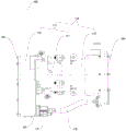
如图1-图8所示,根据本发明实施例的压缩机组件100包括机壳110、压缩部件、和PTC加热器140。As shown in FIGS. 1-8 , a
机壳110包括本体部111和端盖部112,本体部111和端盖部112配合限定出放置腔113,端盖部112上设有与放置腔113间隔设置的盛液腔180,所述压缩部件设在放置腔113内,PTC(Positive Temperature Coefficient,正的温度系数)加热器140设在盛液腔180内以对盛液腔180内的液体进行加热。其中,PTC加热器140具有热阻小、换热效率高等优点。The
举例而言,PTC加热器140包括芯体146和电极板147,芯体146伸入盛液腔180以加热盛液腔180内的液体,芯体146可以通过电极板147与压缩机组件100的控制部分电连接,芯体146可以为金属铝材料制成。盛液腔180可以设有用于拆装PTC加热器140的开口183,压缩机组件100可以包括第一盖板191,第一盖板191可以安装于端盖部112且用于封盖开口183,这样降低了PTC加热器140受损几率,提高了PTC加热器140的安全性,且减少能量的散失。For example, the
本领域技术人员可理解的是,机壳110设有吸气口(图中未示意)和排气口(图中未示意),所述吸气口用于将冷媒吸入至压缩部件内,所述排气口用于将经压缩部件压缩后的冷媒排出。其中,所述吸气口的冷媒温度较低,例如10℃以下,所述排气口的温度较高,例如超过80℃,并且,所述排气口可以靠近盛液腔180。Those skilled in the art can understand that the
根据本发明实施例的压缩机组件100,通过将机壳110设置为包括本体部111和端盖部112,且本体部111和端盖部112配合限定出放置腔113,端盖部112上设有与放置腔113间隔设置的盛液腔180,所述压缩部件设在放置腔113内,在夏天时所述压缩部件做功后可以与盛液腔180中的液体进行热交换以降低所述压缩部件的温度,且由于盛液腔180内的液体不断流动,因此所述压缩部件可以持续与所述液体进行热交换,提高了对所述压缩部件降温的效率,所述压缩部件内部压差可以快速减小,从而降低了停机的几率。According to the
另外,压缩机组件100停机后,由于所述压缩部件内部压差较小,因此压缩机组件100需要较小的功率就可以实现压缩机组件100的启动,这样可以实现压缩机组件100的快速启动。而且由于所述压缩部件内部压差较小,因此压缩机组件100中的功率器件过载风险较低,所述功率器件无需过多余量,这样兼顾了压缩机组件100的使用寿命和生产成本,还可以减小压缩机组件100整体的功耗。In addition, after the
此外,由于PTC加热器140设在盛液腔180内以对盛液腔180内的液体进行加热,因此在冬天时可以在启动所述压缩部件前预先启动PTC加热器140,通过PTC加热器140加热盛液腔180内的液体,所述液体可以将所述压缩部件的温度加热到适宜启动条件,从而实现所述压缩部件在环境温度较低时也可以正常启动。In addition, since the
如此,根据本发明实施例的压缩机组件100能够在高低温工况下实现快速正常启动,且具有成本低、能耗小、使用寿命长等优点。In this way, the
根据本发明的一些具体实施例,如图7所示,PTC加热器140包括第一组肋片141和第二组肋片142,第一组肋片141和第二组肋片142交错设置,第一组肋片141和第二组肋片142可以彼此平行,相邻第一组肋片141和第二组肋片142之间限定出至少一个走液间隙143,第一组肋片141与盛液腔180的内壁之间限定出与走液间隙143连通的第一走液通道144,第二组肋片142与盛液腔180的内壁之间限定出与走液间隙143连通的第二走液通道145。According to some specific embodiments of the present invention, as shown in FIG. 7 , the
具体地,第一走液通道144和第二走液通道145位于PTC加热器140的相对两侧。Specifically, the first
举例而言,第一组肋片141和第二组肋片142可以形成于芯体146且伸入盛液腔180内,第一组肋片141和第二组肋片142设有朝向电极板147凸起的连接片(图中未示意),电极板147设有连接孔,所述连接片和所述连接孔配合,这样既实现第一组肋片141和第二组肋片142分别与电极板147电连接,又固定了芯体146和电极板147之间的相对位置。且PTC加热器140可以通过第一组肋片141和第二组肋片142加热盛液槽内的液体。For example, the first group of
另外,盛液腔180可以包括相对的第一内壁和第二内壁,第一组肋片141可以与所述第一内壁接触且与所述第二内壁间隔形成第一走液通道144,第二组肋片142可以与所述第二内壁接触且与所述第一内壁间隔形成第二走液通道145,第一组肋片141和第二组肋片142沿所述第一内壁的延伸方向(也即所述第二内壁的延伸方向)间隔交错,盛液腔180中的液体在多个走液间隙143、第一走液通道144和第二走液通道145中流动,从而形成S形流路。这样所述液体可以更充分与第一组肋片141、第二组肋片142接触,所述液体与PTC加热器140之间的热交换更充分,进而提高了PTC加热器140对所述液体的加热效率。In addition, the
根据本发明的一些具体实施例,如图2-图4以及图6所示,盛液腔180具有进液口181和出液口182,进液口181和出液口182中的一个与第一走液通道144连通且另一个与第二走液通道145连通。其中,从进液口181进入盛液腔180的液体的温度可以低于60℃。通过设置进液口181和出液口182,便于盛液腔180的液体进出,也可以将所述液体引流到第一走液通道144和第二走液通道145内。According to some specific embodiments of the present invention, as shown in FIG. 2-FIG. 4 and FIG. One
进一步地,盛液腔180内设有多个止抵凸筋(图中未示意),第一组肋片141和第二组肋片142分别止抵在所述止抵凸筋上。其中,所述止挡凸筋构造于盛液腔180的底壁。这样降低了第一组肋片141、第二组肋片142与盛液腔180的底壁之间接触更紧密,保证了所述液体可以更好地沿着多个走液间隙143、第一走液通道144和第二走液通道145的延伸方向流动,避免所述液体未经过第一走液通道144和第二走液通道145而直接在多个走液间隙143之间流动,进而保证所述液体可以更充分与第一组肋片141、第二组肋片142接触,进一步使所述液体与PTC加热器140之间的热交换更充分,进而提高了PTC加热器140对所述液体的加热效率。Further, a plurality of anti-resistance ribs (not shown in the figure) are provided in the
根据本发明的一些具体实施例,如图2和图6所示,出液口182位于盛液腔180的顶部,这样可以避免盛液腔180的顶部发生气泡集中,防止发生PTC加热器140干烧的情况。另外,进液口181可以位于盛液腔180的底部,由于进液口181的液体的温度低于出液口182的液体的温度,因此可以提高所述压缩部件的散热几率。According to some specific embodiments of the present invention, as shown in Fig. 2 and Fig. 6, the
根据本发明的一些具体实施例,如图3和图4所示,机壳110上还设有电控腔室150,电控腔室150内设有电控装置151,电控装置151分别与所述压缩部件和PTC加热器140电连接以控制所述压缩部件和PTC加热器140的运行状态。According to some specific embodiments of the present invention, as shown in Fig. 3 and Fig. 4, an
举例而言,机壳110可以包括用于遮盖电控腔室150的第二盖板192,第二盖板192和机壳110可以通过螺纹紧固件(例如,螺栓)连接。电控腔室150可以靠近所述压缩部件的吸气口,由于电控装置151中可以设有多种电气元件(例如,功率元件),因此电控装置151运行时会产生较高的温度,利用所述吸气口的低温冷媒可以为电控装置151降温。通过电控装置151可以更好地控制所述压缩部件和PTC加热器140的运行。For example, the
进一步地,如图5所示,电控装置151包括电控板152、第一IGBT模块153和第二IGBT模块154。电控板152设在电控腔室150内,第一IGBT模块153分别与电控板152和所述压缩部件电连接,第二IGBT模块154分别与电控板152和PTC加热器140电连接。其中,第一IGBT模块153和所述所述压缩部件可以通过电阻焊的方式焊接,并且电控板152可以通过高压插接件172与外界高压电源相连,这样电控装置151可以为压缩机组件100中的高压元件(例如,PTC加热器140)供电,电控板152可以通过低压插接件173和外界通讯,且为压缩机组件100中的低压元件供电。通过电控板152可以同时控制所述压缩部件和PTC加热器140,无需为所述压缩部件和PTC加热器140各自单独设置电控板,提高了空间利用率,减轻了压缩机组件100的重量,也降低了压缩机组件100的耗能。Further, as shown in FIG. 5 , the
根据本发明的一些具体实施例,如图3-图5所示,压缩机组件100还包括弹性件161,弹性件161固定在机壳110上且止抵在电控装置151上以将电控装置151定位在电控腔室150内。其中,弹性件161可以为刚性弹片。According to some specific embodiments of the present invention, as shown in FIGS. 3-5 , the
举例而言,弹性件161的一部分可以和电控装置151层叠,换言之,电控装置151可以位于弹性件161和机壳110之间,弹性件161的其余部分通过螺纹紧固件(例如,螺栓)安装于机壳110。通过弹性件161定位电控装置151和机壳110之间的相对位置,由于弹性件161具有弹性形变的能力,因此电控装置151可以尺寸不相同,弹性件161可以随着电控装置151的形状而形变,压缩机组件100可以根据实际使用需求选择不同的电控装置151,提高了压缩机组件100的普适性。并且,弹性件161形变后的弹性恢复力会使电控装置151与机壳110之间贴合更紧密,压缩机组件100整体的结构更加稳定。For example, a part of the
根据本发明的一些具体实施例,电控装置151和机壳110之间设有绝缘件(图中未示意)。所述绝缘件可以为绝缘陶瓷片或者绝缘垫片。通过绝缘件的设置,可以保证电控装置151和机壳110绝缘,即电控装置151和机壳110之间不存在电导通,保证了电控装置151的可靠性,防止电控装置151发生短路等情况。According to some specific embodiments of the present invention, an insulating member (not shown in the figure) is provided between the
进一步地,如图3和图5所示,所述绝缘件与机壳110之间设有导热件163。导热件163可以为导热硅脂,导热硅脂涂抹到机壳110,所述绝缘件贴合到涂抹过导热硅脂的机壳110,电控装置151再安装到所述绝缘件的背向机壳110的一侧。由于电控装置151设有功率元件(例如,第一IGBT模块153和第二IGBT模块154),并且由于功率元件工作时的热量较高,因此通过设置导热件163可以增加电控装置151的整体散热效率,保证电控装置151的工作效率和使用寿命。并且,在本发明的一些实施中,电控装置151也可以设有导热件163,例如将导热硅脂涂抹到第一IGBT模块153和第二IGBT模块154的表面,进一步地提高电控装置151整体的散热效率。Further, as shown in FIG. 3 and FIG. 5 , a
根据本发明的一些具体实施例,如图1-图3所示,机壳110上设有与电控装置151电连接的第一插接头115,压缩机组件100还包括连接线束170,连接线束170的一端与PTC加热器140电连接,连接线束170的另一端设有第二插接头171,第二插接头171与第一插接头115插接配合以使PTC加热器140与电控装置151电连接。如此,电控装置151可以为PTC加热器140供电,PTC加热器140产生热量以加热盛液腔180内的液体,且电连接可靠,插拔方便。According to some specific embodiments of the present invention, as shown in FIGS. 1-3 , the
根据本发明的一些具体实施例,如图1所示,本体部111包括第一腔壳116和第二腔壳117,第一腔壳116固定在第二腔壳117上,第一腔壳116内限定出电控腔室150,第二腔壳117和端盖部112配合限定出放置腔113。According to some specific embodiments of the present invention, as shown in FIG. An
举例而言,第一腔壳116和第二腔壳117可以通过螺纹紧固件(例如,螺栓)连接,第二腔壳117位于第一腔壳116和端盖部112之间。第一IGBT模块153和第二IGBT模块154可以放置在第一腔壳116的壳底,所述压缩部件可以通过螺纹紧固件安装于第二腔壳117。For example, the
这样通过将本体部111分为第一腔壳116和第二腔壳117,便于本体部111的生产加工,也便于对电控装置151和所述压缩部件的维修和更换,提高了压缩机组件100的使用寿命和安全性。In this way, by dividing the
根据本发明的一些具体实施例,如图4所示,所述压缩部件包括压缩静盘121、压缩动盘和电机,所述电机与所述压缩动盘配合以驱动压缩动盘转动,压缩静盘121和所述压缩动盘配合以压缩冷媒。其中,电控装置151可以通过三相连接柱122与所述电机的三项插头连接,三相连接柱122可以通过波峰焊的焊接方式与电控装置151连接。According to some specific embodiments of the present invention, as shown in FIG. 4 , the compression component includes a compression
具体地,压缩静盘121和所述压缩动盘配合可以将低温低压气态冷媒压缩为高温高压气态冷媒,形成了冷媒的物理状态的转换,并且可以驱动了冷媒流动。这样所述压缩部件可以对冷媒进行压缩和驱动,便于具有压缩机组件100的空调可以实现正常的功能,例如制冷功能或者制热功能。Specifically, the combination of the
下面参考附图描述根据本发明实施例的车辆,所述车辆包括车体和根据本发明上述实施例压缩机组件100,压缩机组件100固定在所述车体上。A vehicle according to an embodiment of the present invention will be described below with reference to the accompanying drawings. The vehicle includes a vehicle body and a
举例而言,所述车辆可以设有水泵,所述水泵可以将盛液腔180内的液体送至所述车辆的其余位置。相关技术中车辆的压缩部件和PTC加热器140分别独立设置,本发明的车辆中将压缩部件与PTC加热器140集成为一体,即实现所述车辆的空调系统和加热系统集成为一体,所述压缩部件和PTC加热器140可以共用安装支架,提高了空间利用率,减小了安装工时,减轻整车重量,提高所述车辆的行驶里程。For example, the vehicle may be provided with a water pump, and the water pump may send the liquid in the
根据本发明实施例的车辆,通过利用根据本发明上述实施例的压缩机组件100,保证空调快速正常启动。According to the vehicle of the embodiment of the present invention, by using the
根据本发明实施例的压缩机组件100和所述车辆的其他构成以及操作对于本领域普通技术人员而言都是已知的,这里不再详细描述。Other configurations and operations of the
在本说明书的描述中,参考术语“具体实施例”、“具体示例”等的描述意指结合该实施例或示例描述的具体特征、结构、材料或者特点包含于本发明的至少一个实施例或示例中。在本说明书中,对上述术语的示意性表述不一定指的是相同的实施例或示例。In the description of this specification, descriptions with reference to the terms "specific embodiment", "specific example" and the like mean that specific features, structures, materials or characteristics described in conjunction with the embodiment or example are included in at least one embodiment or embodiment of the present invention. example. In this specification, schematic representations of the above terms do not necessarily refer to the same embodiment or example.
尽管已经示出和描述了本发明的实施例,本领域的普通技术人员可以理解:在不脱离本发明的原理和宗旨的情况下可以对这些实施例进行多种变化、修改、替换和变型,本发明的范围由权利要求及其等同物限定。Although the embodiments of the present invention have been shown and described, those skilled in the art can understand that various changes, modifications, substitutions and modifications can be made to these embodiments without departing from the principle and spirit of the present invention. The scope of the invention is defined by the claims and their equivalents.
Claims (14)
Priority Applications (1)
| Application Number | Priority Date | Filing Date | Title |
|---|---|---|---|
| CN202010865185.8A CN114087163B (en) | 2020-08-25 | 2020-08-25 | Compressor assembly and vehicle with same |
Applications Claiming Priority (1)
| Application Number | Priority Date | Filing Date | Title |
|---|---|---|---|
| CN202010865185.8A CN114087163B (en) | 2020-08-25 | 2020-08-25 | Compressor assembly and vehicle with same |
Publications (2)
| Publication Number | Publication Date |
|---|---|
| CN114087163A CN114087163A (en) | 2022-02-25 |
| CN114087163B true CN114087163B (en) | 2023-03-14 |
Family
ID=80295001
Family Applications (1)
| Application Number | Title | Priority Date | Filing Date |
|---|---|---|---|
| CN202010865185.8A Active CN114087163B (en) | 2020-08-25 | 2020-08-25 | Compressor assembly and vehicle with same |
Country Status (1)
| Country | Link |
|---|---|
| CN (1) | CN114087163B (en) |
Families Citing this family (2)
| Publication number | Priority date | Publication date | Assignee | Title |
|---|---|---|---|---|
| CN116803709A (en) * | 2023-04-21 | 2023-09-26 | 浙江三花智能控制股份有限公司 | Integrated device |
| CN118361379A (en) * | 2024-05-15 | 2024-07-19 | 苏州中成新能源科技股份有限公司 | An electric compressor with integrated heating module |
Family Cites Families (5)
| Publication number | Priority date | Publication date | Assignee | Title |
|---|---|---|---|---|
| WO2014000666A1 (en) * | 2012-06-27 | 2014-01-03 | Shenzhen Byd Auto R&D Company Limited | Ptc electric heating assembly, electric heating device and electric vehicle |
| CN103517469B (en) * | 2012-06-27 | 2015-03-04 | 比亚迪股份有限公司 | PTC electrical heating element, electric heater unit and electric car |
| CN203687327U (en) * | 2013-12-13 | 2014-07-02 | 比亚迪股份有限公司 | Ptc liquid heating device |
| CN111251809B (en) * | 2018-11-30 | 2022-07-19 | 比亚迪股份有限公司 | Thermal management system of vehicle and vehicle |
| CN110080985A (en) * | 2019-05-20 | 2019-08-02 | 湖南贝特新能源科技有限公司 | A kind of heating device of screw compressor |
-
2020
- 2020-08-25 CN CN202010865185.8A patent/CN114087163B/en active Active
Also Published As
| Publication number | Publication date |
|---|---|
| CN114087163A (en) | 2022-02-25 |
Similar Documents
| Publication | Publication Date | Title |
|---|---|---|
| CN103517469B (en) | PTC electrical heating element, electric heater unit and electric car | |
| CN102686881B (en) | Inverter-integrated electric compressor | |
| CN114087163B (en) | Compressor assembly and vehicle with same | |
| WO2004025807A1 (en) | Drive device | |
| CN103517467B (en) | A kind of PTC electric heating element, electric heater unit and electric motor car | |
| CN116292297B (en) | Electric compressor and vehicle | |
| CN103634952B (en) | A kind of PTC electric heating element, electric heater unit and electric motor car | |
| CN106870370A (en) | Compressor and the vehicle with it | |
| CN219412911U (en) | Electric compressor and vehicle | |
| CN204239197U (en) | Compressor | |
| CN202713643U (en) | PTC electrical heating element, electrical heating device, and electrombile | |
| JP4436192B2 (en) | Control device for electric compressor | |
| JP2008180120A (en) | Electric compressor | |
| CN217241209U (en) | Self-adjusting motor controller of electric vehicle | |
| CN213205977U (en) | Compressor assembly and vehicle having the same | |
| CN215170671U (en) | Controller subassembly and compressor | |
| CN215345104U (en) | Electric vehicle, electric heater, and electrode mounting structure | |
| CN117641702A (en) | Vehicle and thermal management integrated device thereof | |
| JP2008163764A (en) | Electric compressor | |
| JP4830848B2 (en) | Electric compressor | |
| JP2008163765A (en) | Electric compressor | |
| JP2008163767A (en) | Electric compressor | |
| JP2008175068A (en) | Electric compressor | |
| CN219412910U (en) | Electric compressor and vehicle | |
| CN223825238U (en) | A self-heating compressor and thermal management system |
Legal Events
| Date | Code | Title | Description |
|---|---|---|---|
| PB01 | Publication | ||
| PB01 | Publication | ||
| SE01 | Entry into force of request for substantive examination | ||
| SE01 | Entry into force of request for substantive examination | ||
| GR01 | Patent grant | ||
| GR01 | Patent grant |