Disclosure of Invention
In order to solve the problem of uneven viewpoint distribution in the existing three-dimensional light field display technology, the invention provides a three-dimensional light field display system for uniformly distributing viewpoints so as to achieve the technical purposes of improving the viewpoint distribution uniformity, meeting the requirement of watching by multiple people and the like.
In order to achieve the technical purpose, the invention provides a three-dimensional light field display system for uniformly distributing viewpoints, which can include, but is not limited to, a collimating backlight device, a liquid crystal display screen, an aspheric cylindrical lens grating and a holographic function screen which are arranged in sequence along a light path.
And the collimation backlight device is used for emitting directional light rays.
And the liquid crystal display screen is used for modulating the directional light for the first time to obtain modulated light.
And the aspheric cylindrical lens grating is used for performing refraction adjustment on the modulated light and generating emergent light which is uniformly distributed.
And the holographic function screen is used for carrying out secondary modulation on the uniformly distributed emergent rays and forming a three-dimensional display visual area.
Further, the aspheric cylindrical lens grating comprises a plurality of aspheric cylindrical lenses arranged in parallel.
An aspheric cylindrical lens having a first convex surface and a second convex surface; the first convex surface faces the liquid crystal display screen, and the second convex surface faces the holographic function screen.
Furthermore, the first convex surface is used for carrying out primary refraction adjustment on the modulated light rays and enabling projection distances of the light rays after primary refraction adjustment to be the same on the reference plane corresponding to the second convex surface.
And the second convex surface is used for carrying out secondary refraction adjustment on the light after the primary refraction adjustment and generating emergent light which is uniformly distributed.
Further, the first convex surface comprises a first cambered surface and a second cambered surface which are symmetrically arranged; the first cambered surface and the second cambered surface are the same in structure. The second convex surface comprises a third cambered surface and a fourth cambered surface which are symmetrically arranged; the third cambered surface is the same as the fourth cambered surface in structure.
Further, a maximum distance between the first convex surface and the second convex surface is a maximum distance between the first common line and the second common line; the first common line is a common line of the first cambered surface and the second cambered surface, and the second common line is a common line of the third cambered surface and the fourth cambered surface.
Further, the first convex surface and the second convex surface have different radii of curvature.
Further, the first convex surface and the second convex surface have different conic coefficients.
Further, the system further comprises: and the optical deflection film is arranged between the aspheric cylindrical lens grating and the holographic functional screen along the light path and is used for deflecting the uniformly distributed emergent light rays.
Further, the collimation backlight device comprises a light source and a Fresnel lens which are arranged in sequence.
And the light source is used for emitting scattered light.
The Fresnel lens is used for refracting the scattered light to form directional light.
Further, the light source is a light emitting diode light source.
The invention has the beneficial effects that: the invention effectively changes the emergent position of light on the cylindrical lens based on the aspheric cylindrical lens grating, thereby generating emergent light with uniform distribution, and further achieving the purpose of constructing uniformly distributed viewpoints, namely, the viewpoint distribution densities of the middle position of the watching area and the positions at the edge of the watching area are almost the same, and viewers at different positions can see parallax images with almost the same number, thereby obtaining the same three-dimensional effect, and further meeting the requirement of watching by multiple people at the same time. Moreover, the invention provides uniformly distributed viewpoints to ensure that a viewer can obtain very uniform and smooth motion parallax when moving, and the user experience is excellent.
Detailed Description
The following explains and explains a three-dimensional light field display system for uniform viewpoint distribution according to the present invention in detail with reference to the drawings.
The invention provides a three-dimensional light field display system for uniformly distributing viewpoints, which aims to solve the problems of nonuniform viewpoint distribution, different numbers of parallax images seen by observers at different positions, unsmooth motion parallax transition of images obtained by the observers during motion and the like in the traditional three-dimensional light field display technology. It should be understood that the viewpoint in the present invention refers to a convergence position formed by converging light rays emitted by different voxels in space, where a correct parallax image can be viewed, and is called a viewpoint, for example, the uppermost convergence point in fig. 1. The parallax image according to the present invention is two or more images having parallax obtained by photographing the same scene from different angles by simulating stereoscopic vision of human eyes, and is referred to as a parallax image. The volume pixel refers to a light-emitting object point on a three-dimensional object represented in three-dimensional light field display, and light rays emitted by the volume pixel to different directions have different information such as color, intensity and the like.
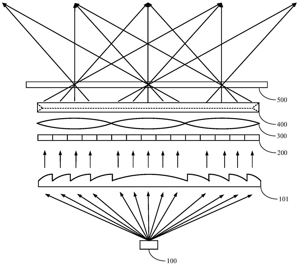
As shown in fig. 1 and 2, the embodiment of the present invention can specifically provide a three-dimensional light field display system for viewpoint uniform distribution, where the light field display system may include, but is not limited to, a collimating backlight device, a liquid crystal display 200, an aspheric cylindrical lenticular lens 300, and a holographic functional screen 500, which are sequentially disposed along a light path.
A collimated backlight may be used to emit directional light. Specifically, the collimating backlight device in the embodiment of the present invention includes a light source 100 and a fresnel lens 101 that are sequentially disposed. The light source 100 can be used to emit scattered light, and the fresnel lens 101 can be used to refract the scattered light to form directional light. In the embodiment of the present invention, the scattered light is refracted when passing through the fresnel lens 101, and becomes a directional light in the vertical direction. The Light source 100 in the present embodiment is specifically a Light-Emitting Diode (LED) Light source. The light source 100 is specifically disposed at the focal point of the fresnel lens 101 to illuminate the entire fresnel lens 101.
The liquid crystal display screen 200 may be configured to modulate the directional light irradiated thereon for the first time to obtain modulated light; the lcd panel 200 is an lcd (liquid Crystal display) panel. In the embodiment of the present invention in which the directional light in the vertical direction passes through the liquid crystal display panel 200, since the encoded composite image is displayed on the liquid crystal display panel 200, the light, when passing through the liquid crystal display panel 200, carries the color and intensity information of the corresponding pixels in the display panel for reproducing the three-dimensional image in space. The synthesized image in the invention means that corresponding pixels on the parallax image are coded and mapped onto an image and displayed on a liquid crystal display screen by using a certain coding and mapping rule, and the image is called as the synthesized image.
The aspheric cylindrical lens grating 300 is used for performing refraction adjustment on the modulated light and generating emergent light with uniform distribution. The modulated light carrying the color and intensity information of the corresponding pixels in the display screen is refracted when encountering the aspheric cylindrical lenticular lens 300.
Specifically, the aspherical cylindrical lens grating 300 includes a plurality of aspherical cylindrical lenses arranged in parallel, and the aspherical cylindrical lenses may have a first convex surface 310 and a second convex surface 320, i.e., two sides of the aspherical cylindrical lenses, e.g., an anterior side and a posterior side; the first convex surface 310 faces the liquid crystal display panel 200, and the second convex surface 320 faces the hologram functional panel 500. The first convex surface 310 may be used to perform a first refraction adjustment on the modulated light, and make the projection distances of the first refraction-adjusted light on the reference plane corresponding to the second convex surface 320 the same. The second convex surface 320 of the present invention is used for performing a second refraction adjustment on the light after the first refraction adjustment, and generating an outgoing light with uniform distribution.
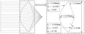
As shown in fig. 3, and may be combined with fig. 4 to further illustrate the structure of the aspheric cylindrical lens in the present invention, in the embodiment of the present invention, the first convex surface 310 includes a first arc surface 311 and a second arc surface 312, which are symmetrically disposed, and the symmetry plane may be a plane (as shown by a dotted line in fig. 3) passing through the center of the cylindrical lens; the first cambered surface 311 and the second cambered surface 312 have the same structure; the second convex surface 320 includes a third arc surface 321 and a fourth arc surface 322 which are symmetrically arranged, and the symmetric plane may be a plane passing through the center of the cylindrical lens (as shown by a dotted line in fig. 3); the third arc 321 is identical to the fourth arc 322. The maximum distance between the first convex 310 and the second convex 320 is the maximum distance between the first common line and the second common line; the first common line is a common line of the first arc surface 311 and the second arc surface 312, and the second common line is a common line of the third arc surface 321 and the fourth arc surface 322. The first convex surface 310 and the second convex surface 320 have different radii of curvature. The first convex surface 310 is different from the second convex surface 320 in conical coefficient, and the invention in the following text exemplifies specific curvature radius and conical coefficient.
As shown in FIG. 5, the incident light is parallel to the principal optical axis of the cylindrical lens and is uniformly distributed, and the adjacent light has the same interval Δ d1The light rays are refracted on the front surface and the rear surface of the cylindrical lens and finally exit and converge to the focus. In order to make the emergent light rays uniformly distributed and converged into one point, the invention optimizes the cylindrical lens structure, reduces aberration and simultaneously makes the distance delta d of the light rays in the horizontal direction more critical2Equal, i.e. the projection distance Δ d of the first refraction adjusted light ray on the reference plane corresponding to the second convex surface 3202The same is true.
θn=θ/2
di=|i|*Δd2=ftanθi
Wherein f denotes a focal length of the cylindrical lens, diRepresents a light ray riA distance between an exit position on the cylindrical lens and a principal optical axis of the cylindrical lens; theta denotes the viewing angle, i.e. the maximum angle between the emergent rays at the edge of the cylindrical lens in the embodiment of the present invention, r0、r1、r-1、……、rn、r-nRepresenting a total of 2n +1 rays, theta0、θ1、θ-1、……、θn、θ-nRepresenting the angle between each outgoing ray and the principal optical axis of the lens.
The limiting condition for determining the optimized cylindrical lens parameters is thetaiThe present invention describes the front and back surfaces of a cylindrical lens to be optimized by the following expressions of even-order aspherical surfaces, respectively.
Where c is 1/r, r is the curvature of the aspherical reference surface, k is the conic coefficient of the aspherical surface, and α 2, α 4, and α 6 … … are the high-order coefficients of the aspherical surface.
It should be understood that in the optimization process, the curvature radius of the aspheric surface, the cone coefficient and the distance between the front surface and the rear surface can be set as variables, the damping least square method is adopted to optimize the aberration and the emergent ray angle, and the optimal result is calculated after multiple iterations.
As shown in fig. 4, the embodiment of the present invention provides specific parameter information of an optimized aspheric cylindrical lens structure.
Wherein, for the front surface of the aspheric cylindrical lens, i.e. the first cambered surface 311, the curvature radius r of the first cambered surface 31110.198mm, cone coefficient k1Is-10.095, a high order coefficient alpha15.091; for the rear surface of the aspheric cylindrical lens, i.e. the second arc surface 312, and the curvature radius r of the second arc surface 3122Is-0.043 mm, cone coefficient k2Is-5.023, a high order coefficient alpha2Is 0.733; the aspherical cylindrical lens has a refractive index n of 1.5168, a maximum thickness of 0.072mm in the direction of the main optical axis, and a maximum height of 0.16 mm.
And the holographic function screen 500 is used for carrying out secondary modulation on the uniformly distributed emergent rays and forming a three-dimensional display visual area. The refracted uniformly distributed emergent rays of the present invention converge at the focus on the hologram functional screen 500. Specifically, the holographic functional screen 500 in the embodiment of the present invention is an oriented diffusion film, and the oriented diffusion film is used for modulating the outgoing light, so that the outgoing light is diffused at a certain angle in space.
The three-dimensional light field display system for viewpoint uniform distribution in the embodiment of the present invention may further include an optical deflection film 400. The optical deflection film 400 is disposed between the aspherical cylindrical lens grating 300 and the holographic functional screen 500 along a light path, and is used for deflecting the uniformly distributed emergent light. That is, in this embodiment, the direction of the emergent light is adjusted before the refracted emergent light with uniform distribution is converged, so as to be suitable for users to watch; the present embodiment deflects the direction of the emergent light to the right front.
The present invention constructs a voxel based on the converged emergent light rays on the holographic functional screen 500, and the voxel can emit light rays carrying different viewpoint information (including but not limited to color information and intensity information) to different directions, thereby characterizing the light-emitting object on the three-dimensional object. For the same voxel, the viewer can receive light rays with different viewpoint information at different viewing positions, and the light rays emitted by all the voxels jointly reconstruct the light field distribution of the three-dimensional object, thereby reproducing real and natural 3D images and forming a stereoscopic impression.
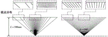
As shown in fig. 6, comparing the spatial distribution of viewpoints before and after optimization with an example of a viewing angle of 100 ° and a viewing distance of 500mm, it can be seen that the three-dimensional light field display system based on the aspheric cylindrical lens provided by the present invention has a more uniform viewpoint distribution. The three-dimensional light field display system provided by the invention has approximately equal distance between adjacent viewpoints at any position in the viewing area, so that a viewer can obtain 3D images with equal quality at any position in the viewing area, and the aim of smooth motion parallax transition is fulfilled.
In summary, the present invention effectively changes the exit position of light on the cylindrical lens based on the aspheric cylindrical lens grating obtained by optimization, and the embodiment of the present invention generates uniformly distributed exit light, so that the exit light approximately converges at the focus, thereby achieving the purpose of constructing uniformly distributed viewpoints, that is, the viewpoint distribution densities at the middle position of the viewing area and at the edge of the viewing area are almost the same, so as to avoid the problems of small and dense viewpoint distances at the middle position of the viewing area, but large and sparse viewpoint distances at positions near the edge of the viewing area, and viewers at different positions will see parallax images with almost the same number, thereby obtaining the same stereoscopic effect, and further satisfying the requirement of simultaneous viewing by multiple persons. Moreover, the invention provides uniformly distributed viewpoints to ensure that the viewer can obtain very uniform and smooth motion parallax even when moving, and the user experience is excellent.
In addition, the three-dimensional light field display system for uniformly distributing the viewpoints can be used in scenes such as an electronic sand table, and therefore high-quality three-dimensional geographic terrain images with uniformly distributed viewpoints are provided for users.
In the description herein, references to the description of the term "the present embodiment," "one embodiment," "some embodiments," "an example," "a specific example," or "some examples," etc., mean that a particular feature, structure, material, or characteristic described in connection with the embodiment or example is included in at least one embodiment or example of the present invention. In this specification, the schematic representations of the terms used above are not necessarily intended to refer to the same embodiment or example. Furthermore, the particular features, structures, materials, or characteristics described may be combined in any suitable manner in any one or more embodiments or examples. Furthermore, various embodiments or examples and features of different embodiments or examples described in this specification can be combined and combined by one skilled in the art without contradiction.
Furthermore, the terms "first", "second" and "first" are used for descriptive purposes only and are not to be construed as indicating or implying relative importance or implicitly indicating the number of technical features indicated. Thus, a feature defined as "first" or "second" may explicitly or implicitly include at least one such feature. In the description of the present invention, "a plurality" means at least two, e.g., two, three, etc., unless specifically limited otherwise.
In the description of the present invention, it is to be understood that the terms "central," "longitudinal," "lateral," "length," "width," "thickness," "upper," "lower," "front," "rear," "left," "right," "vertical," "horizontal," "top," "bottom," "inner," "outer," "clockwise," "counterclockwise," "axial," "radial," "circumferential," and the like are used in the orientations and positional relationships indicated in the drawings for convenience in describing the invention and to simplify the description, and are not intended to indicate or imply that the referenced devices or elements must have a particular orientation, be constructed and operated in a particular orientation, and are therefore not to be considered limiting of the invention.
In the present invention, unless otherwise expressly stated or limited, the terms "mounted," "connected," "secured," and the like are to be construed broadly and can, for example, be fixedly connected, detachably connected, or integrally formed; can be mechanically or electrically connected; they may be directly connected or indirectly connected through intervening media, or they may be connected internally or in any other suitable relationship, unless expressly stated otherwise. The specific meanings of the above terms in the present invention can be understood by those skilled in the art according to specific situations.
The above description is only for the purpose of illustrating the preferred embodiments of the present invention and is not to be construed as limiting the invention, and any modifications, equivalents and simplifications made in the spirit of the present invention are intended to be included in the scope of the present invention.