CN113940605A - Endoscope with a detachable handle - Google Patents
Endoscope with a detachable handle Download PDFInfo
- Publication number
- CN113940605A CN113940605A CN202111069703.6A CN202111069703A CN113940605A CN 113940605 A CN113940605 A CN 113940605A CN 202111069703 A CN202111069703 A CN 202111069703A CN 113940605 A CN113940605 A CN 113940605A
- Authority
- CN
- China
- Prior art keywords
- module
- endoscope
- liquid lens
- optical signal
- focusing
- Prior art date
- Legal status (The legal status is an assumption and is not a legal conclusion. Google has not performed a legal analysis and makes no representation as to the accuracy of the status listed.)
- Pending
Links
Images


Classifications
-
- A—HUMAN NECESSITIES
- A61—MEDICAL OR VETERINARY SCIENCE; HYGIENE
- A61B—DIAGNOSIS; SURGERY; IDENTIFICATION
- A61B1/00—Instruments for performing medical examinations of the interior of cavities or tubes of the body by visual or photographical inspection, e.g. endoscopes; Illuminating arrangements therefor
- A61B1/00002—Operational features of endoscopes
- A61B1/00004—Operational features of endoscopes characterised by electronic signal processing
- A61B1/00009—Operational features of endoscopes characterised by electronic signal processing of image signals during a use of endoscope
-
- A—HUMAN NECESSITIES
- A61—MEDICAL OR VETERINARY SCIENCE; HYGIENE
- A61B—DIAGNOSIS; SURGERY; IDENTIFICATION
- A61B1/00—Instruments for performing medical examinations of the interior of cavities or tubes of the body by visual or photographical inspection, e.g. endoscopes; Illuminating arrangements therefor
- A61B1/04—Instruments for performing medical examinations of the interior of cavities or tubes of the body by visual or photographical inspection, e.g. endoscopes; Illuminating arrangements therefor combined with photographic or television appliances
- A61B1/05—Instruments for performing medical examinations of the interior of cavities or tubes of the body by visual or photographical inspection, e.g. endoscopes; Illuminating arrangements therefor combined with photographic or television appliances characterised by the image sensor, e.g. camera, being in the distal end portion
Landscapes
- Health & Medical Sciences (AREA)
- Life Sciences & Earth Sciences (AREA)
- Surgery (AREA)
- Engineering & Computer Science (AREA)
- Biomedical Technology (AREA)
- Molecular Biology (AREA)
- Pathology (AREA)
- Radiology & Medical Imaging (AREA)
- Nuclear Medicine, Radiotherapy & Molecular Imaging (AREA)
- Biophysics (AREA)
- Physics & Mathematics (AREA)
- Heart & Thoracic Surgery (AREA)
- Medical Informatics (AREA)
- Optics & Photonics (AREA)
- Animal Behavior & Ethology (AREA)
- General Health & Medical Sciences (AREA)
- Public Health (AREA)
- Veterinary Medicine (AREA)
- Signal Processing (AREA)
- Endoscopes (AREA)
- Instruments For Viewing The Inside Of Hollow Bodies (AREA)
Abstract
The application provides an endoscope, and relates to the technical field of optical imaging. The endoscope includes: the optical signal transmission assembly is used for transmitting an optical signal to the objective lens assembly; the driver is used for driving the optical signal transmission assembly to scan; and the objective lens assembly is used for adjusting the focusing of the optical signal to different depth positions corresponding to the sample to be shot, wherein the objective lens assembly comprises a liquid lens structure. This application introduces endoscope system with liquid lens, and liquid lens zooms and compares traditional machinery structure that zooms, and it is fast not only to possess response speed, can zoom at a high speed in a flexible way, and control advantage such as simple can be convenient for the endoscope probe integrate, can satisfy two-photon endoscope to three-dimensional tissue imaging demand, be favorable to further obtaining three-dimensional imaging information to the screening and the diagnosis of auxiliary disease.
Description
Technical Field
The application relates to the technical field of optical imaging, in particular to an endoscope.
Background
The multi-photon endoscope has the tomography capability, and can perform high-resolution imaging on an X-Y plane sample to obtain two-dimensional plane information of a sample tissue. However, since the multiphoton endoscope does not have an axial focusing device, there is a problem that depth Z-direction scanning cannot be performed on a sample to be scanned, so that three-dimensional imaging information of the sample to be scanned cannot be obtained.
Disclosure of Invention
The present application is proposed to solve the above-mentioned technical problems. The embodiment of the application provides an endoscope.
An embodiment of the present application provides an endoscope comprising: the optical signal transmission assembly is used for transmitting an optical signal to the objective lens assembly; the driver is used for driving the optical signal transmission assembly to scan; and the objective lens assembly is used for adjusting the focusing of the optical signal to different depth positions corresponding to the sample to be shot.
In some implementations of the first aspect, the objective lens assembly includes a collimation and beam expansion module, a focusing module, and a convergence module, which are sequentially arranged, where the collimation and beam expansion module is configured to collimate and expand an optical signal emitted by the optical signal transmission assembly; the focusing module is used for adjusting the direction of the optical signal emitted by the collimation and beam expansion module; the convergence module is used for focusing the optical signals emitted by the focusing module to different depth positions corresponding to the sample to be shot.
In certain implementations of the first aspect, the focusing module includes a liquid lens, and the focusing module adjusts a direction of an optical signal emitted by the collimated beam expanding module according to a working state of the liquid lens, where the working state of the liquid lens includes a concave lens state, a flat plate state, and a convex lens state.
In certain implementations of the first aspect, the focusing module is further configured to: if the liquid lens is in a concave lens state, the focusing module emits a divergent light signal; if the liquid lens is in a flat plate state, the focusing module emits parallel light signals; if the liquid lens is in a convex lens state, the focusing module emits a convergent light signal.
In certain implementations of the first aspect, the aggregation module is further configured to: if the focusing module emits the divergent light signal, the convergence module focuses the divergent light signal to a first depth position corresponding to a sample to be shot; if the focusing module emits the parallel optical signal, the converging module focuses the parallel optical signal to a second depth position corresponding to the sample to be shot; and if the focusing module emits the converged light signal, the converged light signal is focused to a third depth position corresponding to the sample to be shot by the converging module.
In certain implementations of the first aspect, the scan range of the endoscope is determined based on an imaging depth corresponding to the first depth position and an imaging depth corresponding to the third depth position.
In certain implementations of the first aspect, the endoscope includes a voltage control module coupled to the liquid lens for adjusting a voltage applied to the liquid lens to adjust a working state of the liquid lens.
In certain implementations of the first aspect, the endoscope includes a pressure adjustment module coupled to the liquid lens for adjusting a pressure applied to the liquid lens to adjust an operating state of the liquid lens.
In certain implementations of the first aspect, the focusing module is located between the collimated beam expanding module and the converging module.
In certain implementations of the first aspect, the collimated beam expanding module includes any one or a combination of plano-convex, biconvex, plano-concave, and biconcave lenses.
The embodiment of the application provides an endoscope, which drives an optical signal transmission assembly to scan through a driver; the optical signal transmission component transmits an optical signal to the objective lens component; the objective lens assembly enables the optical signals in different directions to be focused to different depth positions corresponding to the sample to be shot by adjusting the direction of the optical signals. The method and the device can meet the requirement of the endoscope on three-dimensional imaging of the sample to be shot, and are favorable for acquiring the three-dimensional imaging information of the sample to be shot, so that screening and diagnosis of diseases are assisted.
Drawings
The above and other objects, features and advantages of the present application will become more apparent by describing in more detail embodiments of the present application with reference to the attached drawings. The accompanying drawings are included to provide a further understanding of the embodiments of the application and are incorporated in and constitute a part of this specification, illustrate embodiments of the application and together with the description serve to explain the principles of the application. In the drawings, like reference numbers generally represent like parts or steps.
Fig. 1 is a schematic structural diagram of an endoscope provided in an exemplary embodiment of the present application.
Fig. 2 is a schematic structural diagram of a liquid lens according to an exemplary embodiment of the present application.
Fig. 3 is a schematic structural diagram of an endoscope provided in another exemplary embodiment of the present application.
Fig. 4 is a schematic flow chart illustrating a process of adjusting a liquid lens by a voltage control module according to an exemplary embodiment of the present application.
Fig. 5 is a schematic structural diagram of an endoscope provided in another exemplary embodiment of the present application.
Detailed Description
The technical solutions in the embodiments of the present application will be clearly and completely described below with reference to the drawings in the embodiments of the present application, and it is obvious that the described embodiments are only a part of the embodiments of the present application, and not all of the embodiments. All other embodiments, which can be derived by a person skilled in the art from the embodiments given herein without making any creative effort, shall fall within the protection scope of the present application.
Fig. 1 is a schematic structural diagram of an endoscope provided in an exemplary embodiment of the present application. As shown in fig. 1, the endoscope includes an optical signal transmission assembly S1, a driver S2, and an objective lens assembly S3. The optical signal transmission assembly S1 is used for transmitting an optical signal to the objective lens assembly S3. The driver S2 is used to drive the optical signal transmission module S1 to scan. The objective lens assembly S3 is used for adjusting the focusing of the light signal to different depth positions corresponding to the sample S4 to be shot.
Specifically, there is a connection relationship between the driver S2 and the optical signal transmission module S1, one end of the optical signal transmission module S1 is fixed on the driver S2, the driver S2 excites the optical signal transmission module S1 to vibrate, and the other end of the optical signal transmission module S1 is a free end, and the free end is used for completing scanning by vibration. The driver S2 is used to drive the optical signal transmission module S1 to perform periodic dithering, so that the end face of the optical signal transmission module S1 scans the whole field of view, and finally forms a scanning track. The optical signal is emitted from the optical signal transmission assembly S1 with a certain numerical aperture angle, enters the objective lens assembly S3, and is converged to a sample S4 to be shot through the objective lens assembly S3. Wherein the optical signal may be an excitation optical signal. The objective lens assembly S3 focuses the light signals in different directions to different depth positions corresponding to the sample to be photographed S4 by adjusting different directions of the light signals.
For example, the sample to be photographed S4 may be a sample tissue to be photographed, such as stomach tissue or lung tissue. The sample to be photographed S4 may be placed at an effective focal position on the right side of the objective lens assembly S3. The type and position of the sample S4 to be photographed are not particularly limited, and may be any type and position suitable for scanning with an endoscope.
In other embodiments of the present application, driver S2 may be a piezo ceramic tube or wafer structure; the optical signal transmission assembly S1 may be a single mode fiber, a multi-core single mode fiber, a double clad fiber, or the like. As long as the driver S2 can drive the optical signal transmission module S1 to scan the sample to be photographed S4, this embodiment of the present application is not particularly limited thereto.
The endoscope provided by the embodiment of the application drives the optical signal transmission assembly S1 to scan through the driver S2; the optical signal transmission component S1 transmits an optical signal to the objective lens component S3; the objective lens assembly S3 focuses the light signals in different directions to different depth positions corresponding to the sample S4 to be photographed by adjusting the direction of the light signals, so that the requirement of the endoscope for imaging the three-dimensional tissue is met, the further acquisition of the three-dimensional imaging information is facilitated, and the screening and diagnosis of diseases are assisted.
In an embodiment of the present application, as shown in fig. 1, the objective lens assembly S3 includes a collimation and beam expansion module 1, a focusing module 2, and a convergence module 3, which are sequentially arranged, where the collimation and beam expansion module 1 is configured to collimate and expand an optical signal emitted by the optical signal transmission assembly S1; the focusing module 2 is used for adjusting the direction of the optical signal emitted by the collimation and beam expansion module 1; the focusing module 3 is used for focusing the optical signal emitted by the focusing module 2 to different depth positions corresponding to the sample S4 to be photographed.
Specifically, the focusing module 2 may be used as an aperture stop of the objective lens assembly S3, and is disposed between the collimation and expansion module 1 and the convergence module 3, and the focusing module 2 is located at an effective focal length position on the right side of the collimation and expansion module 1. The collimation and beam expansion module 1 collimates the light beam emitted from the optical signal transmission assembly S1 and having a small numerical aperture into a parallel light beam, and expands the beam. The spherical wavefront emitted by the optical signal transmission assembly S1 is shaped into a plane wavefront, so that the zooming quality of the focusing module 2 is improved.
In an embodiment of the present application, the distance from the exit end of the optical signal transmission assembly S1 to the collimating and beam expanding module 1 is the effective focal length F of the collimating and beam expanding lens1The width D of the beam outputted by the collimation and beam expansion module 1 is 2F1Xna, where NA is the aperture angle at which the optical signal exits the core of the optical signal delivery assembly S1 into the objective lens assembly S3. The effective focal length of the direct beam expansion module 1 is not specifically limited in the embodiment of the present application, and only the effective focal length of the convergence module 3 is considered.
Exemplarily, the collimated beam expanding module 1 is a collimated beam expanding lens. The form of the collimation beam expanding lens comprises any one or combination of a plurality of plano-convex lens, a biconvex lens, a plano-concave lens or a biconcave lens. The collimating beam expanding lens can also be in a spherical or aspherical curved surface form. The specific number, material, thickness and curvature of the alignment beam expanding module 1 in the embodiment of the application are not particularly limited as long as the alignment beam expanding function can be realized.
Illustratively, the core of the focusing module 2 functions as a light ray adjusting function, and the light signals emitted by the collimation and beam expansion module 1 are converged, collimated and diverged to be emitted.
It should be understood that the focusing module 2 may be a variable focus liquid lens based on changes in the refractive index of the liquid, or a variable focus liquid lens based on changes in the curvature of the lens surface. The embodiment of the present application does not specifically limit the type of the liquid lens, as long as the optical signal emitted by the collimation and beam expansion module 1 can be adjusted.
Illustratively, the converging module 3 is configured to converge the optical signal emitted from the focusing module 2. After the design index (i.e. magnification) of the objective lens assembly S3 and the effective focal length of the collimated beam expanding module 1 are determined, the effective focal length of the converging module 3 can be uniquely determined.
It should be understood that the converging module 3 may be in the form of a lens, wherein the lens form includes any one or combination of plano-convex, biconvex, plano-concave or biconcave lenses. The convergence module 3 may also be in the form of a spherical or aspherical surface. The embodiment of the application does not specifically limit the specific number, material, thickness and curvature of the focusing module 3, as long as the function of focusing the optical signal emitted by the focusing module 2 can be realized.
In the endoscope provided by the embodiment of the application, the objective lens assembly comprises a collimation and beam expansion module 1, a focusing module 2 and a convergence module 3 which are sequentially arranged, wherein the collimation and beam expansion module 1 is used for collimating and expanding an optical signal emitted by an optical signal transmission assembly S1; the focusing module 2 is used for adjusting the direction of the optical signal emitted by the collimation and beam expansion module 1; the focusing module 3 is used for focusing the optical signal emitted by the focusing module 2 to different depth positions corresponding to the sample S4 to be photographed. The direction of the light signal emitted by the focusing module 2 is adjusted through an external voltage/external force, so that the convergence focus of the convergence module 3 moves up and down, and the three-dimensional depth scanning of the sample S4 to be shot is favorably realized.
Fig. 2 is a schematic structural diagram of a liquid lens according to an exemplary embodiment of the present application. As shown in fig. 2, the focusing module 2 includes a liquid lens 20, and the focusing module 2 adjusts the direction of the optical signal emitted from the collimated beam expanding module 1 according to the working state of the liquid lens 20, where the working state of the liquid lens 20 includes a concave lens state, a flat plate state, and a convex lens state.
Illustratively, the focusing module 2 is an elastic thin film type liquid lens 20. The elastic film type liquid lens 20 limits liquid in the lens through a transparent elastic film, and changes the direction of light beams by controlling the change of the film shape of the liquid lens 20 and further adjusting the focal power. The elastic film type liquid lens 20 mainly includes a fixed film surface a and an adjustable curvature film surface B, and the films are filled with liquid. The liquid lens 20 includes three typical states, i.e., a concave lens state, a flat plate state, and a convex lens state. The focusing module 2 adjusts the direction of the optical signal emitted by the collimating and beam expanding module 1 according to different working states of the liquid lens 20.
According to the endoscope provided by the embodiment of the application, the focusing module 2 comprises the liquid lens 20, and the focusing module 2 adjusts the direction of the optical signal emitted by the collimation and beam expansion module 1 according to the working state of the liquid lens 20. The operating state of the liquid lens 20 includes a concave lens state, a flat plate state, and a convex lens state. The core function of the liquid lens 20 is to adjust the light ray function, so as to achieve the purpose of adjusting the direction of the light signal emitted by the collimating and beam expanding module 1. In addition, compared with the conventional mechanical zoom structure, the zoom structure of the liquid lens 20 has the performance advantages of high response speed, flexibility in zooming at high speed, simplicity in control and the like.
In an embodiment of the present application, as shown in fig. 2, the focusing module 2 is further configured to: if the liquid lens 20 is in a concave lens state, the focusing module 2 emits a divergent light signal; if the liquid lens 20 is in a flat plate state, the focusing module 2 emits a parallel light signal; if the liquid lens 20 is in a convex lens state, the focusing module 2 emits a converged light signal.
Specifically, as shown in fig. 2(a), the liquid lens 20 in the objective lens assembly S3 is shaped like a concave lens, which is negative in this case, the liquid lens 20 acts as a concave lens, and an incident light beam is incident in parallel to the liquid lens 20 and then divergently exits. As shown in fig. 2(b), the liquid lens 20 is shaped as a flat plate, and is zero power at this time, and an incident light beam is incident in parallel to the liquid lens 20 and then exits in parallel. As shown in fig. 2(c), the liquid lens 20 is shaped like a convex lens, and is positive in this case, the liquid lens 20 functions as a convex lens, and an incident light beam is incident on the liquid lens 20 in parallel and then converged to exit.
In the endoscope provided by the embodiment of the present application, the focusing module 2 is further configured to: if the liquid lens 20 is in a concave lens state, the focusing module 2 emits a divergent light signal; if the liquid lens 20 is in a flat plate state, the focusing module 2 emits a parallel light signal; if the liquid lens 20 is in a convex lens state, the focusing module 2 emits a converged light signal. According to different working states of the liquid lens 20, parallel light emitted by the collimation and beam expansion module 1 is converged, paralleled or diverged by the focusing module 2 and then emitted, so that the aim of adjusting the direction of an optical signal emitted by the collimation and beam expansion module 1 is fulfilled, the up-and-down movement of a converging focus of the converging module 3 is facilitated, the focusing is carried out to different depth positions corresponding to a sample S4 to be shot, and the three-dimensional depth scanning of the sample S4 to be shot is fulfilled.
Fig. 3 is a schematic structural diagram of an endoscope provided in another exemplary embodiment of the present application. As shown in fig. 3, the convergence module 3 is further configured to: if the focusing module 2 emits a divergent light signal, the converging module 3 focuses the divergent light signal to a first depth position corresponding to a sample to be shot S4; if the focusing module 2 emits the parallel light signal, the converging module 3 focuses the parallel light signal to a second depth position corresponding to the sample to be shot S4; if the focusing module 2 emits the converged light signal, the converging module 3 focuses the converged light signal to a third depth position corresponding to the sample to be photographed S4.
As shown in fig. 3(a), when the focusing module 2 does not apply the driving voltage, the focusing module 2 emits a divergent light signal, and the divergent light signal is converged to the H1 depth position corresponding to the sample to be photographed S4 by the convergence module 3. The imaging depth H1 at this time is the maximum imaging depth corresponding to the sample S4 to be photographed.
As shown in fig. 3(b), when a certain driving voltage is applied to the focusing module 2, the focusing module 2 emits a parallel light signal, and the converging module 3 converges the parallel light signal to the H2 depth position corresponding to the sample S4 to be photographed.
As shown in fig. 3(c), when the focusing module 2 further increases the driving voltage to the maximum voltage allowed by the focusing module 2, the focusing module 2 emits a condensed light signal, and the condensing module 3 condenses the condensed light signal to the depth position of the sample to be photographed S4. The imaging depth H3 at this time is the minimum imaging depth corresponding to the sample S4 to be photographed.
In the endoscope provided by the embodiment of the present application, the convergence module 3 is further configured to: if the focusing module 2 emits a divergent light signal, the converging module 3 focuses the divergent light signal to a first depth position corresponding to a sample to be shot S4; if the focusing module 2 emits the parallel light signal, the converging module 3 focuses the parallel light signal to a second depth position corresponding to the sample to be shot S4; if the focusing module 2 emits the converged light signal, the converging module 3 focuses the converged light signal to a third depth position corresponding to the sample to be photographed S4. According to the light signals emitted by the focusing module 2 in different directions, the light beams emitted by the focusing module 2 are converged to different imaging depths of the sample S4 to be shot by the converging module 3, so that the requirement of the endoscope on three-dimensional imaging of the sample S4 to be shot can be met, and diagnosis of three-dimensional diseases is assisted.
In an embodiment of the present application, as shown in fig. 3, the scanning range of the endoscope is determined based on the imaging depth corresponding to the first depth position and the imaging depth corresponding to the third depth position.
As shown in fig. 3, the imaging depth H1> imaging depth H2> imaging depth H3. Therefore, the endoscope for depth scanning based on the focusing module 2 has a scanning range between the maximum imaging depth H1 and the minimum imaging depth H3. The endoscope provided by the embodiment of the application can scan samples S4 to be shot at different depths in the scanning range.
Fig. 4 is a schematic flow chart illustrating a process of adjusting a liquid lens by a voltage control module according to an exemplary embodiment of the present application. As shown in fig. 4, the endoscope includes a voltage control module connected to the liquid lens 20 for adjusting a voltage applied to the liquid lens 20 to adjust an operation state of the liquid lens 20.
As shown in fig. 2 and 4, the liquid lens 20 zooming operation principle includes the following steps.
In step S10, the applied drive voltage of the liquid lens 20 is changed.
Specifically, a voltage control module connected to the liquid lens 20 is used to apply a driving voltage to the focus module 2. The driving voltage value is not specifically limited in the embodiment of the present application, and only needs to be smaller than the maximum voltage value allowed by the focusing module 2.
In step S11, the elastic film B is structurally changed (e.g., depressed or protruded).
Specifically, the liquid lens 20 uses a transparent elastic membrane to confine liquid therein, and by applying different driving pressure signals, the change of the membrane shape of the liquid lens 20 is controlled.
In step S12, the power of the liquid lens 20 is changed.
In step S13, the incident light beam is modulated (diverged or converged).
In step S14, a depth scan (deep or anterior) is performed on the biological tissue sample.
For example, when the voltage control module does not apply a driving voltage to the focusing module 2, as shown in fig. 2(a), the fixed film surface a is unchanged, the adjustable curvature film surface B is concave, the liquid lens 20 is concave and has negative power, the liquid lens 20 serves as a concave lens, and an incident light beam is emitted after being incident on the liquid lens 20 in parallel.
When the voltage control module applies a certain driving voltage to the focusing module 2, as shown in fig. 2(B), the fixed film surface a is unchanged, the curvature of the adjustable curvature film surface B is infinite, and the liquid lens 20 is shaped like a flat plate and has zero focal power. The incident beam is incident on the liquid lens 20 in parallel and then exits in parallel.
When the voltage control module further increases the driving voltage to the focusing module 2 until the focusing module 2 allows the maximum voltage, as shown in fig. 2(c), the liquid in the liquid lens 20 is injected into the cavity, which causes the surface of the elastic film B to bulge outwards, the curvature of the surface of the elastic film B is reduced, the liquid lens 20 is in the shape of a convex lens, and is in positive focal power, the liquid lens 20 serves as a convex lens, and the incident light beam is converged and emitted after being incident on the liquid lens 20 in parallel.
The endoscope provided by the embodiment of the application comprises a voltage control module connected with the liquid lens 20, and the voltage applied to the liquid lens 20 is adjusted through the voltage control module to change the shape of the liquid lens 20 so as to realize the function of zooming. Compared with the traditional zooming structure, the voltage control module can quickly adjust the optical parameters, and the zooming response speed is high.
In one embodiment of the present application, the endoscope includes a pressure adjustment module connected to the liquid lens 20, and the pressure adjustment module is used for adjusting the pressure applied to the liquid lens 20 to adjust the working state of the liquid lens 20.
For example, when the pressure adjustment module does not apply pressure to the focusing module 2, as shown in fig. 2(a), the fixed film surface a is unchanged, the adjustable curvature film surface B is concave, the liquid lens 20 is concave and has negative power, the liquid lens 20 serves as a concave lens, and an incident light beam is emitted after being incident on the liquid lens 20 in parallel.
When the pressure adjusting module applies a certain pressure to the focusing module 2, as shown in fig. 2(B), the fixed film surface a has no change, the curvature of the adjustable curvature film surface B is infinite, and the liquid lens 20 is shaped like a flat plate with zero focal power. The incident beam is incident on the liquid lens 20 in parallel and then exits in parallel.
When the pressure of the pressure adjusting module is further increased to the focusing module 2 until the focusing module 2 allows the maximum pressure, as shown in fig. 2(c), liquid in the liquid lens 20 is injected into the cavity, so that the surface B of the elastic film protrudes outwards, the curvature of the surface B of the elastic film is reduced, the liquid lens 20 is in the shape of a convex lens and has positive focal power, the liquid lens 20 serves as a convex lens, and incident light beams are converged and emitted after being incident on the liquid lens 20 in parallel.
In the endoscope provided by the embodiment of the present application, the pressure applied to the liquid lens 20 is adjusted by the pressure adjusting module connected to the liquid lens 20, so that the operating state of the liquid lens 20 is changed. Through the mode that the pressure adjustment module adjusted, the drive consumption is little, and control is simple.
In an embodiment of the present application, as shown in fig. 3, the objective lens assembly S3 is located in the optical path of the optical signal transmission assembly S1 corresponding to the sample S4 to be photographed.
Specifically, the effective focal length F of the sample S4 to be shot is positioned at the right side of the position of the objective lens assembly S32The distance between the exit end of the optical signal transmission assembly S1 and the collimation and beam expansion module 1 is the effective focal length F of the collimation and beam expansion lens1. The magnification of objective lens assembly S3 is defined as The larger the magnification M, the higher the imaging resolution of the objective lens assembly S3, and the smaller the imaging field of view. The imaging resolution and the imaging field of view are mutually restricted.
For example, the scanning range of the optical signal transmission module S1 is 600um, the exit numerical aperture NA of the optical signal transmission module S1 is 0.12, and the magnification M of the objective lens module S3 is 3, so that the imaging field of view of the objective lens module S3 is 200um, and the imaging numerical aperture NA is 0.36.
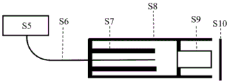
Fig. 5 is a schematic structural diagram of an endoscope provided in another exemplary embodiment of the present application. As shown in fig. 5, in the multiphoton endoscope structure based on liquid lens depth zoom, S5 is a femtosecond pulse laser and a fluorescence detection device, S6 is a double-clad optical fiber, S7 is a piezoelectric ceramic scanner, S9 is an objective lens assembly including a liquid lens, S10 is a biological sample tissue, and S8 is an endoscope probe structure integrating the piezoelectric ceramic scanner S7 and the objective lens assembly S9.
The femtosecond pulse laser S5 outputs near-infrared femtosecond pulse light, and the near-infrared femtosecond pulse light enters a fiber core of a double-clad fiber S6 for transmission, wherein the double-clad fiber S6 is used for transmitting excitation light and signal light, and the specific implementation form of the double-clad fiber can be a solid double-clad fiber or a hollow double-clad fiber (the hollow double-clad fiber comprises a double-clad photonic crystal band gap fiber, a double-clad antiresonance fiber and the like). The double-clad optical fiber S6 and the piezoelectric ceramic tube form a piezoelectric ceramic scanner S7, the double-clad optical fiber S6 is driven to scan by an external modulation signal, and the scanning mode can be spiral, Lissajous shape or grid shape. The excitation light is focused through an objective lens assembly S9 integrated with a liquid lens to biological sample tissue S10. The curvature of the liquid lens is adjusted through the applied voltage/external force, the up-and-down movement of the focus is realized, and therefore the three-dimensional depth scanning of the biological sample tissue S10 is realized. Due to the multi-photon excitation effect, a fluorescence signal and a second harmonic signal are generated at the biological sample tissue S10, and the signal light returns through the original optical path and is collected back to the fluorescence detection device S5 through the outer cladding of the double-clad optical fiber S6.
The embodiment of the application introduces the liquid lens into the multi-photon endoscope system, and the liquid lens zooms and compares the traditional mechanical zooming structure, so that the system not only has the advantages of high response speed, flexibility and high-speed zooming, simple control and the like, is more convenient for integrating the probe of the two-photon endoscope, and can meet the requirement of the two-photon endoscope on three-dimensional tissue imaging and assist in three-dimensional disease diagnosis.
For the stomach tissue, the structure is, in order from the inside to the outside, the mucosa, the submucosa, the muscularis and the serosa. Clinically, changes in the folds of the gastric mucosa often indicate that lesions may occur at the site, and gastric mucositis or mucosal cancer has spread in the submucosa. The liquid lens depth zoom-based multi-photon endoscope scans the stomach tissue to acquire information of different depths of the stomach tissue, is favorable for evaluating the development state of stomach diseases, and has important guiding significance for disease diagnosis and screening.
The foregoing describes the general principles of the present application in conjunction with specific embodiments, however, it is noted that the advantages, effects, etc. mentioned in the present application are merely examples and are not limiting, and they should not be considered essential to the various embodiments of the present application. Furthermore, the foregoing disclosure of specific details is for the purpose of illustration and description and is not intended to be limiting, since the foregoing disclosure is not intended to be exhaustive or to limit the disclosure to the precise details disclosed.
The block diagrams of devices, apparatuses, systems referred to in this application are only given as illustrative examples and are not intended to require or imply that the connections, arrangements, configurations, etc. must be made in the manner shown in the block diagrams. These devices, apparatuses, devices, systems may be connected, arranged, configured in any manner, as will be appreciated by those skilled in the art. Words such as "including," "comprising," "having," and the like are open-ended words that mean "including, but not limited to," and are used interchangeably therewith. The words "or" and "as used herein mean, and are used interchangeably with, the word" and/or, "unless the context clearly dictates otherwise. The word "such as" is used herein to mean, and is used interchangeably with, the phrase "such as but not limited to".
It should also be noted that in the devices, apparatuses, and methods of the present application, the components or steps may be decomposed and/or recombined. These decompositions and/or recombinations are to be considered as equivalents of the present application.
The previous description of the disclosed aspects is provided to enable any person skilled in the art to make or use the present application. Various modifications to these aspects will be readily apparent to those skilled in the art, and the generic principles defined herein may be applied to other aspects without departing from the scope of the application. Thus, the present application is not intended to be limited to the aspects shown herein but is to be accorded the widest scope consistent with the principles and novel features disclosed herein.
The foregoing description has been presented for purposes of illustration and description. Furthermore, the description is not intended to limit embodiments of the application to the form disclosed herein. While a number of example aspects and embodiments have been discussed above, those of skill in the art will recognize certain variations, modifications, alterations, additions and sub-combinations thereof.
Claims (10)
1. An endoscope, comprising:
the optical signal transmission assembly is used for transmitting an optical signal to the objective lens assembly;
the driver is used for driving the optical signal transmission assembly to scan;
and the objective lens assembly is used for adjusting the light signal to focus to different depth positions corresponding to the sample to be shot.
2. The endoscope of claim 1, wherein the objective lens assembly comprises a collimating and beam expanding module, a focusing module and a converging module, which are arranged in sequence, wherein the collimating and beam expanding module is configured to collimate and expand the optical signal emitted from the optical signal transmission assembly; the focusing module is used for adjusting the direction of the optical signal emitted by the collimation and beam expansion module; the convergence module is used for focusing the optical signals emitted by the focusing module to different depth positions corresponding to the sample to be shot.
3. The endoscope of claim 2, wherein the focusing module comprises a liquid lens, and the focusing module adjusts the direction of the optical signal emitted from the collimated beam expanding module according to the working state of the liquid lens, wherein the working state of the liquid lens comprises a concave lens state, a flat plate state, and a convex lens state.
4. The endoscope of claim 3, wherein the focusing module is further configured to: if the liquid lens is in the concave lens state, the focusing module emits a divergent light signal; if the liquid lens is in the flat plate state, the focusing module emits parallel light signals; and if the liquid lens is in the convex lens state, the focusing module emits a convergent optical signal.
5. The endoscope of claim 4, wherein the convergence module is further configured to: if the focusing module emits a divergent light signal, the convergence module focuses the divergent light signal to a first depth position corresponding to the sample to be shot; if the focusing module emits a parallel optical signal, the converging module focuses the parallel optical signal to a second depth position corresponding to the sample to be shot; and if the focusing module emits a converged light signal, the converged light signal is focused to a third depth position corresponding to the sample to be shot by the converging module.
6. The endoscope of claim 5, wherein a scan range of the endoscope is determined based on an imaging depth corresponding to the first depth position and an imaging depth corresponding to the third depth position.
7. An endoscope according to any of claims 3 to 6, and comprising a voltage control module connected to said liquid lens for adjusting the voltage applied to said liquid lens to adjust the operating state of said liquid lens.
8. The endoscope of any one of claims 3 to 6, wherein the endoscope comprises a pressure adjustment module connected to the liquid lens, the pressure adjustment module being configured to adjust a pressure applied to the liquid lens to adjust an operating state of the liquid lens.
9. The endoscope of any one of claims 2 to 6, wherein the focusing module is located between the collimated beam expanding module and the converging module.
10. The endoscope of any one of claims 1 to 6, wherein the collimated beam expanding module comprises any one or a combination of plano-convex, biconvex, plano-concave, and biconcave lenses.
Priority Applications (1)
| Application Number | Priority Date | Filing Date | Title |
|---|---|---|---|
| CN202111069703.6A CN113940605A (en) | 2021-09-13 | 2021-09-13 | Endoscope with a detachable handle |
Applications Claiming Priority (1)
| Application Number | Priority Date | Filing Date | Title |
|---|---|---|---|
| CN202111069703.6A CN113940605A (en) | 2021-09-13 | 2021-09-13 | Endoscope with a detachable handle |
Publications (1)
| Publication Number | Publication Date |
|---|---|
| CN113940605A true CN113940605A (en) | 2022-01-18 |
Family
ID=79328096
Family Applications (1)
| Application Number | Title | Priority Date | Filing Date |
|---|---|---|---|
| CN202111069703.6A Pending CN113940605A (en) | 2021-09-13 | 2021-09-13 | Endoscope with a detachable handle |
Country Status (1)
| Country | Link |
|---|---|
| CN (1) | CN113940605A (en) |
Cited By (1)
| Publication number | Priority date | Publication date | Assignee | Title |
|---|---|---|---|---|
| CN120315165A (en) * | 2025-06-11 | 2025-07-15 | 比亚迪股份有限公司 | Liquid lens focusing method, system, device, equipment, medium and product |
Citations (13)
| Publication number | Priority date | Publication date | Assignee | Title |
|---|---|---|---|---|
| KR20010007834A (en) * | 2000-10-05 | 2001-02-05 | 정규영 | Convex lens and concave lense convertable lens unit |
| US20090264707A1 (en) * | 2006-12-22 | 2009-10-22 | Koninklijke Philips Electronics N.V. | An imaging system with two imaging modalities |
| CN102436018A (en) * | 2006-12-15 | 2012-05-02 | 手持产品公司 | Apparatus and method comprising deformable lens element |
| US20120143004A1 (en) * | 2010-12-01 | 2012-06-07 | Adlens Beacon, Inc. | Variable Power Endoscope Based On Liquid Lens Technology |
| CN103048305A (en) * | 2012-12-07 | 2013-04-17 | 中国科学院西安光学精密机械研究所 | All-fiber laser Raman testing device |
| CN103054554A (en) * | 2012-12-29 | 2013-04-24 | 陈英俊 | Optical imaging device capable of deep scanning along axial direction and method and application thereof |
| CN105050475A (en) * | 2013-03-29 | 2015-11-11 | 索尼公司 | Laser scanning observation device and laser scanning method |
| CN108107505A (en) * | 2018-02-02 | 2018-06-01 | 北京超维景生物科技有限公司 | A kind of multi-photon endoscope structure of integrated double-cladding-layer photon band gap fiber |
| CN109381167A (en) * | 2018-12-18 | 2019-02-26 | 厦门大学 | Bimodal endoscope apparatus based on liquid lens self-focusing |
| CN109758098A (en) * | 2019-01-31 | 2019-05-17 | 北京超维景生物科技有限公司 | Zoom stype cavity endoscope detection device and laser scanning cavity endoscope |
| CN110881942A (en) * | 2019-12-11 | 2020-03-17 | 上海交通大学 | OCT-based bimodal optical fiber endoscope device |
| CN111227771A (en) * | 2020-01-09 | 2020-06-05 | 上海交通大学 | Self-focusing OCT endoscope with variable working distance |
| CN113267887A (en) * | 2021-05-19 | 2021-08-17 | 南京萃智激光应用技术研究院有限公司 | Flexible zoom lens and zooming method |
-
2021
- 2021-09-13 CN CN202111069703.6A patent/CN113940605A/en active Pending
Patent Citations (13)
| Publication number | Priority date | Publication date | Assignee | Title |
|---|---|---|---|---|
| KR20010007834A (en) * | 2000-10-05 | 2001-02-05 | 정규영 | Convex lens and concave lense convertable lens unit |
| CN102436018A (en) * | 2006-12-15 | 2012-05-02 | 手持产品公司 | Apparatus and method comprising deformable lens element |
| US20090264707A1 (en) * | 2006-12-22 | 2009-10-22 | Koninklijke Philips Electronics N.V. | An imaging system with two imaging modalities |
| US20120143004A1 (en) * | 2010-12-01 | 2012-06-07 | Adlens Beacon, Inc. | Variable Power Endoscope Based On Liquid Lens Technology |
| CN103048305A (en) * | 2012-12-07 | 2013-04-17 | 中国科学院西安光学精密机械研究所 | All-fiber laser Raman testing device |
| CN103054554A (en) * | 2012-12-29 | 2013-04-24 | 陈英俊 | Optical imaging device capable of deep scanning along axial direction and method and application thereof |
| CN105050475A (en) * | 2013-03-29 | 2015-11-11 | 索尼公司 | Laser scanning observation device and laser scanning method |
| CN108107505A (en) * | 2018-02-02 | 2018-06-01 | 北京超维景生物科技有限公司 | A kind of multi-photon endoscope structure of integrated double-cladding-layer photon band gap fiber |
| CN109381167A (en) * | 2018-12-18 | 2019-02-26 | 厦门大学 | Bimodal endoscope apparatus based on liquid lens self-focusing |
| CN109758098A (en) * | 2019-01-31 | 2019-05-17 | 北京超维景生物科技有限公司 | Zoom stype cavity endoscope detection device and laser scanning cavity endoscope |
| CN110881942A (en) * | 2019-12-11 | 2020-03-17 | 上海交通大学 | OCT-based bimodal optical fiber endoscope device |
| CN111227771A (en) * | 2020-01-09 | 2020-06-05 | 上海交通大学 | Self-focusing OCT endoscope with variable working distance |
| CN113267887A (en) * | 2021-05-19 | 2021-08-17 | 南京萃智激光应用技术研究院有限公司 | Flexible zoom lens and zooming method |
Cited By (2)
| Publication number | Priority date | Publication date | Assignee | Title |
|---|---|---|---|---|
| CN120315165A (en) * | 2025-06-11 | 2025-07-15 | 比亚迪股份有限公司 | Liquid lens focusing method, system, device, equipment, medium and product |
| CN120315165B (en) * | 2025-06-11 | 2025-10-17 | 比亚迪股份有限公司 | Liquid lens focusing method, system, device, equipment, medium and product |
Similar Documents
| Publication | Publication Date | Title |
|---|---|---|
| Zhao et al. | Development of a versatile two-photon endoscope for biological imaging | |
| JP5599818B2 (en) | Optical probe | |
| US7969659B2 (en) | Grin lens microscope system | |
| JP7175123B2 (en) | Variable focal length lens device | |
| JP2007503938A (en) | Integrated optical scanning image acquisition and display | |
| CN1795405A (en) | Double Clad Fiber Scanning Microscope | |
| EP3097443A1 (en) | Optical imaging devices and variable-focus lens elements, and methods for using them | |
| CN113900247B (en) | Endoscope | |
| CN105954862A (en) | Microscopic lens and sample locking system based on 4Pi microscope framework | |
| KR20230107782A (en) | Image calibration algorithm based on lissajous scanning | |
| JP2021519451A (en) | Improved scanning light microscopy | |
| Seibel et al. | Microfabricated optical fiber with a microlens that produces large field-of-view video-rate optical beam scanning for microendoscopy applications | |
| CN110537898B (en) | Manufacturing method of focus-adjustable photoacoustic endoscopic microscope | |
| CN113940605A (en) | Endoscope with a detachable handle | |
| US9717416B2 (en) | Optical zoom probe | |
| CN107966424B (en) | Side imaging method and device based on anti-telescope system and free-form surface reflection | |
| JP2000126115A (en) | Optical scanning probe device | |
| CN116953905A (en) | Oblique light piece imaging system | |
| CN113710142B (en) | Ultra-compact folded beam path confocal endoscopic microscope | |
| JP4240754B2 (en) | Telecentric optics | |
| Moallemi et al. | Development of a hybrid piezoelectric and pneumatic miniature optical scanner for endoscopic applications | |
| CN116519594A (en) | A cross-scale photoacoustic imaging system | |
| CN116509327B (en) | Multiscale photoacoustic imaging method based on liquid lenses | |
| JP2004065965A (en) | Optical scanning probe | |
| JP2002301018A (en) | Optical scanning probe device |
Legal Events
| Date | Code | Title | Description |
|---|---|---|---|
| PB01 | Publication | ||
| PB01 | Publication | ||
| SE01 | Entry into force of request for substantive examination | ||
| SE01 | Entry into force of request for substantive examination |